EP0282966A2 - Méthode et dispositif pour la fabrication des images en trois dimensions - Google Patents
Méthode et dispositif pour la fabrication des images en trois dimensions Download PDFInfo
- Publication number
- EP0282966A2 EP0282966A2 EP88104074A EP88104074A EP0282966A2 EP 0282966 A2 EP0282966 A2 EP 0282966A2 EP 88104074 A EP88104074 A EP 88104074A EP 88104074 A EP88104074 A EP 88104074A EP 0282966 A2 EP0282966 A2 EP 0282966A2
- Authority
- EP
- European Patent Office
- Prior art keywords
- images
- sensor
- display
- platform
- ized
- Prior art date
- Legal status (The legal status is an assumption and is not a legal conclusion. Google has not performed a legal analysis and makes no representation as to the accuracy of the status listed.)
- Withdrawn
Links
Images


Classifications
-
- G—PHYSICS
- G03—PHOTOGRAPHY; CINEMATOGRAPHY; ANALOGOUS TECHNIQUES USING WAVES OTHER THAN OPTICAL WAVES; ELECTROGRAPHY; HOLOGRAPHY
- G03B—APPARATUS OR ARRANGEMENTS FOR TAKING PHOTOGRAPHS OR FOR PROJECTING OR VIEWING THEM; APPARATUS OR ARRANGEMENTS EMPLOYING ANALOGOUS TECHNIQUES USING WAVES OTHER THAN OPTICAL WAVES; ACCESSORIES THEREFOR
- G03B35/00—Stereoscopic photography
- G03B35/18—Stereoscopic photography by simultaneous viewing
- G03B35/26—Stereoscopic photography by simultaneous viewing using polarised or coloured light separating different viewpoint images
-
- G—PHYSICS
- G03—PHOTOGRAPHY; CINEMATOGRAPHY; ANALOGOUS TECHNIQUES USING WAVES OTHER THAN OPTICAL WAVES; ELECTROGRAPHY; HOLOGRAPHY
- G03B—APPARATUS OR ARRANGEMENTS FOR TAKING PHOTOGRAPHS OR FOR PROJECTING OR VIEWING THEM; APPARATUS OR ARRANGEMENTS EMPLOYING ANALOGOUS TECHNIQUES USING WAVES OTHER THAN OPTICAL WAVES; ACCESSORIES THEREFOR
- G03B35/00—Stereoscopic photography
- G03B35/16—Stereoscopic photography by sequential viewing
-
- H—ELECTRICITY
- H04—ELECTRIC COMMUNICATION TECHNIQUE
- H04N—PICTORIAL COMMUNICATION, e.g. TELEVISION
- H04N13/00—Stereoscopic video systems; Multi-view video systems; Details thereof
- H04N13/10—Processing, recording or transmission of stereoscopic or multi-view image signals
- H04N13/189—Recording image signals; Reproducing recorded image signals
-
- H—ELECTRICITY
- H04—ELECTRIC COMMUNICATION TECHNIQUE
- H04N—PICTORIAL COMMUNICATION, e.g. TELEVISION
- H04N13/00—Stereoscopic video systems; Multi-view video systems; Details thereof
- H04N13/20—Image signal generators
- H04N13/204—Image signal generators using stereoscopic image cameras
- H04N13/207—Image signal generators using stereoscopic image cameras using a single two-dimensional [2D] image sensor
- H04N13/211—Image signal generators using stereoscopic image cameras using a single two-dimensional [2D] image sensor using temporal multiplexing
-
- H—ELECTRICITY
- H04—ELECTRIC COMMUNICATION TECHNIQUE
- H04N—PICTORIAL COMMUNICATION, e.g. TELEVISION
- H04N13/00—Stereoscopic video systems; Multi-view video systems; Details thereof
- H04N13/20—Image signal generators
- H04N13/204—Image signal generators using stereoscopic image cameras
- H04N13/207—Image signal generators using stereoscopic image cameras using a single two-dimensional [2D] image sensor
- H04N13/221—Image signal generators using stereoscopic image cameras using a single two-dimensional [2D] image sensor using the relative movement between cameras and objects
-
- H—ELECTRICITY
- H04—ELECTRIC COMMUNICATION TECHNIQUE
- H04N—PICTORIAL COMMUNICATION, e.g. TELEVISION
- H04N13/00—Stereoscopic video systems; Multi-view video systems; Details thereof
- H04N13/10—Processing, recording or transmission of stereoscopic or multi-view image signals
-
- H—ELECTRICITY
- H04—ELECTRIC COMMUNICATION TECHNIQUE
- H04N—PICTORIAL COMMUNICATION, e.g. TELEVISION
- H04N13/00—Stereoscopic video systems; Multi-view video systems; Details thereof
- H04N13/10—Processing, recording or transmission of stereoscopic or multi-view image signals
- H04N13/106—Processing image signals
- H04N13/161—Encoding, multiplexing or demultiplexing different image signal components
-
- H—ELECTRICITY
- H04—ELECTRIC COMMUNICATION TECHNIQUE
- H04N—PICTORIAL COMMUNICATION, e.g. TELEVISION
- H04N19/00—Methods or arrangements for coding, decoding, compressing or decompressing digital video signals
- H04N19/50—Methods or arrangements for coding, decoding, compressing or decompressing digital video signals using predictive coding
- H04N19/597—Methods or arrangements for coding, decoding, compressing or decompressing digital video signals using predictive coding specially adapted for multi-view video sequence encoding
Definitions
- the present invention relates to a method of three-dimensional imaging according to the preamble of claim 1 and to an apparatus for implementing said method.
- the related art incorporates both two-dimensional and three-dimensional imaging with single and double sensors, respectively.
- Some related art may consist of a system with one sensor or camera which is time-shared between binocular-type optics using a mechanized mirror assembly allegedly producing a three-dimensional characteristic caused by a horizontal parallax limited to the distance between left and right optics in front of the camera lens.
- the disadvantages of such system are that it has an undesirable horizontally "jogging" image of dynamic scenes and a severely limited stereo base.
- the double sensor system relies on horizontal parallax for three dimensional imaging.
- the only known related art which utilizes single sensor three dimensional imaging for binocular display is a situation where several photographs are taken of objects moving along side a platform holding the sensor. The several photographs are taken at different points in time and then are presented with a three dimensional effect to the viewer through horizontal parallax.
- this type of three dimensional system is non-effectual for objects moving toward the platform.
- the object of the present invention to provide a method for three-dimensional imaging of objects with a single sensor where the objects are moving towards or away from the sensor.
- the present invention requires only one sensor for three-dimensional imaging.
- the invention has a sensing means, processing means and three-dimensional display means.
- the processing means has converting means for converting image analog signals to digital signals which are sent on to buffer means. These images are appropriately selected by multiplexing means from buffer means for effecting three-dimensional images to the display means for viewing in color or monochrome. The images viewed may be in near real-time or of delayed recordings.
- the buffer means and multiplexing means receive signals from microprocessor means which does modeling from parameters, such as altitude, velocity and its vector, of the platform upon which the sensing means is mounted.
- the image signals to the display means may be combined or conditioned by signal conditioning means.
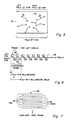
- Fig. 1 assume sensor 12 at point A translating horizontally with respect to the image world 14, or vice versa, and denote its relative progression in the terms of time ( ⁇ t), then the average relative velocity of sensor 12 will determine sensor positions and, therefore, the separation, or stereo base, inherent to a pair of images captured at times A and B.
- This is the standard aerial method of stereo photo reconnaissance in which a single sensor platform flies in a straight line, constant altitude, and fixed velocity course, taking pictures at regular intervals (i.e., ⁇ t) and producing definite stereo left (L) and right (R) images. The situation is different if the relative motions of sensor 12 and the world 14 are altered as shown in Figure 2.
- the sensor 12 flies "into" the object field 14 which it is imaging, creating radial expansions of the objects 14 about the sensor's axis 16 of motion.
- the advantage of the present invention is that it transforms the effects of radial expansion disparities into a good stereo image.
- a further advantage of the invention is that it processes the images of radial expansion into a "live" moving image, very useful for dynamic situations.
- Still another advantage of the present invention is that an observer perceiving the three dimensional image shall continue to perceive a three dimensional image upon a lateral tilt of the observer's head or the rotation of the display due to the resultant features of processing of images with radial parallax.
- the invention also has capability of providing "strong" stereo visual effect for very distant objects as well as near objects.
- Figure 3 shows imaging sensor 12 in relationship to platform 20 which moves along axis 16.
- Sensor 12 has a set of optics 24, focal plane 22, and associated sensor electronics 23 for receiving the image of objects 14 along optical axis 18.
- Figure 4 shows a top view of the sensor 12 and platform 20.
- the optical axis 18 may not necessarily be parallel with the direction of the platform axis 16.
- optical axis 18 is assumed to be in a plane parallel to the plane that the direction of motion axis 16 is in.
- the direction of optical axis 18 relative to the direction of motion axis 16 can be measured as angle C.
- Platform 20 may contain image processing electronics 26 and display 28.
- Figure 5 shows an image of display 28 when angle C is equal to 0 degrees, that is, axes 16 and 18 are parallel to each other.
- the field of view of display 28 is split into a left field of view 32 and right field of view 34 by inertial field midline 30.
- Inertial field midline 30 is a line which coincides with direction of motion axis 16 and reveals the direction of movement of platform 20.
- Midline 30 is perpendicular to the horizontal plane of platform 20.
- Display 28 shows a video image of objects 14.
- the arrows adjacent to each of objects 14 reveal the direction of the motion of each object 14 on display 20 over a period of time as platform 20 moves along axis 16.
- Objects 14 flow away from optic axis 18 at the middle of display 28 while platform 20 moves in a direction forward along motion axis 16 which coincides with optical axis 18 in Figure 5.
- Figure 6 is an illustration of the sequence of display information presented to the left eye and to the right eye of an observer. The timing of this information has its base in 60 Hertz per second.
- Blocks 38 and 42 of video information are presented to display 28 in a sequential order during a period of time represented by time axis 36.
- Blocks 38 represent fields of information presented on display 28 for the left eye only.
- Blocks 42 of fields of information are presented on display 28 for the right eye only.
- Block 38 labeled 1 o represents a field of odd video scan lines 44 for frame 48 in Figure 7.
- Block 38 labeled 1 e represents even field scan lines 46 for frame 48.
- the first two blocks 38 represent the first frame for the left eye as presented on display 28 in the form of video frame 48.
- Video frame 48 is composed of interlaced fields of odd lines 44 and even lines 46.
- Blocks 42 labeled 1 o and 1 e represent the two fields of odd lines 44 and even lines 46 which are interlaced to form video frame 48 on display 28 for the right eye.
- the first two blocks 42 compose the first frame for the right eye.
- the first two blocks 38 and the first two blocks 42 as described above compose a stereoscopic frame.
- the delay between the image presented to the left eye and the image presented to the right eye is the amount of time that block 38 labeled 1 o takes to be presented in a video frame 48 on display 28.
- the odd field for the right eye is started and presented in video frame 48 on display 28.
- the delay is 8.33 milliseconds.
- the time that the field as represented by block 42 labeled 1 o may be presented at a time greater than 8.33 millisecond delay from the start of block 38 labeled 1 o , or that delay may be less than 8.33 milliseconds limited only by the sensor field duration.
- the delay may be the duration of presenting a complete frame to one eye up to the time a new frame is presented to the other eye.
- the design described in the preceding and present paragraphs is for a Stereographics Corporation, San Rafael, CA 94912, field sequential display in which the CRT screen display 28 is "time shared" by the left and right eyes.
- the display has an LCD cover that functions as a light valve which alternates with different polarization on the light emitted from the screen or display 28.
- One polarization is clockwise and the other polarization is counter clockwise and they are alternated so that the left eye sees information on display 28 which the other eye does not and vice versa according to the polarization mode of the displayed information on the screen.
- the observer wears a passive set of glasses which permits one eye to see the image on the display which has the same polarization as the eye piece over the respective eye and permits the other eye to see an image of another polarization due to the other eye piece having the latter polarization. Since these polarizations are circular and the parallax is radial, the observer can still perceive three dimensional images even when his head is in a tilted position.
- Figure 8 shows a frame for left eye 62 and a frame for right eye 64 respectively on display 28. Similar to Figure 5, the field of view as represented by the two frames is divided by inertial field midline 30.
- the frame to left eye 62 has a left field of view 52 and right field of view 54
- the frame to right eye 64 has a left field of view 56 and a right field of view 58.
- the frame to left eye 62 may be composed of fields 1 and 2 and the frame for right eye 64 may be composed of fields 3 and 4.
- the frame to right eye 64 is delayed in time relative to the frame to left eye 62. The delay of the frame to right eye 64 may be increased by using later fields such as 5 and 6, or 7 and 8, etc.
- the frames in Figure 8 may each be cut into subframes corresponding to the left and right fields of view, respectively, on inertial field midline 30. Then the respective subframes 52, 54, 56 and 58 may be recombined in a manner as shown in Figure 9, that is, subframes 52 and 58 are combined to be presented to left eye 62 and subframes 56 and 54 are combined to be presented to right eye 64. This recombination is necessary to eliminate any pseudo-stereo sometimes present in the image.
- Figure 10 and 11 explain why the frames are cut along midline 30 and recombined as illustrated in Figure 9.
- Figure 10 shows a partially desired three dimensional effect of objects to the viewer as presented with frames in the format as shown in Figure 8, that is, with subframes 52 and 54 presented to left eye 62 and subframes 56 and 58 to right eye 64.
- the observer looking at display 28 sees frames 1 and 2 overlapping each other in Figure 10.
- Display 28 shows a moving object 1 in the left fields of view having subframes 52 and 56 for left and right eyes 62 and 64, respectively, and a moving object 2 in the right fields of view having subframes 54 and 58 for the left and right eyes 62 and 64, respectively.
- object 1 is represented by spot 70 which is displayed on subframe 52 and visible only to left eye 62 along optical axis 66.
- object 1 is represented by spot 72 on subframe 56 which is seen only by right eye 64 along optical axis 68.
- Optical axis 66 of left eye 62 and optical axis 68 of right eye 64 intersect at point 74.
- Object 1 appears at the intersection of optical axes 66 and 68 closer to the observer than the surface of display 28.
- the surface of display 28 is depicted as being perpendicular to the surface of Figure 10 itself.
- the three dimensional effect is different for the right field of view as portrayed by subframes 54 and 58.
- Object 2 is represented at t1 equal to 0 by spot 80 on the screen as displayed by subframe 54 which is visible to only the left eye 62 along optical axes 76.
- object 2 is represented by spot 82 on the screen by subframe 58 which is seen only by right eye 64 along optical axis 78.
- the radial parallax due to motion of platform 20 towards the objects 14 is responsible for the representation of object 2 moving from spot 80 to spot 82 during the duration of 8 milliseconds, similar to the movement of the representation of object 1 from spot 70 to spot 72 in the left field of view.
- left eye 62 sees object 2 along optical axis 76 at spot 80 and right eye 64 sees object 2 at spot 82 along optical axis 78 appearing to be displayed on the screen at approximately the same time.
- the intersection of optical axis 76 of left eye 62 and optical axis 78 of right eye 64 intersect at point 84 where object 2 appears to the observer; that is, object 2 at point 84 has the appearance at being a further distance from the observer than the surface of the screen of display 28.
- spots 70 and 72 move further apart from each other and intersection 74 comes closer to the observer thus giving the observer a perception of object 1 approaching him.
- spots 80 and 82 move further apart resulting in the intersection 84 of optical axes 76 and 78 moving further into the back of the screen surface and causing object 2 to appear at a greater distance as time goes on, or giving the observer a perception of object 2 receding from the observer in terms of binocular disparity (although object 2 grows in size on the display as it would in approaching the sensor).
- Subframes 52 and 58 are put together so that the earliest events which left eye 62 sees consist of right-most displaced points.
- Right eye 64 sees subframes 56 and 54 showing the left-most displaced points as representing the earliest events. This subframe combination is illustrated by Figure 9 as noted above.
- Figure 12 illustrates full stereo vision of objects 1 and 2 for both the left and right fields of view.
- Figure 12 is similar to the diagram in Figure 10 except for the right field of view.
- subframe 52 is shown to left eye 62 displaying spot 70 at t1 equal to 0 time
- subframe 58 is presented to left eye 62 showing spot 82 at time t2 equal to 8 milliseconds.
- Right eye 64 sees another set of subframes 54 and 56 which are not seen by left eye 62.
- Subframe 54 presents to right eye 64 spot 80 at t1 equal to 0 time reference.
- Subframe 56 presents to right eye 64 spot 72 at t2 equal to 8 milliseconds.
- left eye 62 sees spot 70 along axis 66 and right eye 64 sees spot 72 along axis 68.
- Axes 66 and 68 intersect at point 74 presenting a perception of object 1 in stereoscopic vision represented to the observer as being closer to the observer than the surface of the screen or display 28.
- left eye 62 sees along axis 76 spot 82 at t2 equal to 8 milliseconds.
- Right eye 64 sees spot 80 at t1 equal to 0 time along axis 78.
- the axes 76 and 78 intersect at point 85 thus presenting a stereoscopic presentation of object 2 to the observer.
- the observer perceives object 2 to be closer to him than the surface of the screen or display 28. This results in a true stereoscopic display from a single sensor for the full field of view.
- the invention preserves the three dimensional characteristic of the images presented to the observer on display 28.
- Optical axis 18 of sensor 12 and direction of motion 16 of platform 20 in Figure 4 need not be coincident; in other words, angle C need not be 0 degrees.
- the inertial field midline 30 of Figure 5, which indicates the direction of motion 16 of platform 20, defines the split between the left field of view 32 and the right field of view 34 which consist of subframes 52 and 56, and 58 and 54, respectively.
- the inertial field midline 30 discriminates between the right and left flows of observed objects 14.
- Figure 13 shows display 28 as sensor 12 is "panned" to the left.
- Inertial field midline 30 always reveals the direction of the platform 20 on which sensor 12 is mounted.
- left field of view 32 increases in size and right field of view 34 decreases in size.
- subframes 52 and 56 increase in size and subframes 58 and 54 decrease in size.
- Angle C between optical axis 18 and inertial field midline 30 increases.
- Inertial field midline 30 on display 28 splitting left field of view 32, consisting of subframes 52 and 56, from right field of view 34, consisting of subframes 58 and 54, is effected through frame buffering, frame cutting and frame recombination like that as noted in Figure 9 above.
- the frame cuts are made along the inertial field midline 30 as defined by direction of motion 16 of platform 20.
- the position of the inertial field midline 30 may shift left or right across the field of view as sensor 12 pans right or left, respectfully.
- Sensor 12 may be rotated 360° relative to platform 20.
- Figure 14 shows the display to left eye 62 and display to right eye 64, respectively, as sensor 12 is rotated to the right.
- the inertial field midline 30 in both displays slews to the left in the sensor 12 field of view resulting in a decrease in size of the left field of view 32 in the presentations to the left eye 62 and right eye 64 respectfully, and an increase in right field of view 34 in the presentations to the left eye 62 and right eye 64, respectively. If sensor 12 continues to rotate, at some point, the inertial field midline 30 will move so far to one side as to not be coincident with any portion of the display as shown in Figure 15.
- sensor 12 is rotated to the left and inertial field midline 30 slews to the right until it leaves sensor 12 field of view, thus allowing the observer to see only left field of view 32 presenting subframe 52 to left eye 62 and subframe 56 to right eye 64, respectively. Whether the sensor rotates far to right or to the left the flow of objects 14 provides an appropriate delay for a side-looking single sensor three dimensional presentation of the objects.
- Sensor 12 may be rotated so that its field of view spans an inertial field midline 31 as sensor 12 looks to the rear of platform 20 as depicted in Figures 17a and 17b. Sensor 12 in this position results in angle C being equal to 180° between optical axis 18 and direction of movement 16.
- sensor 12 sees receding objects having a flow moving inward resulting in a radial parallax.
- Subframe 58 and subframe 52, divided by inertial field midline 31 are presented to left eye 62
- subframe 54 and subframe 56 divided by inertial field midline 31, are presented to right eye 64. The observer continues to see the three dimensional effect of objects 14.
- Subframes 58 and 52, and 54 and 56, respectively, are combined through frame buffering, cutting and recombining as well known in the field of digital video electronic arts.
- frame buffering cutting and recombining as well known in the field of digital video electronic arts.
- Figures 18, 19 and 20 show block diagrams of an embodiment 90, including a color video version 130, of the present invention. All connecting lines in Figures 18, 19 and 20, can carry either parallel or serial signals.
- sensor 12 may be a charged coupled device (CCD) video camera, an infrared imaging sensor, or other image sensing device.
- CCD charged coupled device
- sensor 12 is a video CCD camera which sends a 30 Hz frame to analog-to-digital converter 92.
- Analog-to-digital converter 92 sends a digital image stream to frame buffers 94.
- frame buffers 94 split the frames into subframes, according to left and right field of view 32 and 34, and recombine them, as described above.
- Inertial field reference 30 or 31 which splits the sensor 12 field of view, is determined by microprocessor 98 for modeling together with other parameters such as velocity and altitude of the platform 20, sent as signals from platform parameters 96.
- Processed signals are sent by microprocessor 98 to frame buffers 94 for implementing inertial field midline 30 or 31 for each frame.
- microprocessor 98 sends a buffer select signal to multiplexers 102 which select frames having particular time delays for effecting stereo display of sensed objects 14. Selected frames by multiplexers 102 are sent to interface 104 for combining, signal conditioning, or just for passing on the signal as sent out from the multiplexers 102 on to three dimensional display 28.
- Microprocessor model 28 also sends a signal generator lock signal to sensor 12 for purposes of synchronization.
- Figure 19 shows greater detail of electronics which effect the stereoscopic display of data from sensor 12 of embodiment 90 of the present invention.
- Figure 19 overall shows in essence a processing section 126 of embodiment 90 in conjunction with inputs 124 and outputs 128.
- Analog-to-digital converter 92 is an eight-bit converter which receives analog video signals from sensor 12 and converts them into a stream of digital signals which are fed onto frame buffers 94.
- Frame buffers 94 consist of a series of RS-170 buffer memories 106, 108, 110, 112, 114 and 116. Buffer memories are each designed to hold a monoscopic frame, each frame having a 33 millisecond delay from the other.
- buffer memory 106 may hold the first frame (having buffer 106 arbitrarily labeled as frame number 1) for indicating the order of a certain series of frames being fed to the buffer memories according to time.
- Buffers 108, 110, 112 and 114 each are designed to hold the second, third, fourth and fifth frames, respectively, of the video information.
- These buffers have adjustable windows which allow for frame cutting and recombination in accordance with the location of inertial field midline 30 or 31 relative to the direction of optical axis 18 as depicted above.
- Microprocessor model 98 takes inertial reference, platform velocity and altitude information to provide an X signal down line 119 for purposes of a model selection of buffer windows to optimize the ⁇ t between the selected frames for effecting the three dimensional effect on displays 28, 121 and 122.
- the X signal on line 119 is an averaged X of two buffers selected for a stereo frame. This signal is derived mainly from the inertial reference, i.e., motion axis 16, which is translated to an X axis number (i.e., pixel column number) of a buffer column (X).
- a model based on aforementioned parameters and calculated by microprocessor 98 determines sizes of buffer windows of buffers 106, 108, 110, 112 and 114. Two of these buffers are selected by left eye video multiplexer 118 and right eye video multiplexer 120 as determined by buffer select line to multiplexers 118 and 120 from microprocessor 98.
- the buffer selection optimizes ⁇ t, i.e., duration of time between selected frames, which is specific for a particular mission of platform 20.
- Microprocessor 98 is dedicated to these determinations.
- Buffer 106 may be selected at any given time as the earliest frame to be viewed and one other buffer determined by the amount of delay desired for stereoscopic effect is selected.
- the time difference from one buffer to another is 33 milliseconds multiplied by the number of buffers down-stream from buffer 106.
- One or more additional RS-170 buffer memories 116 may be added for additional delay.
- the total number of buffers incorporated in frame buffers 94 depends on the maximum amount of delay desired or required between the earliest and latest frame for stereoscopic display purposes.
- the outputs of left and right video multiplexers 118 and 120 which are left eye display and right eye display signals, respectively, may be fed directly to binocular helmet mounted display 121. Also, the signals from the left and right video multiplexers 118 and 120 may be combined by video combiner 104 into a signal to be fed down one line as alternating left/right display signals to field-sequential binocular display 28.
- Recorder 103 is connected to multiplexers 102. Recorder 103 is for delayed recordings of images for replaying and viewing at a substantially later time than the time of recording. Video combiner 104 may condition the display signals from multiplexer 118 and 120 into a form for reception on other kinds of displays such as display 122.
- Figure 20 shows embodiment 90 as illustrated in Figures 18 and 19 expanded for a single sensor three dimensional color video display system 130.
- the color video embodiment 130 is in essence a triplicate of much of the electronics described in Figures 18 and 19.
- Color video sensor 13 is mounted similarly as video sensor 12 on platform 20.
- Platform parameters device 96 and microprocessor model 98 are each single in number and the same as those in embodiment 90.
- Color video sensor 13 sends out three signals each of which is a video analog intensity signal like that from sensor 12, except that each of the three signals from color video sensor 13 is grounded in a primary color, i.e., red, green and blue, respectively.
- the red, green and blue video analog signals are converted by analog-to-digital converters 132, 142 and 152, respectively.
- These analog-to-digital converters send out digital image streams to frame buffers 134, 144 and 154, respectively, which have identical window adjustments for purposes of cutting frames into subframes and recombining the subframes into displays having inertial field midline 30 as determined by X sent down line 119 to the frame buffers 134, 144 and 154.
- the outputs of frame buffers 134, 144 and 154 are sent to multiplexers 136, 146 and 156, corresponding to red, green and blue signals, respectively.
- Buffer-select signals from microprocessor 98 are sent to multiplexers 136, 146 and 156, to select the respective frames for combining and transmission as right and left display signals based in the three primary colors including red, green and blue.
- the outputs of multiplexers 136, 146 and 156 are sent to interfaces 138, 148 and 158 for video combining or other signal conditioning for display purposes.
- the resultant display signals for red, green and blue components, from interfaces 138, 148 and 158, respectively, are sent to video display 160 so that an observer may view, in three dimensional color, an image picked up by single sensor 13.
Landscapes
- Engineering & Computer Science (AREA)
- Multimedia (AREA)
- Signal Processing (AREA)
- Physics & Mathematics (AREA)
- General Physics & Mathematics (AREA)
- Testing, Inspecting, Measuring Of Stereoscopic Televisions And Televisions (AREA)
- Stereoscopic And Panoramic Photography (AREA)
- Radar Systems Or Details Thereof (AREA)
Applications Claiming Priority (2)
| Application Number | Priority Date | Filing Date | Title |
|---|---|---|---|
| US07/028,359 US4754327A (en) | 1987-03-20 | 1987-03-20 | Single sensor three dimensional imaging |
| US28359 | 1987-03-20 |
Publications (2)
| Publication Number | Publication Date |
|---|---|
| EP0282966A2 true EP0282966A2 (fr) | 1988-09-21 |
| EP0282966A3 EP0282966A3 (fr) | 1990-01-31 |
Family
ID=21843018
Family Applications (1)
| Application Number | Title | Priority Date | Filing Date |
|---|---|---|---|
| EP88104074A Withdrawn EP0282966A3 (fr) | 1987-03-20 | 1988-03-15 | Méthode et dispositif pour la fabrication des images en trois dimensions |
Country Status (4)
| Country | Link |
|---|---|
| US (1) | US4754327A (fr) |
| EP (1) | EP0282966A3 (fr) |
| JP (1) | JPS647793A (fr) |
| IL (1) | IL85359A (fr) |
Cited By (4)
| Publication number | Priority date | Publication date | Assignee | Title |
|---|---|---|---|---|
| EP0377480A3 (fr) * | 1989-01-06 | 1991-10-02 | Teleatlas International B.V. | Procédure pour établir et tenir à jour des fichiers pour trafic routier |
| GB2312122A (en) * | 1996-03-08 | 1997-10-15 | Ibm | Graphics display system |
| DE19617643A1 (de) * | 1996-05-02 | 1997-11-13 | Siemens Nixdorf Inf Syst | Verfahren zum Konvertieren von 2D- in 3D-Filme |
| WO1999057597A3 (fr) * | 1998-05-05 | 1999-12-23 | Richard Schubert | Dispositif pour realiser des prises de vue tridimensionnelles d'objets au moyen de scanners optiques, et procede d'acquisition d'objets en trois dimensions |
Families Citing this family (36)
| Publication number | Priority date | Publication date | Assignee | Title |
|---|---|---|---|---|
| US4875034A (en) * | 1988-02-08 | 1989-10-17 | Brokenshire Daniel A | Stereoscopic graphics display system with multiple windows for displaying multiple images |
| US4956705A (en) * | 1989-03-10 | 1990-09-11 | Dimensional Visions Group | Electronic method and apparatus for stereoscopic photography |
| FR2650465B1 (fr) * | 1989-07-26 | 1996-06-21 | France Etat | Procede de traitement et de transmission par un canal de type " mac " d'une sequence de couple d'images de television stereoscopique |
| US5577130A (en) * | 1991-08-05 | 1996-11-19 | Philips Electronics North America | Method and apparatus for determining the distance between an image and an object |
| US5715383A (en) * | 1992-09-28 | 1998-02-03 | Eastman Kodak Company | Compound depth image display system |
| WO1995013564A1 (fr) * | 1993-11-09 | 1995-05-18 | Eric Martin White | Procede et appareil de visualisation en trois dimensions d'images cinematographiques bidimensionnelles |
| US5543964A (en) * | 1993-12-28 | 1996-08-06 | Eastman Kodak Company | Depth image apparatus and method with angularly changing display information |
| ES2078176B1 (es) * | 1993-12-31 | 1998-01-16 | Lobo Gomez Arturo | Procedimiento de visualizacion de imagenes tridimensionales y sus correspondientes dispositivos. |
| US5523886A (en) * | 1994-01-04 | 1996-06-04 | Sega Of America, Inc. | Stereoscopic/monoscopic video display system |
| CN1113320C (zh) * | 1994-02-01 | 2003-07-02 | 三洋电机株式会社 | 将二维图像转换成三维图像的方法以及三维图像显示系统 |
| JP2846840B2 (ja) * | 1994-07-14 | 1999-01-13 | 三洋電機株式会社 | 2次元映像から3次元映像を生成する方法 |
| JP2846830B2 (ja) * | 1994-11-22 | 1999-01-13 | 三洋電機株式会社 | 2次元映像を3次元映像に変換する方法 |
| US5615046A (en) * | 1995-01-23 | 1997-03-25 | Cyber Scientific Inc. | Stereoscopic viewing system |
| KR100414629B1 (ko) * | 1995-03-29 | 2004-05-03 | 산요덴키가부시키가이샤 | 3차원표시화상생성방법,깊이정보를이용한화상처리방법,깊이정보생성방법 |
| US5835133A (en) * | 1996-01-23 | 1998-11-10 | Silicon Graphics, Inc. | Optical system for single camera stereo video |
| US5883695A (en) * | 1997-09-19 | 1999-03-16 | Paul; Eddie | Method and apparatus for producing stereoscopic images with single sensor |
| US6094215A (en) * | 1998-01-06 | 2000-07-25 | Intel Corporation | Method of determining relative camera orientation position to create 3-D visual images |
| US6304284B1 (en) * | 1998-03-31 | 2001-10-16 | Intel Corporation | Method of and apparatus for creating panoramic or surround images using a motion sensor equipped camera |
| US6282650B1 (en) | 1999-01-25 | 2001-08-28 | Intel Corporation | Secure public digital watermark |
| JP4685313B2 (ja) * | 1999-12-29 | 2011-05-18 | ジオスパン コーポレイション | 任意の局面の受動的な体積画像の処理方法 |
| JP3983953B2 (ja) * | 2000-03-10 | 2007-09-26 | パイオニア株式会社 | 立体的2次元画像表示装置及び画像表示方法 |
| KR100815897B1 (ko) * | 2001-10-13 | 2008-03-21 | 엘지.필립스 엘시디 주식회사 | 액정표시장치의 데이터 구동 장치 및 방법 |
| US8483960B2 (en) | 2002-09-20 | 2013-07-09 | Visual Intelligence, LP | Self-calibrated, remote imaging and data processing system |
| US8994822B2 (en) | 2002-08-28 | 2015-03-31 | Visual Intelligence Lp | Infrastructure mapping system and method |
| US7893957B2 (en) * | 2002-08-28 | 2011-02-22 | Visual Intelligence, LP | Retinal array compound camera system |
| US7466336B2 (en) * | 2002-09-05 | 2008-12-16 | Eastman Kodak Company | Camera and method for composing multi-perspective images |
| USRE49105E1 (en) | 2002-09-20 | 2022-06-14 | Vi Technologies, Llc | Self-calibrated, remote imaging and data processing system |
| KR100448882B1 (ko) * | 2002-11-14 | 2004-09-18 | 한국전자통신연구원 | 양안식 멀티미디어 컨텐츠 저작 장치 및 그 방법 |
| JP2004241798A (ja) * | 2003-02-03 | 2004-08-26 | Sharp Corp | 立体映像記録再生装置 |
| US20060012753A1 (en) * | 2004-07-13 | 2006-01-19 | Gandara Robert A | Stereoscopic imaging |
| KR100580218B1 (ko) * | 2004-12-30 | 2006-05-16 | 삼성전자주식회사 | 하나의 프로젝터를 사용한 투사형 3차원 영상 디스플레이장치 |
| EP2078229A2 (fr) * | 2006-11-02 | 2009-07-15 | Sensics, Inc. | Systèmes et procédés pour affichage monté sur la tête |
| US9191649B2 (en) | 2011-08-12 | 2015-11-17 | Qualcomm Incorporated | Systems and methods to capture a stereoscopic image pair |
| CN102645836A (zh) * | 2012-04-20 | 2012-08-22 | 中兴通讯股份有限公司 | 一种照片拍摄方法及电子设备 |
| ES2865491T3 (es) | 2015-06-26 | 2021-10-15 | Sz Dji Technology Co Ltd | Sistema y método para seleccionar un modo de operación de una plataforma móvil |
| EP3392707A4 (fr) * | 2015-12-14 | 2019-08-07 | Olympus Corporation | Dispositif de formation d'images |
Family Cites Families (9)
| Publication number | Priority date | Publication date | Assignee | Title |
|---|---|---|---|---|
| US3527880A (en) * | 1967-01-25 | 1970-09-08 | Mc Donnell Douglas Corp | Pseudo stereo-optical observation means |
| US3598032A (en) * | 1969-11-14 | 1971-08-10 | Stanley W Bohn | Producing stereophotographs with a closed circuit television system |
| US4214267A (en) * | 1977-11-23 | 1980-07-22 | Roese John A | Stereofluoroscopy system |
| GB2040134A (en) * | 1978-11-09 | 1980-08-20 | Marconi Co Ltd | Stereoscopic television systems |
| JPS5737993A (en) * | 1980-08-14 | 1982-03-02 | Toshiba Corp | Stereoscopic television system |
| DE3121840A1 (de) * | 1981-06-02 | 1982-12-16 | Honeywell Gmbh, 6050 Offenbach | Anordnung zur erzeugung eines stereobildes |
| US4635203A (en) * | 1984-04-06 | 1987-01-06 | Honeywell Inc. | Passive range measurement apparatus and method |
| US4684990A (en) * | 1985-04-12 | 1987-08-04 | Ampex Corporation | Method and apparatus for combining multiple video images in three dimensions |
| US4623219A (en) * | 1985-04-15 | 1986-11-18 | The United States Of America As Represented By The Secretary Of The Navy | Real-time high-resolution 3-D large-screen display using laser-activated liquid crystal light valves |
-
1987
- 1987-03-20 US US07/028,359 patent/US4754327A/en not_active Expired - Fee Related
-
1988
- 1988-02-08 IL IL85359A patent/IL85359A/xx not_active IP Right Cessation
- 1988-03-15 EP EP88104074A patent/EP0282966A3/fr not_active Withdrawn
- 1988-03-18 JP JP63065575A patent/JPS647793A/ja active Pending
Cited By (7)
| Publication number | Priority date | Publication date | Assignee | Title |
|---|---|---|---|---|
| EP0377480A3 (fr) * | 1989-01-06 | 1991-10-02 | Teleatlas International B.V. | Procédure pour établir et tenir à jour des fichiers pour trafic routier |
| GB2312122A (en) * | 1996-03-08 | 1997-10-15 | Ibm | Graphics display system |
| US5831638A (en) * | 1996-03-08 | 1998-11-03 | International Business Machines Corporation | Graphics display system and method for providing internally timed time-varying properties of display attributes |
| GB2312122B (en) * | 1996-03-08 | 2000-05-17 | Ibm | Graphics display system |
| DE19617643A1 (de) * | 1996-05-02 | 1997-11-13 | Siemens Nixdorf Inf Syst | Verfahren zum Konvertieren von 2D- in 3D-Filme |
| DE19617643B4 (de) * | 1996-05-02 | 2006-09-21 | Fujitsu Siemens Computers Gmbh | Verfahren zum Konvertieren von 2D- in 3D-Filme |
| WO1999057597A3 (fr) * | 1998-05-05 | 1999-12-23 | Richard Schubert | Dispositif pour realiser des prises de vue tridimensionnelles d'objets au moyen de scanners optiques, et procede d'acquisition d'objets en trois dimensions |
Also Published As
| Publication number | Publication date |
|---|---|
| EP0282966A3 (fr) | 1990-01-31 |
| US4754327A (en) | 1988-06-28 |
| IL85359A (en) | 1992-05-25 |
| IL85359A0 (en) | 1988-07-31 |
| JPS647793A (en) | 1989-01-11 |
Similar Documents
| Publication | Publication Date | Title |
|---|---|---|
| US4754327A (en) | Single sensor three dimensional imaging | |
| US5835133A (en) | Optical system for single camera stereo video | |
| US4723159A (en) | Three dimensional television and video systems | |
| US5953054A (en) | Method and system for producing stereoscopic 3-dimensional images | |
| US6816158B1 (en) | Three-dimensional display system | |
| US5625408A (en) | Three-dimensional image recording/reconstructing method and apparatus therefor | |
| US4807024A (en) | Three-dimensional display methods and apparatus | |
| US5175616A (en) | Stereoscopic video-graphic coordinate specification system | |
| US5949477A (en) | Three dimensional stereoscopic television system | |
| EP0425985A2 (fr) | Système de production d'images stéréoscopiques | |
| US6326995B1 (en) | Methods and apparatus for zooming during capture and reproduction of 3-dimensional images | |
| JPH05504449A (ja) | 自動ステレオスコピックディスプレイ用の単一の像レシーバで像を記録する方法及び装置 | |
| JPH08205201A (ja) | 疑似立体視方法 | |
| JPH11341518A (ja) | 多視点同時観察型水平配置立体画像表示システム | |
| US4994898A (en) | Color television system for processing signals from a television camera to produce a stereoscopic effect | |
| JPH0795621A (ja) | 画像記録再生装置 | |
| Jones Jr et al. | VISIDEP (tm): visual image depth enhancement by parallax induction | |
| Pastoor | Human factors of 3DTV: an overview of current research at Heinrich-Hertz-Institut Berlin | |
| JPH11187426A (ja) | 立体映像装置及び方法 | |
| JPH11341517A (ja) | 水平配置立体画像表示システム | |
| JPH0927971A (ja) | 画像表示システム | |
| GB2309610A (en) | Viewing system for electronic 3-D animation | |
| JPH0642742B2 (ja) | 立体テレビジョンシステム | |
| WO1995013564A1 (fr) | Procede et appareil de visualisation en trois dimensions d'images cinematographiques bidimensionnelles | |
| EP0116540A1 (fr) | Systeme video tridimensionnel |
Legal Events
| Date | Code | Title | Description |
|---|---|---|---|
| PUAI | Public reference made under article 153(3) epc to a published international application that has entered the european phase |
Free format text: ORIGINAL CODE: 0009012 |
|
| AK | Designated contracting states |
Kind code of ref document: A2 Designated state(s): DE FR GB IT |
|
| PUAL | Search report despatched |
Free format text: ORIGINAL CODE: 0009013 |
|
| AK | Designated contracting states |
Kind code of ref document: A3 Designated state(s): DE FR GB IT |
|
| 17P | Request for examination filed |
Effective date: 19900723 |
|
| 17Q | First examination report despatched |
Effective date: 19920818 |
|
| STAA | Information on the status of an ep patent application or granted ep patent |
Free format text: STATUS: THE APPLICATION HAS BEEN WITHDRAWN |
|
| 18W | Application withdrawn |
Withdrawal date: 19921219 |
|
| R18W | Application withdrawn (corrected) |
Effective date: 19921219 |