EP0282988A2 - Synchrotron-Strahlungsquelle - Google Patents
Synchrotron-Strahlungsquelle Download PDFInfo
- Publication number
- EP0282988A2 EP0282988A2 EP88104169A EP88104169A EP0282988A2 EP 0282988 A2 EP0282988 A2 EP 0282988A2 EP 88104169 A EP88104169 A EP 88104169A EP 88104169 A EP88104169 A EP 88104169A EP 0282988 A2 EP0282988 A2 EP 0282988A2
- Authority
- EP
- European Patent Office
- Prior art keywords
- synchrotron radiation
- vacuum chamber
- radiation source
- bending section
- source according
- Prior art date
- Legal status (The legal status is an assumption and is not a legal conclusion. Google has not performed a legal analysis and makes no representation as to the accuracy of the status listed.)
- Granted
Links
Images




Classifications
-
- H—ELECTRICITY
- H05—ELECTRIC TECHNIQUES NOT OTHERWISE PROVIDED FOR
- H05H—PLASMA TECHNIQUE; PRODUCTION OF ACCELERATED ELECTRICALLY-CHARGED PARTICLES OR OF NEUTRONS; PRODUCTION OR ACCELERATION OF NEUTRAL MOLECULAR OR ATOMIC BEAMS
- H05H7/00—Details of devices of the types covered by groups H05H9/00, H05H11/00, H05H13/00
Definitions
- elongated supports 5 bridge the upper and lower walls of the vacuum chamber and protrude through these walls to support the bending electromagnet.
- the supports 5 longitudinally extend, at positions remote from the outer circumferential wall of the vacuum chamber 1, in a direction which is parallel to the SR beam so as to escape the irradiation of the SR beam directed to the SR juide ducts 3.
- the SR guide duct 3 extending from the outer circumferential wall of the vacuum chamber 1 is positionally related to the vacuum chamber 1, as illustrated in Fig. 6.
- the synchrotron radiation 4 is radiated tangentially of the charged particle beam orbit 6.
- the radiation 4 is partly guided to the outside through the SR guide duct 3 and partly irradiated directly on the portions A on the interior surface of the peripheral wall of the vacuum chamber and the inner end surface of the support 5.
- the beam absorbers 31 and 33 made of a single crystalline material having no crystal grain boundary and a small amount of gases persisting as solid solution in crystal are disposed on these portions, the amount of gases generated in the vacuum chamber can be minimized.
- the beam absorbers 31 and 33 are heated by the irradiation of the synchrotron radiation, these beam absorbers of the Fig.
- a beam absorber made of an aluminum single crystalline material can attain the same effect.
- the support 5 extends substantially in parallel to the SR beam and only the beam absorber 33 on its inner end surface is irradiated directly with the radiation with the result that the amount of gas discharged from the support 15 under the irradiation of the synchrotron radiation can be minimized.
- the material surface is thermally excited to discharge gases but the outgassing rate in thermal discharge is about 1/100 of that in direct irradiation by the synchrotron radiation and need not be considered particularly.
- bending section 12 is a bending section/vacuum chamber (hereinafter simply referred to as bending section 12) having substantially the same cross-sectional configuration as that of a straight section duct 14a near the entrance of the charged particle beam.
- the bending section 12 is provided with four SR guide ducts 17, and beam absorbers 31 made of a copper single crystalline material are disposed at portions A on the interior surface of the outer circumferential wall of bending section 12 which are irradiated directly with the synchrotron radiation.
- vacuum pump sets 2 each comprised of upper and lower pumps are mounted to the SR beam guide ducts 17 outwardly of the outer circumferential edge of a core 7 in the same manner as described in connection with the vacuum pump sets 2 of Fig. 2.
- a bending section/vacuum chamber according to still another embodiment of the invention incorporates beam stabilizers as will be described below with reference to the drawings.
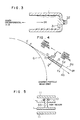
- SR beams 54a and 54b respectively stemming from points A1 and B1 on the charged partial beam orbit 56 reach end points A2 and B2, close to the insert plate 62, of the beam stabilizer 61.
- Line segments A2A1 and B2B1 are representative of tangents at the points A1 and B1 on the orbit 56, respectively, and coincide with the trace of the SR beams.
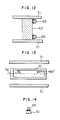
- upper and lower hooks 66 are provided on the interior surface of the vacuum chamber 51 and act to effect positioning of end corners of the beam stabilizer 61 and the insert plate 62.
- the height of each hook 66 is not so large as to bridge the vacuum chamber 51 but is designed to take a value which is sufficient for positioning of the beam stabilizer 61 and insert plate 62, measuring 3 to 5 mm, for example. Accordingly, the SR beam does not irradiate the hook 66 directly.
- the beam stabilizer 61 is hollowed to form a cross-sectionally rectangular cavity which has a small area irradiated with the synchrotron radiation and besides it is made of a copper material from which a small amount of gases is discharged under the irradiation of the synchrotron radiation. Accordingly, even with the beam stabilizers 61 disposed inside the vacuum chamber 51, the interior of the vacuum chamber can be maintained at high vacuum and lifetime of the charged particle beam can be prolonged.
- the beam stabilizer of copper is used to minimize the outgassing amount under the irradiation of the synchrotron radiation but the beam absorber made of aluminum may be used to attain substantially the same effect.
- the electrically conductive beam stabilizers are disposed at positions inside the bending section/vacuum chamber which are distant by a predetermined distance from the charged particle beam orbit toward the circumferential wall of the vacuum chamber, the bending section/vacuum chamber having a cross-sectional form which expands two-dimensionally can electrically be treated as a straight section beam duct having nearly a circular or elliptical cross-sectional form, so that the charged particle beam orbit can be made stable which would otherwise be distrubed by the induced wake field and consequently, the charged particle beam will not be attenuated by deviating from the orbit to the interior wall surface of the vacuum chamber and its lifetime can be prolonged.
Landscapes
- Physics & Mathematics (AREA)
- Engineering & Computer Science (AREA)
- Plasma & Fusion (AREA)
- Spectroscopy & Molecular Physics (AREA)
- Particle Accelerators (AREA)
Applications Claiming Priority (4)
| Application Number | Priority Date | Filing Date | Title |
|---|---|---|---|
| JP62060982A JP2515783B2 (ja) | 1987-03-18 | 1987-03-18 | シンクロトロン放射光発生装置 |
| JP60982/87 | 1987-03-18 | ||
| JP68899/87 | 1987-03-25 | ||
| JP6889987A JPS63236300A (ja) | 1987-03-25 | 1987-03-25 | シンクロトロン放射光装置 |
Publications (3)
| Publication Number | Publication Date |
|---|---|
| EP0282988A2 true EP0282988A2 (de) | 1988-09-21 |
| EP0282988A3 EP0282988A3 (en) | 1990-01-17 |
| EP0282988B1 EP0282988B1 (de) | 1994-03-02 |
Family
ID=26402035
Family Applications (1)
| Application Number | Title | Priority Date | Filing Date |
|---|---|---|---|
| EP88104169A Expired - Lifetime EP0282988B1 (de) | 1987-03-18 | 1988-03-16 | Synchrotron-Strahlungsquelle |
Country Status (3)
| Country | Link |
|---|---|
| US (1) | US4994753A (de) |
| EP (1) | EP0282988B1 (de) |
| DE (1) | DE3887996T2 (de) |
Cited By (1)
| Publication number | Priority date | Publication date | Assignee | Title |
|---|---|---|---|---|
| EP0306966A3 (en) * | 1987-09-11 | 1990-01-17 | Hitachi, Ltd. | Bending magnet |
Family Cites Families (4)
| Publication number | Priority date | Publication date | Assignee | Title |
|---|---|---|---|---|
| DE3148100A1 (de) * | 1981-12-04 | 1983-06-09 | Uwe Hanno Dr. 8050 Freising Trinks | "synchrotron-roentgenstrahlungsquelle" |
| GB8421867D0 (en) * | 1984-08-29 | 1984-10-03 | Oxford Instr Ltd | Devices for accelerating electrons |
| DE3703938A1 (de) * | 1986-02-12 | 1987-09-10 | Mitsubishi Electric Corp | Teilchenbeschleuniger |
| US4808941A (en) * | 1986-10-29 | 1989-02-28 | Siemens Aktiengesellschaft | Synchrotron with radiation absorber |
-
1988
- 1988-03-16 DE DE3887996T patent/DE3887996T2/de not_active Expired - Fee Related
- 1988-03-16 EP EP88104169A patent/EP0282988B1/de not_active Expired - Lifetime
- 1988-03-17 US US07/169,598 patent/US4994753A/en not_active Expired - Fee Related
Cited By (2)
| Publication number | Priority date | Publication date | Assignee | Title |
|---|---|---|---|---|
| EP0306966A3 (en) * | 1987-09-11 | 1990-01-17 | Hitachi, Ltd. | Bending magnet |
| US4996496A (en) * | 1987-09-11 | 1991-02-26 | Hitachi, Ltd. | Bending magnet |
Also Published As
| Publication number | Publication date |
|---|---|
| US4994753A (en) | 1991-02-19 |
| EP0282988A3 (en) | 1990-01-17 |
| DE3887996T2 (de) | 1994-08-11 |
| EP0282988B1 (de) | 1994-03-02 |
| DE3887996D1 (de) | 1994-04-07 |
Similar Documents
| Publication | Publication Date | Title |
|---|---|---|
| US5177448A (en) | Synchrotron radiation source with beam stabilizers | |
| US10856445B2 (en) | Electronic component housing apparatus and electronic device | |
| US20150380198A1 (en) | Magnetron | |
| KR100316069B1 (ko) | 고성능 수평 확산로 시스템 | |
| US4034251A (en) | Transmission x-ray tube | |
| CN102007654A (zh) | 具有挠性外壳的扩散冷却的co2激光器 | |
| JP7089396B2 (ja) | X線発生装置 | |
| JPS6338121B2 (de) | ||
| EP0282988A2 (de) | Synchrotron-Strahlungsquelle | |
| US3794879A (en) | Microwave magnetron | |
| US12191106B2 (en) | Method for manufacturing industrial magnetron | |
| US2826624A (en) | Vapor shield for induction furnace | |
| US3739225A (en) | Microwave magnetron | |
| JP2515783B2 (ja) | シンクロトロン放射光発生装置 | |
| SU1434508A1 (ru) | Рентгеновска трубка | |
| CN222636868U (zh) | 电子帘真空装置 | |
| EP0278504A2 (de) | Synchrotron-Strahlungsquelle | |
| JPH0685395B2 (ja) | 半導体製造装置等における加熱装置 | |
| EP0315134B1 (de) | Synchrotronstrahlungsquelle und Methode für ihre Herstellung | |
| JP2001257201A (ja) | マイクロ波プラズマ処理装置 | |
| US20250081416A1 (en) | Power supply device | |
| CN118471576A (zh) | 电子帘真空装置 | |
| CN113616937B (zh) | 放疗靶结构及放射治疗设备 | |
| JP2002014200A (ja) | 粒子線等の取出窓構造 | |
| JPS6331182A (ja) | ガスレ−ザ−装置 |
Legal Events
| Date | Code | Title | Description |
|---|---|---|---|
| PUAI | Public reference made under article 153(3) epc to a published international application that has entered the european phase |
Free format text: ORIGINAL CODE: 0009012 |
|
| AK | Designated contracting states |
Kind code of ref document: A2 Designated state(s): CH DE FR GB LI SE |
|
| PUAL | Search report despatched |
Free format text: ORIGINAL CODE: 0009013 |
|
| AK | Designated contracting states |
Kind code of ref document: A3 Designated state(s): CH DE FR GB LI SE |
|
| 17P | Request for examination filed |
Effective date: 19900119 |
|
| 17Q | First examination report despatched |
Effective date: 19910325 |
|
| GRAA | (expected) grant |
Free format text: ORIGINAL CODE: 0009210 |
|
| RAP1 | Party data changed (applicant data changed or rights of an application transferred) |
Owner name: HITACHI ENGINEERING AND SERVICES CO., LTD. Owner name: NIPPON TELEGRAPH AND TELEPHONE CORPORATION Owner name: HITACHI, LTD. |
|
| AK | Designated contracting states |
Kind code of ref document: B1 Designated state(s): CH DE FR GB LI SE |
|
| REF | Corresponds to: |
Ref document number: 3887996 Country of ref document: DE Date of ref document: 19940407 |
|
| ET | Fr: translation filed | ||
| PLBE | No opposition filed within time limit |
Free format text: ORIGINAL CODE: 0009261 |
|
| STAA | Information on the status of an ep patent application or granted ep patent |
Free format text: STATUS: NO OPPOSITION FILED WITHIN TIME LIMIT |
|
| EAL | Se: european patent in force in sweden |
Ref document number: 88104169.3 |
|
| 26N | No opposition filed | ||
| PGFP | Annual fee paid to national office [announced via postgrant information from national office to epo] |
Ref country code: FR Payment date: 20010112 Year of fee payment: 14 |
|
| PGFP | Annual fee paid to national office [announced via postgrant information from national office to epo] |
Ref country code: SE Payment date: 20010119 Year of fee payment: 14 |
|
| PGFP | Annual fee paid to national office [announced via postgrant information from national office to epo] |
Ref country code: GB Payment date: 20010306 Year of fee payment: 14 |
|
| PGFP | Annual fee paid to national office [announced via postgrant information from national office to epo] |
Ref country code: CH Payment date: 20010529 Year of fee payment: 14 |
|
| PGFP | Annual fee paid to national office [announced via postgrant information from national office to epo] |
Ref country code: DE Payment date: 20010530 Year of fee payment: 14 |
|
| REG | Reference to a national code |
Ref country code: GB Ref legal event code: IF02 |
|
| PG25 | Lapsed in a contracting state [announced via postgrant information from national office to epo] |
Ref country code: GB Free format text: LAPSE BECAUSE OF NON-PAYMENT OF DUE FEES Effective date: 20020316 |
|
| PG25 | Lapsed in a contracting state [announced via postgrant information from national office to epo] |
Ref country code: SE Free format text: LAPSE BECAUSE OF NON-PAYMENT OF DUE FEES Effective date: 20020317 |
|
| PG25 | Lapsed in a contracting state [announced via postgrant information from national office to epo] |
Ref country code: LI Free format text: LAPSE BECAUSE OF NON-PAYMENT OF DUE FEES Effective date: 20020331 Ref country code: CH Free format text: LAPSE BECAUSE OF NON-PAYMENT OF DUE FEES Effective date: 20020331 |
|
| PG25 | Lapsed in a contracting state [announced via postgrant information from national office to epo] |
Ref country code: DE Free format text: LAPSE BECAUSE OF NON-PAYMENT OF DUE FEES Effective date: 20021001 |
|
| EUG | Se: european patent has lapsed |
Ref document number: 88104169.3 |
|
| GBPC | Gb: european patent ceased through non-payment of renewal fee |
Effective date: 20020316 |
|
| REG | Reference to a national code |
Ref country code: CH Ref legal event code: PL |
|
| PG25 | Lapsed in a contracting state [announced via postgrant information from national office to epo] |
Ref country code: FR Free format text: LAPSE BECAUSE OF NON-PAYMENT OF DUE FEES Effective date: 20021129 |
|
| REG | Reference to a national code |
Ref country code: FR Ref legal event code: ST |