EP0282999A2 - Assemblage à bras oscillant remplaçable pour système de moulage par injection - Google Patents
Assemblage à bras oscillant remplaçable pour système de moulage par injection Download PDFInfo
- Publication number
- EP0282999A2 EP0282999A2 EP88104193A EP88104193A EP0282999A2 EP 0282999 A2 EP0282999 A2 EP 0282999A2 EP 88104193 A EP88104193 A EP 88104193A EP 88104193 A EP88104193 A EP 88104193A EP 0282999 A2 EP0282999 A2 EP 0282999A2
- Authority
- EP
- European Patent Office
- Prior art keywords
- rocker arm
- valve pin
- bore
- injection molding
- molding system
- Prior art date
- Legal status (The legal status is an assumption and is not a legal conclusion. Google has not performed a legal analysis and makes no representation as to the accuracy of the status listed.)
- Withdrawn
Links
Images


Classifications
-
- B—PERFORMING OPERATIONS; TRANSPORTING
- B29—WORKING OF PLASTICS; WORKING OF SUBSTANCES IN A PLASTIC STATE IN GENERAL
- B29C—SHAPING OR JOINING OF PLASTICS; SHAPING OF MATERIAL IN A PLASTIC STATE, NOT OTHERWISE PROVIDED FOR; AFTER-TREATMENT OF THE SHAPED PRODUCTS, e.g. REPAIRING
- B29C45/00—Injection moulding, i.e. forcing the required volume of moulding material through a nozzle into a closed mould; Apparatus therefor
- B29C45/17—Component parts, details or accessories; Auxiliary operations
- B29C45/26—Moulds
- B29C45/27—Sprue channels ; Runner channels or runner nozzles
- B29C45/28—Closure devices therefor
- B29C45/2806—Closure devices therefor consisting of needle valve systems
- B29C45/281—Drive means therefor
-
- B—PERFORMING OPERATIONS; TRANSPORTING
- B29—WORKING OF PLASTICS; WORKING OF SUBSTANCES IN A PLASTIC STATE IN GENERAL
- B29C—SHAPING OR JOINING OF PLASTICS; SHAPING OF MATERIAL IN A PLASTIC STATE, NOT OTHERWISE PROVIDED FOR; AFTER-TREATMENT OF THE SHAPED PRODUCTS, e.g. REPAIRING
- B29C45/00—Injection moulding, i.e. forcing the required volume of moulding material through a nozzle into a closed mould; Apparatus therefor
- B29C45/17—Component parts, details or accessories; Auxiliary operations
- B29C45/26—Moulds
- B29C45/27—Sprue channels ; Runner channels or runner nozzles
- B29C45/28—Closure devices therefor
- B29C45/2806—Closure devices therefor consisting of needle valve systems
- B29C45/281—Drive means therefor
- B29C2045/2834—Needle valves driven by a lever
Definitions
- This invention relates generally to valve gated injection molding, and more particularly to a system having an easily replaceable rocker arm assembly.
- the invention provides a valve gated injection molding system having at least one heated nozzle seated in a mold core, the nozzle having a bore in alignment with a gate extending from a melt passage to a cavity, a rocker arm assembly with a pivoted rocker arm having inner and outer elongated ends, an elongated valve pin having a driven end and a tip end, the valve pin extending through the bore of the nozzle with the driven end being operatively connected to the inner end of the rocker arm and the outer end of the rocker arm being operatively connected to valve pin actuating mechanism, whereby the valve pin is reciprocated between a retracted open position and a closed position wherein the tip end of the valve pin is seated in the gate, the improvement wherein, the rocker arm assembly comprises a rocker arm support member and the elongated rocker arm which is pivotally mounted on the support member, the rocker arm assembly being mounted in a bore in the mold core, having an inner and an outer end, the rocker arm assembly with a rocker arm
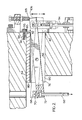
- Figure 1 shows a portion of a valve gated injection molding system having a number of nozzles 10 mounted directly to one side of an elongated manifold 12.
- the nozzles 10 are each located in a well 14 in the mold core 16 to convey melt from the manifold 12 to a common cavity 18.
- the manifold 12 is located relative to the mold core 16 by a central locating ring 20 seated between them, and has a longitudinal melt bore 22.
- the longitudinal melt bore 22 branches out to a number of outlets 24 and extends from a heated melt conveying tube 26 which is bolted to the manifold 12.
- the melt conveying tube 26 has a central bore 28 to receive pressurized melt from a molding machine (not shown) through a recessed inlet 30.
- the manifold 12 is heated to a predetermined temperature by electric plate heater 32 which is bolted to the other side surface of the manifold 12.
- Each nozzle 10 has a generally cylindrical outer surface 34 and valve pin bore 36 extending centrally therethrough.
- the valve pin bore 36 has an enlarged mouth 38 which is threaded to securely receive a tip insert 40.
- the tip insert 40 has a tapered central bore 42 in alignment with the valve pin bore 36 and a cylindrical nose portion 44 which is received in an opening 46 through the core 16, whereby the central bore 42 of the tip insert 40 forms a gate 48 leading to the cavity 18.
- Each nozzle 10 has a side portion 50 which is bolted to the manifold 12, as described in the applicants' Canadian patent application serial no. 529,897 entitled "Injection Molding System Having Manifold with Side Mounted Nozzles and Method” filed February 17, 1987.
- the nozzle 10 has a melt channel 52 with a generally longitudinal portion 54 and a lateral portion 56 which connects to an outlet 24 from the manifold.
- the longitudinal portion 54 extends parallel to but offset from the central valve pin bore 36.
- Each nozzle 10 also has two cartridge heaters 58 to maintain the temperature of the nozzle 10 at a predetermined level.
- the generally cylindrical outer surface 34 of the nozzle is smaller in diameter than the well 14 to provide an insulative air space 60 between the heated nozzle 10 and the surrounding core 16 which is cooled by cooling water flowing through cooling conduits 62.
- Locating screws 64 are spaced around the circumference of the nozzle 10 to accurately locate it in the well 14.
- the forward end of the nozzle 10 is accurately located by the nose portion 44 of the tip insert 40 received in the opening 46 in the core 16, and the rear end of the nozzle is located by the locating screws 64. Securing the nozzle 10 to the side of the manifold by bolts allows slight lateral movement between them to provide for thermal expansion of the manifold 12 when the system is first heated up.
- An elongated valve pin 66 is located in the central valve pin bore 36 of each nozzle 10.
- Each valve pin 66 has a driven end 68 with an enlarged head 70 extending from the stem 72, and a tapered tip end 74.
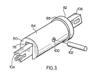
- the rocker arm assembly includes a rocker arm 76 which is pivotally mounted in a downwardly open groove 78 which extends between the inner end 80 and the outer end 82 of an elongated cylindrical support housing 84.
- the housing 84 is made the right size to slide into a cylindrical bore 86 which is drilled through the mold core 16 from an outer end 88 to an inner end 90.
- the support housing 84 has a collar 85 at its outer end 82 which abuts against a shoulder 87 and, during use, the housing 84 is securely retained in position by a retaining screw 92 which is screwed in a threaded hole 94 in the mold core 16 with a head 96 which engages the outer end 82 of the housing 84.
- the rocker arm 76 and the support housing 84 each have transverse holes 98,100 which receive a pivot pin 102 which pivotally mounts the rocker arm 76 on the support housing 84.
- the rocker arm 76 has an inner end 104 which engages the driven end 68 of the valve pin 66 and an outer end 106 which is connected to hydraulic actuating mechanism 108.
- the actuating mechanism is of a type well known in the art, similar to that disclosed in U.S. patent no. 4,468,191 to Gellert which issued August 28, 1984. It has a piston 110 which reciprocates in a cylinder.
- the piston 110 has an adjustable length connecting rod 114 which is connected to the outer end 106 of the rocker arm 76 by a removable pin 116. Controlled hydraulic pressure applied to the actuating mechanism on opposite sides of the piston 110 drives the valve pin 66 through the rocker arm 76 between a forward closed position in which the tip end 74 is seated in the gate 48 and a rectracted open position.
- the inner end 104 of the rocker arm 76 is shaped to engage the head 70 of the valve pin 66 when the actuating mechanism is slid into the operating position in the bore 86, and to disengage it when it is slid out.
- the inner end 104 of the rocker arm 76 has an inwardly open slot 118 which is formed between upper and lower lips 120,122 to receive the enlarged head 70 of the valve pin 66.
- the lower lip 122 is formed of a pair of spaced fingers 124 which form an inwardly open channel 126 between them to receive the stem 72 of the valve pin 66.
- the support housing 84 is made of steel and the rocker arm 76 is made of a tool steel such as H13 to withstand stress and wear.
- melt is then introduced into the manifold melt bore 22 by a molding machine (not shown) positioned at the recessed central inlet 30.
- Melt pressure is controlled according to a predetermined cycle in conjunction with the application of controlled hydraulic pressure to the actuating mechanism, in a conventional manner. With each valve pin 66 in the retracted open position, the melt flows through the gate 48 and fills the cavity 18.
- injection pressure is held momentarily to pack and hydraulic pressure is then applied to pivot the rocker arm 76 to drive the valve pin 66 to the forward closed position with the tip end 74 of the valve pin 66 seated in the gate 48.
- the injection pressure is then released and this position is held for a short cooling period before the mold is opened for ejection.
- the mold is closed and hydraulic pressure reapplied to pivot the rocker arm 76 to draw the valve pin 66 to the retracted open position.
- Melt injection pressure is reapplied to refill the cavity, and the molding cycle is repeated continuously in a uniform cycle, depending on the size and shape of the cavity and the type of material being molded.
- the rocker arm assembly if the rocker arm assembly malfunctions or becomes worn, it can quickly and easily be replaced.
- the retaining screw 92 and the connecting rod pin 116 are removed.
- the rocker arm 76 and the support housing 84 are together withdrawn out of the cylindrical bore 86 through the outer end 90. As may be seen, this disengages the inner end 104 of the rocker arm 76 from the head 70 of the valve pin 66. If necessary, the valve pin can then also be removed through an aligned access opening 130 drilled in the mold core 16. If it is necessary to replace only the rocker arm 76 or the support housing 84, they can easily be separated by removing the pivot pin 102.
- Figure 5 illustrates a slightly modified embodiment of the invention in which the head 70 of the enlarged valve pin 66 is rod-shaped. However, it is received in the slot 118 between the upper and lower lips 120,122 of the inner end 104 of the rocker arm as previously described. Otherwise, the system and its operation is the same as that described above and need not be repeated.
- the system can have various mold configurations and the rocker arm assembly can be mounted in a back plate or similar mold component.
- the actuating mechanism 108 can be pneumatically actuated and can be mounted in a variety of arrangements.
- the rocker arm support housing or member 108 can have various structures which pivotally support the rocker arm 76 and is removably received in the bore 86.
Landscapes
- Engineering & Computer Science (AREA)
- Manufacturing & Machinery (AREA)
- Mechanical Engineering (AREA)
- Moulds For Moulding Plastics Or The Like (AREA)
- Injection Moulding Of Plastics Or The Like (AREA)
Applications Claiming Priority (2)
| Application Number | Priority Date | Filing Date | Title |
|---|---|---|---|
| CA532489 | 1987-03-19 | ||
| CA000532489A CA1261579A (fr) | 1987-03-19 | 1987-03-19 | Genouillere remplacable pour systeme de moulage par injection |
Publications (2)
| Publication Number | Publication Date |
|---|---|
| EP0282999A2 true EP0282999A2 (fr) | 1988-09-21 |
| EP0282999A3 EP0282999A3 (fr) | 1990-03-07 |
Family
ID=4135228
Family Applications (1)
| Application Number | Title | Priority Date | Filing Date |
|---|---|---|---|
| EP88104193A Withdrawn EP0282999A3 (fr) | 1987-03-19 | 1988-03-16 | Assemblage à bras oscillant remplaçable pour système de moulage par injection |
Country Status (3)
| Country | Link |
|---|---|
| US (1) | US4712995A (fr) |
| EP (1) | EP0282999A3 (fr) |
| CA (1) | CA1261579A (fr) |
Cited By (7)
| Publication number | Priority date | Publication date | Assignee | Title |
|---|---|---|---|---|
| EP0374346A3 (fr) * | 1988-12-21 | 1991-01-09 | Otto Männer | Buse à obturateur à aiguille pour moules d'injection |
| EP0520345A3 (en) * | 1991-06-28 | 1993-05-05 | Acrilux Spa | Injection nozzle for an injection mould |
| EP0832729A1 (fr) * | 1996-09-30 | 1998-04-01 | EUROTOOL Beheer B.V. | Dispositif de buse à obturation pour moulage par injection |
| EP0836925A1 (fr) * | 1996-10-09 | 1998-04-22 | EUROTOOL Beheer B.V. | Dispositif de buse à obturation pour moulage par injection |
| US6893249B2 (en) | 2001-09-07 | 2005-05-17 | Mold-Masters Limited | Valve pin actuating mechanism |
| US7048532B2 (en) | 2002-12-02 | 2006-05-23 | Mold-Masters Limited | Stroke limiter for valve pin actuating mechanism |
| US7131834B2 (en) | 2002-08-14 | 2006-11-07 | Mold-Masters Ltd. | Valve pin adjustment device |
Families Citing this family (29)
| Publication number | Priority date | Publication date | Assignee | Title |
|---|---|---|---|---|
| CH677210A5 (fr) * | 1987-12-10 | 1991-04-30 | Otto Hofstetter Ag Werkzeug Un | |
| CA1292848C (fr) * | 1989-02-14 | 1991-12-10 | Jobst Ulrich Gellert | Systeme de moulage par injection comprenant une soupape avec partie isolee cannelee |
| CA1309819C (fr) * | 1989-06-02 | 1992-11-10 | Jobst Ulrich Gellert | Dispositif de moulage par injection a bague fendue de commande de robinet |
| JPH0767715B2 (ja) * | 1990-11-20 | 1995-07-26 | 三晶技研株式会社 | ホットランナ式合成樹脂金型 |
| CA2037186C (fr) * | 1991-02-27 | 2002-07-30 | Jobst Ulrich Gellert | Sonde comprennant un logement longitudinal pour couple thermoelectrique et un element chauffant excentrique, dans un systeme de moulage par injection |
| US5539857A (en) * | 1994-01-24 | 1996-07-23 | Caco Pacific Corporation | Heater block for injection molding with removable heat conductive member in groove in heater block |
| US5635227A (en) * | 1995-06-07 | 1997-06-03 | R & D Tool And Engineering, Inc. | Replaceable air cylinder unit and valve gate for injection molding machines |
| FR2747337B1 (fr) * | 1996-04-10 | 1998-06-26 | Atek Dev | Dispositif de commande d'un obturateur de buse d'injection de matiere plastique |
| JP3028407B2 (ja) * | 1996-05-20 | 2000-04-04 | 株式会社吉野工業所 | 射出成形型用バルブゲート装置 |
| US6056536A (en) * | 1997-03-20 | 2000-05-02 | Husky Injection Molding Systems Ltd. | Valve gating apparatus for injection molding |
| US5855934A (en) * | 1997-05-27 | 1999-01-05 | Tradesco Mold Limited | Valve pin actuator |
| US6174158B1 (en) | 1997-11-19 | 2001-01-16 | Incoe Corporation | Injection molding shut-off bushing with separate material flow path |
| US5895669A (en) * | 1997-06-13 | 1999-04-20 | Incoe Corporation | Injection molding shut-off bushing with separate material flow path |
| US6099292A (en) * | 1997-10-22 | 2000-08-08 | Caco Pacific Corporation | Heater block with unitized removable heat conductive member |
| US6159000A (en) * | 1999-03-12 | 2000-12-12 | Husky Injection Molding Systems Ltd. | Valve gated injection molding device |
| US6755641B1 (en) * | 2000-09-01 | 2004-06-29 | Mold-Masters Limited | Stack injection molding apparatus with separately actuated arrays of valve gates |
| FR2821010A1 (fr) * | 2001-02-19 | 2002-08-23 | Plastiques Appliquees Epa Et | Dispositif de commande du mecanisme d'obturation d'une buse d'injection dans le domaine de l'injection des matieres plastiques et silicones |
| US20030008034A1 (en) * | 2001-07-06 | 2003-01-09 | Husky Injection Molding, Ltd. | Method and apparatus for injection molding articles |
| US7156651B2 (en) * | 2001-07-06 | 2007-01-02 | Husky Injection Molding Systems Ltd. | Apparatus for injection molding articles |
| CA2357083C (fr) * | 2001-09-07 | 2009-02-03 | Mold-Masters Limited | Mecanisme de manoeuvre de tige de soupape |
| US7014455B2 (en) | 2002-03-14 | 2006-03-21 | Mold-Masters Limited | Valve-gated injection molding system with side-mounted actuator |
| US7722351B2 (en) * | 2007-10-22 | 2010-05-25 | Mold-Masters (2007) Limited | Injection molding apparatus having magnetic valve pin coupling |
| FR2939353B1 (fr) * | 2008-12-09 | 2017-04-14 | Runipsys Europe | Systeme d'injection de matiere thermoplastique |
| FR2946914B1 (fr) | 2009-06-17 | 2011-06-17 | Runipsys Europ | Buse et systeme d'injection de matiere thermoplastique |
| ITTO20120578A1 (it) * | 2012-06-28 | 2013-12-29 | Inglass Spa | Apparecchiatura di stampaggio ad iniezione di materie plastiche |
| CH706910A2 (de) | 2012-09-04 | 2014-03-14 | Schoettli Ag | Heisskanaldüse zum Einspritzen von thermoplastischem Kunststoff in ein Formwerkzeug. |
| DE102014210335A1 (de) * | 2014-06-02 | 2015-12-03 | AWETIS Engineering + Manufacturing GmbH | Nadelverschlussdüsensystem |
| EP3009251B1 (fr) * | 2014-10-15 | 2021-06-23 | Inglass S.p.A. | Appareil de moulage par injection de matière plastique |
| US20220203589A1 (en) * | 2020-12-24 | 2022-06-30 | Next Chapter Manufacturing Corporation | Vented Mold Pin |
Family Cites Families (6)
| Publication number | Priority date | Publication date | Assignee | Title |
|---|---|---|---|---|
| US2773284A (en) * | 1953-03-13 | 1956-12-11 | Columbus Plastic Products Inc | Die construction for pressure injection molding machines |
| US3488810A (en) * | 1967-03-17 | 1970-01-13 | Jobst U Gellert | Valve-gated mold construction |
| CA1032317A (fr) * | 1975-04-10 | 1978-06-06 | Jobst U. Gellert | Mecanisme a opercule pour le moulage par injection |
| CA1029162A (fr) * | 1975-04-10 | 1978-04-11 | Jobst U. Gellert | Manchon d'etancheite pour moule d'injection a soupape d'admission |
| CA1097873A (fr) * | 1978-12-14 | 1981-03-24 | Jobst U. Gellert | Traduction non-disponible |
| CA1193818A (fr) * | 1983-03-24 | 1985-09-24 | Jobst U. Gellert | Systeme de moulage par injection avec commande hydraulique a raccordements alternes |
-
1987
- 1987-03-19 CA CA000532489A patent/CA1261579A/fr not_active Expired
- 1987-04-01 US US07/032,549 patent/US4712995A/en not_active Expired - Fee Related
-
1988
- 1988-03-16 EP EP88104193A patent/EP0282999A3/fr not_active Withdrawn
Cited By (10)
| Publication number | Priority date | Publication date | Assignee | Title |
|---|---|---|---|---|
| EP0374346A3 (fr) * | 1988-12-21 | 1991-01-09 | Otto Männer | Buse à obturateur à aiguille pour moules d'injection |
| EP0520345A3 (en) * | 1991-06-28 | 1993-05-05 | Acrilux Spa | Injection nozzle for an injection mould |
| US5511968A (en) * | 1991-06-28 | 1996-04-30 | Acrilux S.P.A. | Injection nozzle for a mould |
| EP0832729A1 (fr) * | 1996-09-30 | 1998-04-01 | EUROTOOL Beheer B.V. | Dispositif de buse à obturation pour moulage par injection |
| US5984661A (en) * | 1996-09-30 | 1999-11-16 | Eurotool Beheer B.V. | Valve-gated injection moulding device |
| EP0836925A1 (fr) * | 1996-10-09 | 1998-04-22 | EUROTOOL Beheer B.V. | Dispositif de buse à obturation pour moulage par injection |
| US5902614A (en) * | 1996-10-09 | 1999-05-11 | Eurotool Beheer B.V. | Valve-gated injection moulding device |
| US6893249B2 (en) | 2001-09-07 | 2005-05-17 | Mold-Masters Limited | Valve pin actuating mechanism |
| US7131834B2 (en) | 2002-08-14 | 2006-11-07 | Mold-Masters Ltd. | Valve pin adjustment device |
| US7048532B2 (en) | 2002-12-02 | 2006-05-23 | Mold-Masters Limited | Stroke limiter for valve pin actuating mechanism |
Also Published As
| Publication number | Publication date |
|---|---|
| US4712995A (en) | 1987-12-15 |
| EP0282999A3 (fr) | 1990-03-07 |
| CA1261579A (fr) | 1989-09-26 |
Similar Documents
| Publication | Publication Date | Title |
|---|---|---|
| US4712995A (en) | Replaceable rocker arm assembly for injection molding system | |
| EP0873841B1 (fr) | Buse d'injection avec insert d'orifice d'injection en une pièce pour support d'une soupape cylindrique | |
| EP0385175B1 (fr) | Système de moulage par injection avec flux de gaz à travers l'ouverture de la valve | |
| CA1252973A (fr) | Bloc collecteur lateral pour l'orientation variable d'un buse d'injection de moulage | |
| US7182591B2 (en) | Injection nozzle system and injection molding machine incorporating same | |
| EP0264725B1 (fr) | Douille d'alimentation double pour le moulage par injection à plusieurs cavités | |
| US5049062A (en) | Injection molding system having spring biased nozzles | |
| US4530654A (en) | Injection molding peripheral opening core ring gate | |
| EP0614743B1 (fr) | Insert de buse d'injection avec pales de centrage pour valve | |
| EP0657270B1 (fr) | Dispositif de moulage par injection avec buse à obturation avec un ressort dans le piston | |
| EP0279400A2 (fr) | Système de moulage par injection avec distributeur à buses d'injection à montage latéral et procédé | |
| EP0916470B1 (fr) | Machine à mouler par injection à entrée d'injection latérale avec distributeur actionné | |
| US4755131A (en) | Fluid cooled hydraulic actuating mechanism for single cavity injection molding | |
| EP0153554A2 (fr) | Dispositif de buse à obturation pour moulage par injection | |
| US5037598A (en) | Reciprocating heated nozzle | |
| US6162044A (en) | Multi-cavity injection molding apparatus splitting melt near nozzle front | |
| EP0373293B1 (fr) | Mécanisme de commande à crémaillère pour l'aiguille d'obturateur de moulage par injection | |
| US4729733A (en) | Dual feed single cavity injection molding system | |
| WO2001078961A9 (fr) | Systeme de buse a injection et machine a mouler par injection munie d'un tel systeme | |
| USRE39935E1 (en) | Multi-cavity injection molding apparatus splitting melt near nozzle front | |
| CA1311893C (fr) | Machine a injection sous pression a ecoulement gazeux au travers des moules |
Legal Events
| Date | Code | Title | Description |
|---|---|---|---|
| PUAI | Public reference made under article 153(3) epc to a published international application that has entered the european phase |
Free format text: ORIGINAL CODE: 0009012 |
|
| AK | Designated contracting states |
Kind code of ref document: A2 Designated state(s): AT BE CH DE ES FR GB GR IT LI LU NL SE |
|
| PUAL | Search report despatched |
Free format text: ORIGINAL CODE: 0009013 |
|
| AK | Designated contracting states |
Kind code of ref document: A3 Designated state(s): AT BE CH DE ES FR GB GR IT LI LU NL SE |
|
| STAA | Information on the status of an ep patent application or granted ep patent |
Free format text: STATUS: THE APPLICATION IS DEEMED TO BE WITHDRAWN |
|
| 18D | Application deemed to be withdrawn |
Effective date: 19900910 |