EP0283013A2 - Agencement de connexion pour utilisation dans un système de transmission multiplex - Google Patents
Agencement de connexion pour utilisation dans un système de transmission multiplex Download PDFInfo
- Publication number
- EP0283013A2 EP0283013A2 EP88104259A EP88104259A EP0283013A2 EP 0283013 A2 EP0283013 A2 EP 0283013A2 EP 88104259 A EP88104259 A EP 88104259A EP 88104259 A EP88104259 A EP 88104259A EP 0283013 A2 EP0283013 A2 EP 0283013A2
- Authority
- EP
- European Patent Office
- Prior art keywords
- conductors
- multiplex transmission
- transmission terminal
- pair
- terminal
- Prior art date
- Legal status (The legal status is an assumption and is not a legal conclusion. Google has not performed a legal analysis and makes no representation as to the accuracy of the status listed.)
- Granted
Links
- 230000005540 biological transmission Effects 0.000 title claims abstract description 24
- 239000004020 conductor Substances 0.000 claims abstract description 42
- 238000009413 insulation Methods 0.000 claims description 6
- 230000008878 coupling Effects 0.000 claims description 5
- 238000010168 coupling process Methods 0.000 claims description 5
- 238000005859 coupling reaction Methods 0.000 claims description 5
- 230000000295 complement effect Effects 0.000 description 1
- 238000010586 diagram Methods 0.000 description 1
- 230000006698 induction Effects 0.000 description 1
- 239000012774 insulation material Substances 0.000 description 1
- 239000000463 material Substances 0.000 description 1
- 239000011347 resin Substances 0.000 description 1
- 229920005989 resin Polymers 0.000 description 1
Images


Classifications
-
- H—ELECTRICITY
- H01—ELECTRIC ELEMENTS
- H01R—ELECTRICALLY-CONDUCTIVE CONNECTIONS; STRUCTURAL ASSOCIATIONS OF A PLURALITY OF MUTUALLY-INSULATED ELECTRICAL CONNECTING ELEMENTS; COUPLING DEVICES; CURRENT COLLECTORS
- H01R9/00—Structural associations of a plurality of mutually-insulated electrical connecting elements, e.g. terminal strips or terminal blocks; Terminals or binding posts mounted upon a base or in a case; Bases therefor
- H01R9/03—Connectors arranged to contact a plurality of the conductors of a multiconductor cable, e.g. tapping connections
- H01R9/031—Connectors arranged to contact a plurality of the conductors of a multiconductor cable, e.g. tapping connections for multiphase cables, e.g. with contact members penetrating insulation of a plurality of conductors
Definitions
- the present invention relates to a multiplex terminal arrangement for a multidrop connection used in a multiplex transmission terminal for an industrial field or vehicle system.
- Fig. 1 shows an example of a multiplex transmission system using a multidrop connection system.
- 101 and 102 denote power transmission lines for supplying power to terminals 105 and 106 and 103 and 104 denote data transmission lines for transmitting data information to the terminals 105 and 106.
- the respective terminals 105 and 106 are provided with actuators 107 and 108 such as an electric motor or display lamp which are activated by the data information in addition to various switches 109 and 110 for inputting the data information.
- the power lines 101 and 102 and data lines 103 and 104 are connected to the respective terminals 105 and 106 by means of one or more separate connectors.
- An essential object of the present invention is to provide a multiplex transmission terminal which is easily mounted on a cable assembly and each connecting end of the multiplex transmission terminal can be easily connected with the cable assembly without any cable processing.
- Another object of the present invention is to provide a multiplex transmission terminal which can be mounted anywhere on the cable assembly as desired.
- a multiplex transmission terminal which is connected with a cable assembly having power conductors and signal conductors, said terminal comprising: a case body composed of a pair of case halves coupled by coupling means so that both of the halves are adapted to open and close around said coupling means; recess means defined inside said case body for accommodating a part of said cable assembly; at least one connecting member provided any one of the case halves, having an connecting end of said connecting member projected in said recess so that said connecting end is detachably contacted to any one of the conductors of said cable assembly.
- the cable unit comprises a pair of power supply conductors 1 and 2 of an elongated strip shape extending parallelly, being opposed each other.
- the two conductors 1 and 2 are separated as close as possible but assuring a desired withstand voltage.
- the cable unit further comprises a pair of signal conductors 3 and 4 closely disposed each other and extending parallelly at any one side of the power supply conductors 1 and 2.
- the respective distances between the signal conductor 3 and both of the power supply conductors 1 and 2 are made equal so as to prevent electrostatic induction from the power supply conductors 1 and 2.
- the respective distances between the signal conductor 4 and both of the power conductors 1 and 2 are also equal.
- the respective conductors 1 to 4 are covered with insulation material 11 (referred to as insulation layer hereinafter) as shown in Fig. 3. Although the conductors 1 to 4 are covered with insulation layer 11 over the whole length of the conductors, the terminal can be connected to the respective conductors 1 to 4 anywhere desired on the multiplex cable unit as mentioned below.
- insulation layer referred to as insulation layer hereinafter
- a terminal case 30 is composed of a top case half 30a and bottom case half 30b made of resin material.
- the terminal case 30 is shown in a transparent manner.
- Both of the case halves 30a and 30b are rotatably coupled by one or more hinges 19 so that both of the case halves 30a and 30b can be opened and closed around the hinge 19.
- a lock mechanism 20 is provided at the right hand portion of the outside of the terminal case 30.
- the locking mechanism 20 comprises a projection 20b projected outward from the bottom case half 30b and a resilient arm 20a projected from the top case half 30a in a generally L character shape so that the the resilient arm 20a can be releasably engaged beneath the lower part of the projection 20b.
- a printed circuit board 25 is accommodated in the top case half 30a and possible circuit arrangement including such as integrated circuit chip 23 or other necessary components for use in the multiplex transmission terminal is provided on the printed circuit board 25.
- Such circuit arrangement including the integrated circuit 23 and other components are respectively connected to the conductor patterns 24 formed on the printed circuit board 25 so as to provide a desired terminal circuit.
- Three pressing connector pins 15, 17 and 18 are downwardly projected from the printed circuit board 25 toward a recess 26 detail of which is explained later and one pressing type connector pin 16 is upwardly projected from the bottom case half 30b toward the recess 26.
- the connector pins 15 and 16 are so projected that the respective connector ends are opposed in the recess 26 and the connector pin 15 is connected to one of the printed circuit pattern 24.
- the connector pins 17 and 18 are connected to the other printed circuit patterns 29 and the connector pin 16 is connected to printed circuit pattern 24 through a conductor wire 27.
- the recess 26 is formed by a combination of elongated recesses 26x extending in a longitudinal direction of each of the case halves 30a and 30b on the respective inner surfaces 31 and 32.
- the recess 26x has such a shape as to conform to the outside shape of the top half or bottom half of the cable unit 10.
- the shape of the recess 26 is complementary to the outer shape of the multiplex cable unit 10, so that the multiplex cable unit 10 is accommodated in the recess 26 clamped by the inner surfaces 26y of the top half 30a or bottom half 30b which defines the recess 26x.
- the respective connector pins 15 to 18 have their end portions shaped into a fork shape with the ends sharpened so that when the terminal 30 is closed accommodating the cable unit 10, the ends of the respective connector pins 15 to 18 can penetrate the insulation layer 11 of the cable unit 10 and the ends of the connector pins can be pressed and contacted with the conductors 1, 2, 3 and 4 respectively.
- the connector pin 15 may be supported to the upper half 30a through a resilient member 27 so as to contact to a conductor resiliently.
- the top case half 30a and bottom case half 30b are opened around the hinge 19 as shown in Fig. 4.
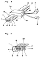
- the terminal 30 is mounted to the cable unit 10 by fitting the cable unit 10 in the recess 26 in such a manner that the power conductor portion 10f is laid in the generally flat shaped recess 26f and signal conductor portions 10r are laid in the round recesses 26r. Then the terminal 30 is closed as shown in Fig. 1 and Fig. 5 with the top half 30a and bottom half 30b locked in a closed manner by engaging the arm 20a with the projection 20b.
- Fig. 5 shows an example of mounting of the terminal 30 on the cable unit 10 with an electric motor 7 and a lamp 8 coupled to the terminal 30 through connection plug 60 so as to connect the motor 7 and lamp 8 to the connecting pins 21 projected from the side wall of the terminal 30.
- an advantage of the present invention is in that the terminal 30 can be mounted on the cable unit 10 by only clamping operation and it is easily to have the connector pins contacted with the conductors of the cable unit without any works to the cable such as cable cutting and end processing. Moreover, since no connector member is unnecessary on the cable side, the cost of connecting the terminal to the cable can be reduced.
- Another advantage of the present invention is in that the terminal can be mounted anywhere desired easily.
Landscapes
- Connections Effected By Soldering, Adhesion, Or Permanent Deformation (AREA)
- Connections By Means Of Piercing Elements, Nuts, Or Screws (AREA)
- Coupling Device And Connection With Printed Circuit (AREA)
- Multi-Conductor Connections (AREA)
Applications Claiming Priority (2)
| Application Number | Priority Date | Filing Date | Title |
|---|---|---|---|
| JP62063560A JPH0821438B2 (ja) | 1987-03-18 | 1987-03-18 | 多重伝送用タ−ミナル |
| JP63560/87 | 1987-03-18 |
Publications (3)
| Publication Number | Publication Date |
|---|---|
| EP0283013A2 true EP0283013A2 (fr) | 1988-09-21 |
| EP0283013A3 EP0283013A3 (en) | 1990-02-21 |
| EP0283013B1 EP0283013B1 (fr) | 1993-08-11 |
Family
ID=13232732
Family Applications (1)
| Application Number | Title | Priority Date | Filing Date |
|---|---|---|---|
| EP19880104259 Expired - Lifetime EP0283013B1 (fr) | 1987-03-18 | 1988-03-17 | Agencement de connexion pour utilisation dans un système de transmission multiplex |
Country Status (4)
| Country | Link |
|---|---|
| EP (1) | EP0283013B1 (fr) |
| JP (1) | JPH0821438B2 (fr) |
| CA (1) | CA1280479C (fr) |
| DE (1) | DE3883032T2 (fr) |
Cited By (14)
| Publication number | Priority date | Publication date | Assignee | Title |
|---|---|---|---|---|
| DE4320327C1 (de) * | 1993-04-13 | 1994-06-01 | Siemens Ag | Aktuatoren oder Sensoren zum Anschluß an eine Busleitung |
| WO1994024728A1 (fr) * | 1993-04-14 | 1994-10-27 | Siemens Aktiengesellschaft | Connecteur a encliqueter pour conducteurs electriques |
| DE19526809A1 (de) * | 1995-07-13 | 1997-01-16 | Siemens Ag | Bordnetz mit Multiplexsteuerung für Kraftfahrzeuge |
| DE19526806A1 (de) * | 1995-07-13 | 1997-01-16 | Siemens Ag | Bordnetz mit Multiplexsteuerung für Kraftfahrzeuge |
| DE29701828U1 (de) * | 1997-02-03 | 1997-04-10 | Siemens AG, 80333 München | Modul zum Anschluß eines Aktuators oder Sensors |
| EP0729199A3 (fr) * | 1995-02-24 | 1997-06-11 | Rehau Ag & Co | Composant électrique |
| EP0726623A3 (fr) * | 1995-02-07 | 1997-09-10 | Lumberg Karl Gmbh & Co | Dispositif de connexion pour le libre rétablissement d'une connexion électrique réutilisable, par exemple pour le branchement sur des lignes électriques à soins multiples |
| EP0821434A1 (fr) * | 1996-07-26 | 1998-01-28 | Siemens Aktiengesellschaft | Module pour raccorder des actionneurs et/ou de détecteurs |
| EP1450451A1 (fr) * | 2003-02-22 | 2004-08-25 | Briloner Leuchten GmbH | Adaptateur pour le contact d'une ligne d'alimentation à une barre conductrice pour un éclairage |
| US6960716B2 (en) | 2000-06-07 | 2005-11-01 | Sanyo Electric Co., Ltd. | Solar cell module, method of connecting solar cell module, method of installing solar cell module and method of grounding solar cell module |
| DE19646107B4 (de) * | 1995-12-12 | 2007-05-31 | Baumer Holding Ag | Kontaktierungsanordnung für mehradrige Flachkabel |
| EP3506434A1 (fr) * | 2018-01-02 | 2019-07-03 | OSRAM GmbH | Connecteur pour dispositifs d'éclairage linéaires et système d'éclairage comprenant ce connecteur |
| GB2578283A (en) * | 2018-09-17 | 2020-05-06 | Guzu Holdings Pty Ltd | Electrical connector |
| DE102020129353A1 (de) | 2020-11-06 | 2022-05-12 | Weidmüller Interface GmbH & Co. KG | Gehäuse mit einem Anschluss-System zur Realisierung von Abzweigungen an einer Mehrzahl durchgehender elektrischer Leiter |
Families Citing this family (2)
| Publication number | Priority date | Publication date | Assignee | Title |
|---|---|---|---|---|
| JP2753293B2 (ja) * | 1988-12-20 | 1998-05-18 | 株式会社フジクラ | 光ファイバ液体検知センサ |
| JPH0466775U (fr) * | 1990-10-23 | 1992-06-12 |
Family Cites Families (6)
| Publication number | Priority date | Publication date | Assignee | Title |
|---|---|---|---|---|
| JPS5274880A (en) * | 1975-12-19 | 1977-06-23 | Tai Fujita | Apparatus for connecting electric wire |
| JPS57188267U (fr) * | 1981-05-25 | 1982-11-29 | ||
| GB2136638A (en) * | 1983-03-09 | 1984-09-19 | Cannon Electric | Electrical connectors |
| JPS60149072U (ja) * | 1984-03-15 | 1985-10-03 | 日本碍子株式会社 | 絶縁電線把持具 |
| US4555158A (en) * | 1984-08-06 | 1985-11-26 | The Wallace Companies, Inc. | Modular connector and system containing the same |
| JPS6210368U (fr) * | 1985-07-03 | 1987-01-22 |
-
1987
- 1987-03-18 JP JP62063560A patent/JPH0821438B2/ja not_active Expired - Lifetime
-
1988
- 1988-03-17 DE DE19883883032 patent/DE3883032T2/de not_active Expired - Fee Related
- 1988-03-17 CA CA000561769A patent/CA1280479C/fr not_active Expired - Lifetime
- 1988-03-17 EP EP19880104259 patent/EP0283013B1/fr not_active Expired - Lifetime
Cited By (18)
| Publication number | Priority date | Publication date | Assignee | Title |
|---|---|---|---|---|
| DE4320327C1 (de) * | 1993-04-13 | 1994-06-01 | Siemens Ag | Aktuatoren oder Sensoren zum Anschluß an eine Busleitung |
| WO1994024728A1 (fr) * | 1993-04-14 | 1994-10-27 | Siemens Aktiengesellschaft | Connecteur a encliqueter pour conducteurs electriques |
| EP0726623A3 (fr) * | 1995-02-07 | 1997-09-10 | Lumberg Karl Gmbh & Co | Dispositif de connexion pour le libre rétablissement d'une connexion électrique réutilisable, par exemple pour le branchement sur des lignes électriques à soins multiples |
| EP0729199A3 (fr) * | 1995-02-24 | 1997-06-11 | Rehau Ag & Co | Composant électrique |
| DE19526809A1 (de) * | 1995-07-13 | 1997-01-16 | Siemens Ag | Bordnetz mit Multiplexsteuerung für Kraftfahrzeuge |
| DE19526806A1 (de) * | 1995-07-13 | 1997-01-16 | Siemens Ag | Bordnetz mit Multiplexsteuerung für Kraftfahrzeuge |
| DE19646107B4 (de) * | 1995-12-12 | 2007-05-31 | Baumer Holding Ag | Kontaktierungsanordnung für mehradrige Flachkabel |
| DE19646107C5 (de) * | 1995-12-12 | 2010-10-21 | Baumer Innotec Ag | Kontaktierungsanordnung für mehradrige Flachkabel |
| EP0821434A1 (fr) * | 1996-07-26 | 1998-01-28 | Siemens Aktiengesellschaft | Module pour raccorder des actionneurs et/ou de détecteurs |
| DE19630352C2 (de) * | 1996-07-26 | 2000-04-06 | Siemens Ag | Modul zum Anschluß von Aktoren und/oder Sensoren |
| DE29701828U1 (de) * | 1997-02-03 | 1997-04-10 | Siemens AG, 80333 München | Modul zum Anschluß eines Aktuators oder Sensors |
| US6024583A (en) * | 1997-02-03 | 2000-02-15 | Siemens Aktiengesellschaft | Module for connecting an actuator or sensor |
| US6960716B2 (en) | 2000-06-07 | 2005-11-01 | Sanyo Electric Co., Ltd. | Solar cell module, method of connecting solar cell module, method of installing solar cell module and method of grounding solar cell module |
| EP1450451A1 (fr) * | 2003-02-22 | 2004-08-25 | Briloner Leuchten GmbH | Adaptateur pour le contact d'une ligne d'alimentation à une barre conductrice pour un éclairage |
| EP3506434A1 (fr) * | 2018-01-02 | 2019-07-03 | OSRAM GmbH | Connecteur pour dispositifs d'éclairage linéaires et système d'éclairage comprenant ce connecteur |
| GB2578283A (en) * | 2018-09-17 | 2020-05-06 | Guzu Holdings Pty Ltd | Electrical connector |
| GB2578283B (en) * | 2018-09-17 | 2022-07-13 | Guzu Holdings Pty Ltd | Electrical connector |
| DE102020129353A1 (de) | 2020-11-06 | 2022-05-12 | Weidmüller Interface GmbH & Co. KG | Gehäuse mit einem Anschluss-System zur Realisierung von Abzweigungen an einer Mehrzahl durchgehender elektrischer Leiter |
Also Published As
| Publication number | Publication date |
|---|---|
| DE3883032T2 (de) | 1994-01-05 |
| DE3883032D1 (de) | 1993-09-16 |
| JPH0821438B2 (ja) | 1996-03-04 |
| EP0283013A3 (en) | 1990-02-21 |
| CA1280479C (fr) | 1991-02-19 |
| JPS63231885A (ja) | 1988-09-27 |
| EP0283013B1 (fr) | 1993-08-11 |
Similar Documents
| Publication | Publication Date | Title |
|---|---|---|
| CA1280479C (fr) | Terminal pour systeme de transmission multiplex | |
| EP0525604B1 (fr) | Connecteur électrique entrée-sortie | |
| US4725698A (en) | Electric connector device | |
| US5442170B1 (en) | Programmable cable adaptor for connecting different automobile computers to diagnostic equipment | |
| GB1493784A (en) | Connectors for flexible printed circuits | |
| EP0142952A3 (fr) | Connecteur électrique à charnière | |
| EP0283012B1 (fr) | Agencement de câble pour utilisation dans un système de transmission multiplex | |
| US5476393A (en) | Electrical connector for flat cable | |
| DE58905802D1 (de) | Elektrische Schutzkontaktsteckdose. | |
| GB2240671A (en) | Switched electrical connector | |
| GB2201306A (en) | Electrical plug terminals and cable clamp | |
| US5073125A (en) | Electrical connector comprising an intermediate connection element for connecting and disconnecting between a first and second connection element | |
| GB2136638A (en) | Electrical connectors | |
| US5664956A (en) | Activator plug | |
| GB2288287A (en) | Electrical connector | |
| GB2237455A (en) | Branching electric connector | |
| US6249438B1 (en) | Electrical device having a plug outlet | |
| US5169339A (en) | Electrical connector | |
| JPH0231742Y2 (fr) | ||
| JPH0625900Y2 (ja) | 抵抗接続端子付バスライン接続用レセプタクル | |
| HU209093B (en) | Gear-shift lever particularly for the steering-post switch of vehicles | |
| KR920002635Y1 (ko) | 접속기 장치 | |
| JPS6161235B2 (fr) | ||
| JPH0231741Y2 (fr) | ||
| EP0977325B1 (fr) | Une unité prise-interrupteur |
Legal Events
| Date | Code | Title | Description |
|---|---|---|---|
| PUAI | Public reference made under article 153(3) epc to a published international application that has entered the european phase |
Free format text: ORIGINAL CODE: 0009012 |
|
| AK | Designated contracting states |
Kind code of ref document: A2 Designated state(s): DE FR GB IT |
|
| PUAL | Search report despatched |
Free format text: ORIGINAL CODE: 0009013 |
|
| AK | Designated contracting states |
Kind code of ref document: A3 Designated state(s): DE FR GB IT |
|
| 17P | Request for examination filed |
Effective date: 19900220 |
|
| 17Q | First examination report despatched |
Effective date: 19920109 |
|
| GRAA | (expected) grant |
Free format text: ORIGINAL CODE: 0009210 |
|
| AK | Designated contracting states |
Kind code of ref document: B1 Designated state(s): DE FR GB IT |
|
| REF | Corresponds to: |
Ref document number: 3883032 Country of ref document: DE Date of ref document: 19930916 |
|
| ITF | It: translation for a ep patent filed | ||
| ET | Fr: translation filed | ||
| PLBE | No opposition filed within time limit |
Free format text: ORIGINAL CODE: 0009261 |
|
| STAA | Information on the status of an ep patent application or granted ep patent |
Free format text: STATUS: NO OPPOSITION FILED WITHIN TIME LIMIT |
|
| 26N | No opposition filed | ||
| REG | Reference to a national code |
Ref country code: GB Ref legal event code: IF02 |
|
| PGFP | Annual fee paid to national office [announced via postgrant information from national office to epo] |
Ref country code: FR Payment date: 20030310 Year of fee payment: 16 |
|
| PGFP | Annual fee paid to national office [announced via postgrant information from national office to epo] |
Ref country code: GB Payment date: 20030312 Year of fee payment: 16 |
|
| PGFP | Annual fee paid to national office [announced via postgrant information from national office to epo] |
Ref country code: DE Payment date: 20030327 Year of fee payment: 16 |
|
| PG25 | Lapsed in a contracting state [announced via postgrant information from national office to epo] |
Ref country code: GB Free format text: LAPSE BECAUSE OF NON-PAYMENT OF DUE FEES Effective date: 20040317 |
|
| PG25 | Lapsed in a contracting state [announced via postgrant information from national office to epo] |
Ref country code: DE Free format text: LAPSE BECAUSE OF NON-PAYMENT OF DUE FEES Effective date: 20041001 |
|
| GBPC | Gb: european patent ceased through non-payment of renewal fee |
Effective date: 20040317 |
|
| PG25 | Lapsed in a contracting state [announced via postgrant information from national office to epo] |
Ref country code: FR Free format text: LAPSE BECAUSE OF NON-PAYMENT OF DUE FEES Effective date: 20041130 |
|
| REG | Reference to a national code |
Ref country code: FR Ref legal event code: ST |
|
| PG25 | Lapsed in a contracting state [announced via postgrant information from national office to epo] |
Ref country code: IT Free format text: LAPSE BECAUSE OF NON-PAYMENT OF DUE FEES;WARNING: LAPSES OF ITALIAN PATENTS WITH EFFECTIVE DATE BEFORE 2007 MAY HAVE OCCURRED AT ANY TIME BEFORE 2007. THE CORRECT EFFECTIVE DATE MAY BE DIFFERENT FROM THE ONE RECORDED. Effective date: 20050317 |