EP0283110A2 - Moteur monophasé à induction bipolaire ayant un noyau de fer feuilleté - Google Patents
Moteur monophasé à induction bipolaire ayant un noyau de fer feuilleté Download PDFInfo
- Publication number
- EP0283110A2 EP0283110A2 EP88300380A EP88300380A EP0283110A2 EP 0283110 A2 EP0283110 A2 EP 0283110A2 EP 88300380 A EP88300380 A EP 88300380A EP 88300380 A EP88300380 A EP 88300380A EP 0283110 A2 EP0283110 A2 EP 0283110A2
- Authority
- EP
- European Patent Office
- Prior art keywords
- yoke
- magnetic
- polar axis
- axis
- induction motor
- Prior art date
- Legal status (The legal status is an assumption and is not a legal conclusion. Google has not performed a legal analysis and makes no representation as to the accuracy of the status listed.)
- Granted
Links
Images




Classifications
-
- H—ELECTRICITY
- H02—GENERATION; CONVERSION OR DISTRIBUTION OF ELECTRIC POWER
- H02K—DYNAMO-ELECTRIC MACHINES
- H02K1/00—Details of the magnetic circuit
- H02K1/06—Details of the magnetic circuit characterised by the shape, form or construction
- H02K1/12—Stationary parts of the magnetic circuit
- H02K1/16—Stator cores with slots for windings
- H02K1/165—Shape, form or location of the slots
-
- H—ELECTRICITY
- H02—GENERATION; CONVERSION OR DISTRIBUTION OF ELECTRIC POWER
- H02K—DYNAMO-ELECTRIC MACHINES
- H02K1/00—Details of the magnetic circuit
- H02K1/06—Details of the magnetic circuit characterised by the shape, form or construction
- H02K1/12—Stationary parts of the magnetic circuit
- H02K1/16—Stator cores with slots for windings
Definitions
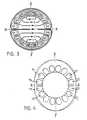
- the iron core of a known alternating current two-pole single phase induction motor is designed usually with the distribution of the equal magnetic yoke or is approximate shape as the base magnetism (as indicated in the attachments 1-2). Such an arrangement does not make the most economical use of the core. therefore, the known iron core does get the original point of polar axis. In other words, any position can be used as polar axis. Its defect, as indicated in Attachment 3 is that the known iron core causes irregular magnetic flux causing waste of iron core material. It is an object of the present invention to provide an improved distribution of the material of the core.
- the invention also includes an induction motor having a stator width gradually increasing iron core magnetic paths along polar axis' sides. This differs from the known stator design which has a varying original point of polar axis.
- the conventional alternating current single phase induction motor has side yoke of equal distance or similar equal distance with a design of indefinite polar axis position.
- Attachments 1-2 The above practical examples are all in the magnetic ways of the multi-wiring section type (as indicated in the Attachment 3) to produce irregular density to waste about 20% of the iron cores with the losses or resource, space and weight.
- the multi-wiring section type as indicated in the Attachment 3
- the design of this invention is to take "the distribution method and application of the gradually increasing iron core magnetic ways along the two sides of polar axis" to make the yoke width of iron core as the original point of the polar axis.
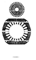
- the same pole is surrounded by wiring sections and the magnetic flux is generated in the gears (usually the magnetic flux is the width of tooth). It gradually increases the width of subsequent section as shown in Fig. 1 which is a practical example to gradually increase the width of yoke.
- the application principles are as follows:
- T1 is the first next tooth breadth on left or right side of T0
- T2 is the second next tooth breadth of T0 on left or right side
- T3 is the third next tooth breadth on the right or left side.
- TE is the most oustide tooth breadth on the left or right side under the magnetic pole.
- W0 is the yoke breadth between T0 and T1.
- W1 is the yoke breadth between T1 and T2.
- W2 is the yoke breadth between T2 and T3.
- WE is the yoke breadth adjacent to the magnetic pole.
- each tank and the yoke breadth of the outer edge indicate two widest breadth places with mechanical angle of 180 degrees.
- the two narrowest places link to form a line which is axis line X-X of magnetic axis line for the running wiring section.
- the axis line linked by the two widest places is the different magnetic poles boundary line Y-Y. these two axis lines cross to form an angle of 90 degrees.
- the yoke of magnetic path is the magnetic pole axis line for the running wiring section which develops toward two sides the demarcation boundary line of magnetic poles according to the gradual increasing quantity of magnetic flux of each tooth to enlarge the magnetic yoke into a gradual opening shape (or similar contour) that constitutes one of its features.
- Fig. 2 & 3 indicate the functional examples of such design.
- An alternative stator profile is shown by the chain lines.
- Fig. 3 is a practical example with its round fringe and gradual opening magnetic yoke.
- this design is made by means of yoke breadth which extends from the both sides of the polar axis of the single phase and dividing phase induction motor in accordance with the actual increasing volume of magnetic flux of each tooth for the same proportional increase of the widths without any decrease of its functions. It further reduces the cost of iron core's consumption and diminishes the weight and dimension of the motor. to the manufacture of the single phase motor, it gives great benefit to the user. Please examine our application in accordance with the regulations and laws of patent.
- T0 is the tooth breadth of the magnetic axis
- T1 is the first next neighboring tooth breadth on left or right side
- T2 is the second neighboring tooth breadth on the left and right sides of T0
- T3 is the third neighboring tooth breadth on the left and right sides of T0
- TE is the most outside tooth breadth on the left and right sides under the same magnetic pole.
- W0 is the yoke breadth between T0 and T1
- W1 is the yoke breadth between T1 and T2
- W2 is the yoke breadth between T2 and T3
- WE is the yoke breadth in the neighborhood of the magnetic poles
- the yoke thus formed according to the above design shall have the following features: -
- the top of the outer sides of each groove and the yoke breadth of the iron cores indicate that the two widest places have the mechanical angle difference of 180 degrees and that the two narrowest places also have the mechanical angle difference of 180 degrees.
- the two narrowest places are linked to form an axis line circling around the axis line of the magnetic pole X-X.
- the axis line formed by the two widest places is the different magnetic pole's boundary demarcation line Y-Y.
- the two axis lines cores into 90 degrees in angle.
- the yoke of the magnetic path is to circle around the polar axis of magnetic pole in the two sides toward the boundary line of adjoining magnetic poles.
- the magnetic yoke increases with the ever increasing quantity of magneticflux in each tooth to indicate an opening shape (or approximate contour) that is one of its features.
- the motor may have T0 - T e of unequal breadths according to the demand of the distribution of waveform with the principle of installing the yoke breadth of W0 -W e unchanged.
- the same tooth shapes and different groove forms with outer fringes to form a narrower yoke of the polar axis line of the running wiring section and wider yoke of the boundary line as an increasing ellipse or approximate contour based on the same principle.
- the different groove forms and different tooth shapes with outer fringes form the narrower yoke of the polar axis line of the running wiring section and wider yoke on the polar boundary line as an increasing ellipse or approximate contour based on the same principle.
- the different tooth shape and different groove forms with the various kinds of depths and the outer fringes in the shape of a round circle.
- a further feature is that the both narrower sides become parallel according to the gradually increasing yoke breadths in tangent with the sides of the formation of an approximate contour.
Landscapes
- Engineering & Computer Science (AREA)
- Power Engineering (AREA)
- Iron Core Of Rotating Electric Machines (AREA)
- Synchronous Machinery (AREA)
- Compressor (AREA)
- Reciprocating, Oscillating Or Vibrating Motors (AREA)
Priority Applications (1)
| Application Number | Priority Date | Filing Date | Title |
|---|---|---|---|
| AT88300380T ATE65649T1 (de) | 1987-01-16 | 1988-01-18 | Zweipoliger einphasen-induktionsmotor mit geblechtem kern. |
Applications Claiming Priority (2)
| Application Number | Priority Date | Filing Date | Title |
|---|---|---|---|
| GB08701037A GB2199995A (en) | 1987-01-16 | 1987-01-16 | The distribution method and application of the magnetic paths of the polar axis of the magnetic polar induction motor with multi-wirings for the single phase two-polar alternating current |
| GB8701037 | 1987-01-16 |
Publications (3)
| Publication Number | Publication Date |
|---|---|
| EP0283110A2 true EP0283110A2 (fr) | 1988-09-21 |
| EP0283110A3 EP0283110A3 (en) | 1988-11-23 |
| EP0283110B1 EP0283110B1 (fr) | 1991-07-24 |
Family
ID=10610835
Family Applications (1)
| Application Number | Title | Priority Date | Filing Date |
|---|---|---|---|
| EP88300380A Expired - Lifetime EP0283110B1 (fr) | 1987-01-16 | 1988-01-18 | Moteur monophasé à induction bipolaire ayant un noyau de fer feuilleté |
Country Status (5)
| Country | Link |
|---|---|
| EP (1) | EP0283110B1 (fr) |
| AT (1) | ATE65649T1 (fr) |
| DE (1) | DE3863800D1 (fr) |
| ES (1) | ES2023487B3 (fr) |
| GB (1) | GB2199995A (fr) |
Cited By (1)
| Publication number | Priority date | Publication date | Assignee | Title |
|---|---|---|---|---|
| WO2000062400A1 (fr) * | 1999-04-09 | 2000-10-19 | Motor Power Company S.R.L. | Moteur électrique synchrone sans balais |
Families Citing this family (3)
| Publication number | Priority date | Publication date | Assignee | Title |
|---|---|---|---|---|
| EP3035492B1 (fr) * | 2013-08-14 | 2023-03-15 | Geertsen, Bent | Enroulement de machine électrique à bobine centrale |
| CN103915962B (zh) * | 2014-03-28 | 2017-12-22 | 广东威灵电机制造有限公司 | 定子冲片和具有其的单相感应电机 |
| CN114520549B (zh) * | 2022-01-26 | 2025-11-28 | 珠海格力电器股份有限公司 | 一种自起动同步磁阻电机 |
Family Cites Families (8)
| Publication number | Priority date | Publication date | Assignee | Title |
|---|---|---|---|---|
| CH209221A (de) * | 1938-01-19 | 1940-03-31 | Tellert Fritz | Wechselstrommaschine. |
| GB887047A (en) * | 1958-11-18 | 1962-01-17 | Friedrich Tellert | Improvements in or relating to dynamo electric machines |
| US3235762A (en) * | 1962-05-02 | 1966-02-15 | Gen Electric | Stator for use in alternating current induction motors |
| GB986789A (en) * | 1964-01-25 | 1965-03-24 | Gen Electric | Multi-speed induction type motor |
| DE1563056C3 (de) * | 1966-06-13 | 1975-10-09 | Tellert, Fritz, 1000 Berlin | Ständerblech für eine vorzugsweise rippengekühlte Ein- oder Mehrphasenmaschine |
| US3942055A (en) * | 1974-10-16 | 1976-03-02 | General Electric Company | Hermetic motor stator |
| US4241274A (en) * | 1978-05-10 | 1980-12-23 | General Electric Company | Dynamoelectric machine and stationary assembly therefor |
| YU20386A (en) * | 1986-02-12 | 1988-04-30 | Iskra | Stator blades of single-phase asynchronic electric motors |
-
1987
- 1987-01-16 GB GB08701037A patent/GB2199995A/en not_active Withdrawn
-
1988
- 1988-01-18 ES ES88300380T patent/ES2023487B3/es not_active Expired - Lifetime
- 1988-01-18 AT AT88300380T patent/ATE65649T1/de not_active IP Right Cessation
- 1988-01-18 EP EP88300380A patent/EP0283110B1/fr not_active Expired - Lifetime
- 1988-01-18 DE DE8888300380T patent/DE3863800D1/de not_active Expired - Lifetime
Cited By (1)
| Publication number | Priority date | Publication date | Assignee | Title |
|---|---|---|---|---|
| WO2000062400A1 (fr) * | 1999-04-09 | 2000-10-19 | Motor Power Company S.R.L. | Moteur électrique synchrone sans balais |
Also Published As
| Publication number | Publication date |
|---|---|
| EP0283110B1 (fr) | 1991-07-24 |
| EP0283110A3 (en) | 1988-11-23 |
| GB2199995A (en) | 1988-07-20 |
| DE3863800D1 (de) | 1991-08-29 |
| ES2023487B3 (es) | 1992-01-16 |
| GB8701037D0 (en) | 1987-02-18 |
| ATE65649T1 (de) | 1991-08-15 |
Similar Documents
| Publication | Publication Date | Title |
|---|---|---|
| EP0647010B1 (fr) | Moteur électrique à aimants permanents à faible pulsation de couple | |
| DE19936361A1 (de) | Permanentmagnetmotor | |
| JPS6341307B2 (fr) | ||
| US2330824A (en) | Method of making magnetic cores | |
| ITTO940624A1 (it) | Rotore di macchina elettrica, in particolare di un motore elettrico per l'avviamento del motore a combustione interna di una autoveicolo e | |
| EP1459425B1 (fr) | Machine synchrone electrique a enroulement toroidal | |
| KR19990037453A (ko) | 영구자석 전동기 | |
| JPH0213539B2 (fr) | ||
| EP0283110A2 (fr) | Moteur monophasé à induction bipolaire ayant un noyau de fer feuilleté | |
| US4492890A (en) | Stator winding providing magnetomotive force wave of reduced harmonic content | |
| JP5179193B2 (ja) | 電動モータにおける高調波の減少 | |
| SE9704429D0 (sv) | Roterande elektrisk maskin | |
| Nee | Rotor slot design of inverter-fed induction motors | |
| US3652885A (en) | Synchronous reluctance motor | |
| KR920000685B1 (ko) | 동기 전동기 | |
| JP3719569B2 (ja) | 内磁形モータのロータ構造 | |
| JPH08182238A (ja) | ステータ | |
| JPS6039352A (ja) | 小形コンデンサ誘導電動機用コア | |
| US4518942A (en) | Electric machine, such as transformer choke, constant-voltage regulator or the like | |
| US2047831A (en) | Induction motor | |
| JP3214508B2 (ja) | 車両用交流発電機 | |
| JPS62217843A (ja) | 単相非同期電動機のステ−タ成層体 | |
| JPH03159531A (ja) | レラクタンス回転機 | |
| US2796543A (en) | Polyphase induction-type motors | |
| US2407625A (en) | Magnetic core |
Legal Events
| Date | Code | Title | Description |
|---|---|---|---|
| PUAI | Public reference made under article 153(3) epc to a published international application that has entered the european phase |
Free format text: ORIGINAL CODE: 0009012 |
|
| AK | Designated contracting states |
Kind code of ref document: A2 Designated state(s): AT BE CH DE ES FR GB GR IT LI LU NL SE |
|
| PUAL | Search report despatched |
Free format text: ORIGINAL CODE: 0009013 |
|
| AK | Designated contracting states |
Kind code of ref document: A3 Designated state(s): AT BE CH DE ES FR GB GR IT LI LU NL SE |
|
| 17P | Request for examination filed |
Effective date: 19890522 |
|
| 17Q | First examination report despatched |
Effective date: 19890926 |
|
| GRAA | (expected) grant |
Free format text: ORIGINAL CODE: 0009210 |
|
| AK | Designated contracting states |
Kind code of ref document: B1 Designated state(s): AT BE CH DE ES FR GB GR IT LI LU NL SE |
|
| PG25 | Lapsed in a contracting state [announced via postgrant information from national office to epo] |
Ref country code: SE Effective date: 19910724 Ref country code: NL Effective date: 19910724 Ref country code: LI Effective date: 19910724 Ref country code: GR Free format text: LAPSE BECAUSE OF FAILURE TO SUBMIT A TRANSLATION OF THE DESCRIPTION OR TO PAY THE FEE WITHIN THE PRESCRIBED TIME-LIMIT Effective date: 19910724 Ref country code: CH Effective date: 19910724 Ref country code: BE Effective date: 19910724 Ref country code: AT Effective date: 19910724 |
|
| REF | Corresponds to: |
Ref document number: 65649 Country of ref document: AT Date of ref document: 19910815 Kind code of ref document: T |
|
| REF | Corresponds to: |
Ref document number: 3863800 Country of ref document: DE Date of ref document: 19910829 |
|
| ITF | It: translation for a ep patent filed | ||
| REG | Reference to a national code |
Ref country code: CH Ref legal event code: PL |
|
| ET | Fr: translation filed | ||
| NLV1 | Nl: lapsed or annulled due to failure to fulfill the requirements of art. 29p and 29m of the patents act | ||
| PLBI | Opposition filed |
Free format text: ORIGINAL CODE: 0009260 |
|
| REG | Reference to a national code |
Ref country code: ES Ref legal event code: FG2A Ref document number: 2023487 Country of ref document: ES Kind code of ref document: B3 |
|
| PG25 | Lapsed in a contracting state [announced via postgrant information from national office to epo] |
Ref country code: LU Free format text: LAPSE BECAUSE OF NON-PAYMENT OF DUE FEES Effective date: 19920131 |
|
| 26 | Opposition filed |
Opponent name: SIEMENS AKTIENGESELLSCHAFT, BERLIN UND MUENCHEN Effective date: 19911219 |
|
| APAC | Appeal dossier modified |
Free format text: ORIGINAL CODE: EPIDOS NOAPO |
|
| PLBN | Opposition rejected |
Free format text: ORIGINAL CODE: 0009273 |
|
| STAA | Information on the status of an ep patent application or granted ep patent |
Free format text: STATUS: OPPOSITION REJECTED |
|
| 27O | Opposition rejected |
Effective date: 19960716 |
|
| PGFP | Annual fee paid to national office [announced via postgrant information from national office to epo] |
Ref country code: GB Payment date: 19970113 Year of fee payment: 10 |
|
| PGFP | Annual fee paid to national office [announced via postgrant information from national office to epo] |
Ref country code: FR Payment date: 19970131 Year of fee payment: 10 Ref country code: ES Payment date: 19970131 Year of fee payment: 10 |
|
| PGFP | Annual fee paid to national office [announced via postgrant information from national office to epo] |
Ref country code: DE Payment date: 19970327 Year of fee payment: 10 |
|
| PG25 | Lapsed in a contracting state [announced via postgrant information from national office to epo] |
Ref country code: GB Free format text: LAPSE BECAUSE OF NON-PAYMENT OF DUE FEES Effective date: 19980118 |
|
| PG25 | Lapsed in a contracting state [announced via postgrant information from national office to epo] |
Ref country code: ES Free format text: LAPSE BECAUSE OF NON-PAYMENT OF DUE FEES Effective date: 19980119 |
|
| PG25 | Lapsed in a contracting state [announced via postgrant information from national office to epo] |
Ref country code: FR Free format text: THE PATENT HAS BEEN ANNULLED BY A DECISION OF A NATIONAL AUTHORITY Effective date: 19980131 |
|
| GBPC | Gb: european patent ceased through non-payment of renewal fee |
Effective date: 19980118 |
|
| PG25 | Lapsed in a contracting state [announced via postgrant information from national office to epo] |
Ref country code: DE Free format text: LAPSE BECAUSE OF NON-PAYMENT OF DUE FEES Effective date: 19981001 |
|
| REG | Reference to a national code |
Ref country code: FR Ref legal event code: ST |
|
| REG | Reference to a national code |
Ref country code: ES Ref legal event code: FD2A Effective date: 20000403 |
|
| PG25 | Lapsed in a contracting state [announced via postgrant information from national office to epo] |
Ref country code: IT Free format text: LAPSE BECAUSE OF NON-PAYMENT OF DUE FEES;WARNING: LAPSES OF ITALIAN PATENTS WITH EFFECTIVE DATE BEFORE 2007 MAY HAVE OCCURRED AT ANY TIME BEFORE 2007. THE CORRECT EFFECTIVE DATE MAY BE DIFFERENT FROM THE ONE RECORDED. Effective date: 20050118 |
|
| APAH | Appeal reference modified |
Free format text: ORIGINAL CODE: EPIDOSCREFNO |