EP0283360A1 - Kryostat zur Kennzeichnung von Körpern unter veränderlicher Temperatur und mit schwacher Streustrahlung - Google Patents
Kryostat zur Kennzeichnung von Körpern unter veränderlicher Temperatur und mit schwacher Streustrahlung Download PDFInfo
- Publication number
- EP0283360A1 EP0283360A1 EP88400427A EP88400427A EP0283360A1 EP 0283360 A1 EP0283360 A1 EP 0283360A1 EP 88400427 A EP88400427 A EP 88400427A EP 88400427 A EP88400427 A EP 88400427A EP 0283360 A1 EP0283360 A1 EP 0283360A1
- Authority
- EP
- European Patent Office
- Prior art keywords
- cryostat according
- cryostat
- sample
- conduit
- support
- Prior art date
- Legal status (The legal status is an assumption and is not a legal conclusion. Google has not performed a legal analysis and makes no representation as to the accuracy of the status listed.)
- Ceased
Links
- 230000005855 radiation Effects 0.000 title claims abstract description 15
- 239000012530 fluid Substances 0.000 claims abstract description 27
- 239000011248 coating agent Substances 0.000 claims abstract description 12
- 238000000576 coating method Methods 0.000 claims abstract description 12
- 230000002745 absorbent Effects 0.000 claims abstract description 8
- 239000002250 absorbent Substances 0.000 claims abstract description 8
- 230000003071 parasitic effect Effects 0.000 claims description 9
- 238000012512 characterization method Methods 0.000 claims description 6
- 239000007788 liquid Substances 0.000 claims description 6
- 230000003287 optical effect Effects 0.000 claims description 5
- 230000000087 stabilizing effect Effects 0.000 claims description 5
- OKTJSMMVPCPJKN-UHFFFAOYSA-N Carbon Chemical compound [C] OKTJSMMVPCPJKN-UHFFFAOYSA-N 0.000 claims description 4
- 239000011230 binding agent Substances 0.000 claims description 2
- 229910052799 carbon Inorganic materials 0.000 claims description 2
- 239000004020 conductor Substances 0.000 claims description 2
- 238000005485 electric heating Methods 0.000 claims 1
- 238000001816 cooling Methods 0.000 abstract description 2
- 230000003019 stabilising effect Effects 0.000 abstract 1
- 238000010438 heat treatment Methods 0.000 description 6
- 230000004907 flux Effects 0.000 description 4
- 238000005259 measurement Methods 0.000 description 4
- 238000004804 winding Methods 0.000 description 4
- 239000012071 phase Substances 0.000 description 3
- 239000004744 fabric Substances 0.000 description 2
- 239000007789 gas Substances 0.000 description 2
- 229910052738 indium Inorganic materials 0.000 description 2
- APFVFJFRJDLVQX-UHFFFAOYSA-N indium atom Chemical compound [In] APFVFJFRJDLVQX-UHFFFAOYSA-N 0.000 description 2
- RYGMFSIKBFXOCR-UHFFFAOYSA-N Copper Chemical group [Cu] RYGMFSIKBFXOCR-UHFFFAOYSA-N 0.000 description 1
- 238000010521 absorption reaction Methods 0.000 description 1
- 239000000853 adhesive Substances 0.000 description 1
- 230000001070 adhesive effect Effects 0.000 description 1
- 230000000712 assembly Effects 0.000 description 1
- 238000000429 assembly Methods 0.000 description 1
- 230000000295 complement effect Effects 0.000 description 1
- 238000010276 construction Methods 0.000 description 1
- 238000007872 degassing Methods 0.000 description 1
- 238000007599 discharging Methods 0.000 description 1
- 239000001307 helium Substances 0.000 description 1
- 229910052734 helium Inorganic materials 0.000 description 1
- SWQJXJOGLNCZEY-UHFFFAOYSA-N helium atom Chemical compound [He] SWQJXJOGLNCZEY-UHFFFAOYSA-N 0.000 description 1
- 238000009434 installation Methods 0.000 description 1
- 238000009413 insulation Methods 0.000 description 1
- 239000012212 insulator Substances 0.000 description 1
- 239000007791 liquid phase Substances 0.000 description 1
- 229910052751 metal Inorganic materials 0.000 description 1
- 239000002184 metal Substances 0.000 description 1
- 201000009240 nasopharyngitis Diseases 0.000 description 1
- 238000013021 overheating Methods 0.000 description 1
- 239000000843 powder Substances 0.000 description 1
- 238000005086 pumping Methods 0.000 description 1
- 230000001105 regulatory effect Effects 0.000 description 1
- 238000007789 sealing Methods 0.000 description 1
- 238000000926 separation method Methods 0.000 description 1
- 239000000725 suspension Substances 0.000 description 1
- 239000002470 thermal conductor Substances 0.000 description 1
Images

Classifications
-
- F—MECHANICAL ENGINEERING; LIGHTING; HEATING; WEAPONS; BLASTING
- F17—STORING OR DISTRIBUTING GASES OR LIQUIDS
- F17C—VESSELS FOR CONTAINING OR STORING COMPRESSED, LIQUEFIED OR SOLIDIFIED GASES; FIXED-CAPACITY GAS-HOLDERS; FILLING VESSELS WITH, OR DISCHARGING FROM VESSELS, COMPRESSED, LIQUEFIED, OR SOLIDIFIED GASES
- F17C3/00—Vessels not under pressure
- F17C3/02—Vessels not under pressure with provision for thermal insulation
- F17C3/08—Vessels not under pressure with provision for thermal insulation by vacuum spaces, e.g. Dewar flask
- F17C3/085—Cryostats
Definitions
- the present invention relates to a cryostat for the characterization, at variable temperature, of bodies under weak parasitic fluxes.
- a possible but not exclusive application concerns sensors or emitters of infrared radiation.
- cryostats developed so far are not well suited for such uses. Their temperature stability is insufficient and they do not make it possible to establish a sufficiently dark medium for the radiation that one does not wish to capture. In addition, they take a long time to put into service and require a fairly large flow of cryogenic fluid.
- the invention overcomes this double drawback: its object is a cryostat provided with means for stabilizing and adjusting the temperature to which the sample is brought, as well as means capable of reducing, by absorbing them, the parasitic fluxes which come disrupt measurements coming either from known and calibrated emissive sources, or from the environment.
- the invention relates to a cryostat for the characterization of the electro-optical or optical properties of samples, in particular sensors or emitters of low intensity radiation, comprising a vacuum chamber containing a support on which the sample is fixed. characterize, a fluid circuit formed by a conduit for transporting a cryogenic fluid to the support and a conduit for discharging the cryogenic fluid outside the enclosure, characterized in that it comprises means for adjusting and stabilizing the temperature of the sample as well as means for absorbing parasitic radiation affecting the characterization of the sample.
- the means for regulating and stabilizing the temperature of the sample firstly include an arrangement of the evacuation duct in annular section and surrounding the conveying duct. These conduits are separated by a space in which a vacuum is created.
- a tube surrounds the evacuation duct with a clearance in which the vacuum is also produced.
- the cryogenic fluid in the conveying conduit is liquid before arriving against the resistance and then vaporizes, and a filter made of thermal conductive material is placed at this point in the conveying conduit so as to homogenize the temperature of the fluid, and separating the liquid phase from the gas phase.
- the electric wires connecting, if necessary, the support to an apparatus located outside the enclosure are preferably in contact with one or more sources at constant temperature in the enclosure to absorb heat losses.
- the means suitable for reducing parasitic fluxes comprise, for their part, an envelope surrounding the support, the outer surface of which is provided with a reflective coating and the inner surface provided with an absorbent coating. Likewise, the parts of the cryostat located inside the envelope are covered with an absorbent coating.
- the absorbent coating is advantageously composed of carbon grains of 85 microns or less in diameter, agglomerated by a binder.
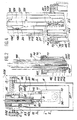
- FIG. 1 shows the cryostat as a whole. It consists of a vacuum enclosure 1, the content of which will be described in more detail below, of a bottle of cryogenic fluid such as liquid helium and of a fluid circuit 101 connecting the bottle 100 to the enclosure 1.
- the fluid circuit 101 comprises a conduit 109 for the cryogenic fluid from the bottle 100 to the enclosure 1 and a conduit 112 for evacuating the cryogenic fluid from the enclosure 1.
- the circulation of the cryogenic fluid is ensured by a pump 102.
- a filter 103 at the inlet of the routing conduit 109 makes it possible to retain the suspensions of the cryogenic liquid.
- the vacuum enclosure 1 is made up of two parts: a box 2 provided with a vacuum outlet 55, and a cover 3.
- Figure 2 shows in detail the contents of the enclosure 1: an intermediate flange 5 placed on a shoulder 6 of the box 2 unites it to the cover 3 using bolts 7. Two circular joints 93 and 94 ensuring l seals are installed on either side of the intermediate box 5.
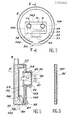
- the box 2 is optionally provided with a transparent window 30 (shown in FIG. 3) if it is planned to carry out optical measurements on the sample.
- the cover 3 includes a sleeve 46 for holding the fluid circuit 101 in place as well as a screen support 86 which is placed inside the enclosure 1.
- the cylindrical sleeve consists of two concentric walls: an internal wall 206 which is connected to the screen support 86 at its lower end, and an external wall 207 which is connected to a flat part 208, sealing the box 2, of the cover 3.
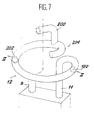
- a U-shaped tube 10 is located inside the vacuum enclosure 1; its two arms 8 and 11 are fixed on the screen support 86 and open out inside the sleeve 46, the second via an exchanger tube 12 which borders the internal surface of the screen support 86 and is wound on the periphery thereof, then a branch 200 which passes through the screen support 86 and the internal wall 206 of the sleeve 46.
- the U-shaped tube 10 also maintains a cold head 4, sample support to characterize and which will be described later.
- a screen 31 almost completely surrounds this cold head 4 as can also be seen in FIG. 3; it is held in place by a contact surface 87 on the screen support 86; its internal surface 33, oriented towards the cold head 4, comprises an absorbent coating 146, and its external surface 32 is reflective.
- the fluid circuit 101 is concretely produced by means of two rods each formed from two concentric tubes connected at their ends.
- the internal rod 113 is located in the inner tube of the external rod 110; it is centered approximately by engagement in a recess 123 of the screen support 86.
- the external rod 110 is centered with a small clearance by engagement in the sleeve 46. It is provided with a shoulder 14 which comes into contact with a flange 13 to which the two walls 206 and 207 of the sleeve 46 are connected at their upper end; a clamp 15 maintains this contact by means of a thread 16 complementary to a thread of the rim 13.
- a seal 128 is interposed between the rim 13 and the shoulder 14.
- the exhaust duct 112 is formed in the interval between the two rods 110 and 113 and produced by means of the two centering operations mentioned above; the routing conduit 109 is formed in the inner tube of the inner rod 113. As a result, an interval 114 in which a vacuum is produced separates the two conduits; and another interval 111 in which the vacuum is produced separates the two tubes from the external rod 110, around the evacuation duct 112.
- the branch 11 of the U-shaped tube 10 opens into the exchanger tube 12 which is wound on the periphery of the internal surface of the screen support 86. It is cut by the section plane of Figure 2, along two sections 120 and 202; the part of the exchanger tube 12 which connects these two sections passes in front of the cutting plane and is therefore not shown here.
- the exchanger tube 12 is then wound around the recess 123 and ends at one end 204 which carries the branch 200.
- centralizers 25 are introduced in the empty interval 114. They consist of a curved elastic strip 124 whose ends bear supports 125 oriented towards the concavity of the strip 124 and whose middle carries a support 126 oriented towards its convexity. The supports 125 are in contact with the internal tube of the internal rod 113, the supports 126 with its external tube. Trios of lamellae 124 arranged at different angles allow good centering of the two tubes of the internal rod 113. The heat losses due to the centralizers 25, rendered as insulating as possible, are very weak.
- the cryogenic fluid originating from the bottle 100 and circulating in the conveying conduit 109 undergoes heating before entering the branch 8 of the U-shaped tube 10.
- a heating resistor formed is used a coil 23 around a copper part 127 of the internal tube of the internal rod 113.
- the coil 23 is disposed between electrical wires 21 and 22 connected to the outside of the installation and which pass inside a connection 24 which passes through the external tube of the internal rod 113 and the external rod 110; the winding of the winding is such that the magnetic fields it induces are nonexistent.
- a metallic fabric 20 wound on itself is introduced into the routing conduit 109 opposite the winding 23. It serves both as a thermal conductor and as a phase separator. We will return to this point later.
- the cold head 4 has a hollow in which an indium sheet 34 is deposited, then a support 35 for a sample 36 whose characteristics must be determined.
- the cold head 4 can accommodate various screens 38 or 96 (the latter constituting FIG. 6) using bolt assemblies 95 depending on the properties of the sample 36.
- the screen 38 or 96 is separated from the head cold by a radiation-tight seal 37, electrically insulating in the part 81, and in which are made passages for the electrical connections 80 connecting electrical contacts on the support 35 to the outside environment.
- the connections 80 are formed by what is called a "dab": a double flat insulator enveloping several conductive wires.
- the ends 81 of the wires are stripped before entering the joint 37, which limits the radiation transfers.
- the screen 96 completely closing the volume in which the sample 36 is located can be used when the measurements to be carried out are in total darkness. But we can also perform optical measurements, and it is then a screen 38 provided with an opening opposite the sample 36 that must be used.
- the screen can be closed by a cover 39 with a transparent passage 40 which defines an opening angle F of the beam 41 which can be observed after it has passed through the optical window 30 on the box 2, as shown Figure 3. It is obviously mandatory that the screen 31 is interrupted on the way to the beam 41.
- the screen 38 has a hollow cylindrical part 129 surrounding the beam 41 and provided with circumferential grooves of triangular section on its internal surface 42 so as to absorb the parasitic radiation having reached the face 42 which could be reflected, which would disturb the beam F of the signal received by 36.
- the requirement to absorb parasitic radiation and to work in as complete darkness as possible leads to covering the surfaces located inside the screen 31 with a suitable coating and in particular, in addition to the internal surface 33 of this screen 31: the external surfaces 145 and 144 of the branches 8 and 11 of the U-shaped tube 10, the surface 143 of the insulation of the electrical connections 80, the surfaces 142 or 141 of the screens 38 or 96 as well as the surfaces 140 of the cold head 4.
- the surfaces located inside the casing 31 are covered with this coating.
- a powder consisting of grains of activated carbon with a diameter of about 85 microns, smaller grains which may also be suitable, and which is agglomerated by means of an adhesive suitable for low temperatures.
- the assembly has very good absorption properties, especially for infrared, and resistance to vacuum without degassing.
- the cryogenic fluid passes from the bottle 100 to the vacuum enclosure 1 through the conveying conduit 109. It remains liquid until it has reached the coil 23 and is vaporized by the heat emitted by the latter.
- the intensity of the current flowing through the winding 23 determines the extent of the overheating and therefore the temperature of the cryogenic vapor at the moment when it enters the branch 8 of the U-shaped tube.
- the metal fabric 20 ensures a good distribution of the heating between all parts of the fluid and helps to separate the liquid and gas phases by capillarity.
- the temperature of the cold head 4 and of the sample 36 is therefore, after a start-up period of the cryostat, that of the vapor which circulates in the U-shaped tube 10.
- the steam After leaving the branch 11 of the U-shaped tube 10 and the distribution circuit 12, the steam enters the exhaust duct 112 which is surrounded by the gap 111 in which the vacuum has been created and which isolates it from the medium outside.
- the heating of the vapor is therefore limited during its journey in the vacuum enclosure 1 towards the pump 102.
- the other interval 114 in which the vacuum has been created separates the evacuation conduits 112 and d routing 109, it can be concluded that the heating of the cryogenic fluid during its journey between the bottle 100 and the vacuum enclosure 1 is also very reduced.
- connections 80 are brought into contact with points of constant temperature and less and less cold when we s moves away from the support 35 of the sample 36.
- these points are three in number.
- a first point 88 establishes contact between the connections 80 and the cold head 4 and therefore maintains the connections 80 at a temperature very close to that of the sample 36;
- a second point 89 establishes contact between the connections 80 and the branch 11 of the U-shaped tube 10, optionally by a thermal conductive connection 85;
- a third point 90 establishes contact between the connections 80 and the screen support 86.
- the cryostat according to the invention therefore has the double advantage of providing very good temperature stability prevailing in the vacuum chamber, as well as roughly total observation conditions in darkness which make it especially interesting for samples 36 to be characterized under low flux.
- its thermal losses are very limited and it can be built with a very small size, which gives it a low thermal inertia also.
Landscapes
- Engineering & Computer Science (AREA)
- Physics & Mathematics (AREA)
- Thermal Sciences (AREA)
- Mechanical Engineering (AREA)
- General Engineering & Computer Science (AREA)
- Investigating Or Analysing Materials By Optical Means (AREA)
Applications Claiming Priority (2)
| Application Number | Priority Date | Filing Date | Title |
|---|---|---|---|
| FR8702688 | 1987-02-27 | ||
| FR8702688A FR2611869B1 (fr) | 1987-02-27 | 1987-02-27 | Cryostat pour la caracterisation a temperature variable de corps sous faibles flux parasites |
Publications (1)
| Publication Number | Publication Date |
|---|---|
| EP0283360A1 true EP0283360A1 (de) | 1988-09-21 |
Family
ID=9348437
Family Applications (1)
| Application Number | Title | Priority Date | Filing Date |
|---|---|---|---|
| EP88400427A Ceased EP0283360A1 (de) | 1987-02-27 | 1988-02-24 | Kryostat zur Kennzeichnung von Körpern unter veränderlicher Temperatur und mit schwacher Streustrahlung |
Country Status (2)
| Country | Link |
|---|---|
| EP (1) | EP0283360A1 (de) |
| FR (1) | FR2611869B1 (de) |
Citations (2)
| Publication number | Priority date | Publication date | Assignee | Title |
|---|---|---|---|---|
| US3250684A (en) * | 1959-12-15 | 1966-05-10 | Commissariat Energie Atomique | Cryogenic apparatus for irradiation at low temperatures |
| US3306075A (en) * | 1965-10-04 | 1967-02-28 | Hughes Aircraft Co | Thermal coupling structure for cryogenic refrigeration |
-
1987
- 1987-02-27 FR FR8702688A patent/FR2611869B1/fr not_active Expired
-
1988
- 1988-02-24 EP EP88400427A patent/EP0283360A1/de not_active Ceased
Patent Citations (2)
| Publication number | Priority date | Publication date | Assignee | Title |
|---|---|---|---|---|
| US3250684A (en) * | 1959-12-15 | 1966-05-10 | Commissariat Energie Atomique | Cryogenic apparatus for irradiation at low temperatures |
| US3306075A (en) * | 1965-10-04 | 1967-02-28 | Hughes Aircraft Co | Thermal coupling structure for cryogenic refrigeration |
Non-Patent Citations (4)
| Title |
|---|
| INSTRUMENTS AND EXPERIMENTAL TECHNIQUES, vol. 28, no. 5, partie 2, septembre/octobre 1985, pages 1218-1220, Plenum Publishing Corp., New York, US; A.S. BULATOV et al.: "Circulating cryostat for diffractometer for structure research at temperatures of 4.2-300degreeK" * |
| JOURNAL OF PHYSICS E: SCIENTIFIC INSTRUMENTS, vol. 11, 1978, pages 801-804, The Institute of Physics, Londres, GB; E. KRAUSZ et al.: "A top-loading matrix isolation apparatus for magneto-optical investigations" * |
| JOURNAL OF SCIENTIFIC INSTRUMENTS, (JOURNAL OF PHYSICS E), vol. 1, no. 1, series 2, janvier 1968, pages 15-21, Londres, GB; R.R. BIRSS et al.: "A cryostat for use with a torque magnetometer down to 4.2degreeK" * |
| PROCEEDINGS OF THE SIXTH INTERNATIONAL CRYOGENIC ENGINEERING CONFERENCE, Grenoble, 11-14 mai 1976, pages 157-158, IPC Science and Technology Press, Londres, GB; G. DAVEY: "The design of small constant flow cryostats" * |
Also Published As
| Publication number | Publication date |
|---|---|
| FR2611869B1 (fr) | 1989-06-09 |
| FR2611869A1 (fr) | 1988-09-09 |
Similar Documents
| Publication | Publication Date | Title |
|---|---|---|
| EP0346170B1 (de) | Vorrichtung zum Messen von Parametern in der Spaltzone eines im Betrieb befindlichen Kernreaktors | |
| EP2110887B1 (de) | Verbindungsanordnung von zwei Supraleitungskabeln | |
| FR2560421A1 (fr) | Dispositif de refroidissement de bobinages supraconducteurs | |
| FR2570174A1 (fr) | Recipient a eprouvettes stabilise par un caloduc | |
| FR2700657A1 (fr) | Ensemble radiogène. | |
| EP1703611A1 (de) | Elektrische Durchführung für supraleitendes Element | |
| CH618785A5 (de) | ||
| EP0231747B1 (de) | Stator mit supraleitenden Dreiphasenwicklungen | |
| EP0369913A1 (de) | Vorrichtung zum Tansferieren und zum unter kontrollierter Atmosphäre in-situ-Reagieren von zu untersuchenden Proben mittels Transmissions-Elektronenmikroskopie | |
| EP0283360A1 (de) | Kryostat zur Kennzeichnung von Körpern unter veränderlicher Temperatur und mit schwacher Streustrahlung | |
| EP2038978B1 (de) | Elektrische durchführungsstruktur für ein supraleitendes element | |
| FR2713405A1 (fr) | Module d'amenée de courant pour l'alimentation d'une charge électrique supraconductrice à basse température critique. | |
| FR2748848A1 (fr) | Enveloppe pour source de rayonnement electromagnetique et procede pour l'elimination du rayonnement electromagnetique extrafocal | |
| CA2055809C (fr) | Procede de refroidissement d'une amenee de courant pour appareillage electrique a tres basse temperature et dispositif pour sa mise en oeuvre | |
| EP0004220A1 (de) | Sonnenenergiekollektor | |
| FR2593649A1 (fr) | Laser a gaz scelle. | |
| EP1715314B1 (de) | Vorrichtung zur Detektion von Infrarotstrahlung, Lenksystem ausgestattet mit dieser Vorrichtung und selbstgesteuertes Geschoss ausgestattet mit diesem Lenksystem. | |
| EP0220086B1 (de) | Flüssiggasüberführungsrohr mit thermischem Schirm und mit einem Wärmetauscher versehen | |
| EP0155201B1 (de) | Abkühlungsvorrichtung für Gefrierstopfbüchse einer Ventilbetätigungsspindel | |
| FR2623043A1 (fr) | Dispositif de chauffage a resistance electrique isole | |
| FR2637728A1 (fr) | Amenee de courant cryogenique a faibles pertes | |
| FR2587797A1 (fr) | Dispositif de retenue pour un getter amorce electriquement, gyroscope a laser contenant un tel dispositif et procede de retenue d'un getter dans un tel gyroscope a laser | |
| FR2985855A1 (fr) | Procede pour la realisation de traversees electriques etanches au travers d'un boitier d'encapsulation et boitier d'encapsulation muni d'au moins l'une de ces traversees electriques | |
| FR2925760A1 (fr) | Refroidissement d'un tube generateur de rayons x | |
| FR2749651A1 (fr) | Dispositif de protection pour un appareil d'inspection ou de controle utilise dans un milieu a haute temperature et son utilisation |
Legal Events
| Date | Code | Title | Description |
|---|---|---|---|
| PUAI | Public reference made under article 153(3) epc to a published international application that has entered the european phase |
Free format text: ORIGINAL CODE: 0009012 |
|
| AK | Designated contracting states |
Kind code of ref document: A1 Designated state(s): DE GB IT |
|
| 17P | Request for examination filed |
Effective date: 19890222 |
|
| 17Q | First examination report despatched |
Effective date: 19891204 |
|
| STAA | Information on the status of an ep patent application or granted ep patent |
Free format text: STATUS: THE APPLICATION HAS BEEN REFUSED |
|
| 18R | Application refused |
Effective date: 19910318 |