EP0283403A1 - Handhabungsgerät zum Bestücken einer Werkzeugmaschine - Google Patents
Handhabungsgerät zum Bestücken einer Werkzeugmaschine Download PDFInfo
- Publication number
- EP0283403A1 EP0283403A1 EP88400654A EP88400654A EP0283403A1 EP 0283403 A1 EP0283403 A1 EP 0283403A1 EP 88400654 A EP88400654 A EP 88400654A EP 88400654 A EP88400654 A EP 88400654A EP 0283403 A1 EP0283403 A1 EP 0283403A1
- Authority
- EP
- European Patent Office
- Prior art keywords
- axis
- manipulator
- wrist
- machine tool
- along
- Prior art date
- Legal status (The legal status is an assumption and is not a legal conclusion. Google has not performed a legal analysis and makes no representation as to the accuracy of the status listed.)
- Withdrawn
Links
Images

Classifications
-
- B—PERFORMING OPERATIONS; TRANSPORTING
- B25—HAND TOOLS; PORTABLE POWER-DRIVEN TOOLS; MANIPULATORS
- B25J—MANIPULATORS; CHAMBERS PROVIDED WITH MANIPULATION DEVICES
- B25J15/00—Gripping heads and other end effectors
- B25J15/0052—Gripping heads and other end effectors multiple gripper units or multiple end effectors
-
- B—PERFORMING OPERATIONS; TRANSPORTING
- B23—MACHINE TOOLS; METAL-WORKING NOT OTHERWISE PROVIDED FOR
- B23Q—DETAILS, COMPONENTS, OR ACCESSORIES FOR MACHINE TOOLS, e.g. ARRANGEMENTS FOR COPYING OR CONTROLLING; MACHINE TOOLS IN GENERAL CHARACTERISED BY THE CONSTRUCTION OF PARTICULAR DETAILS OR COMPONENTS; COMBINATIONS OR ASSOCIATIONS OF METAL-WORKING MACHINES, NOT DIRECTED TO A PARTICULAR RESULT
- B23Q7/00—Arrangements for handling work specially combined with or arranged in, or specially adapted for use in connection with, machine tools, e.g. for conveying, loading, positioning, discharging, sorting
- B23Q7/04—Arrangements for handling work specially combined with or arranged in, or specially adapted for use in connection with, machine tools, e.g. for conveying, loading, positioning, discharging, sorting by means of grippers
-
- B—PERFORMING OPERATIONS; TRANSPORTING
- B25—HAND TOOLS; PORTABLE POWER-DRIVEN TOOLS; MANIPULATORS
- B25J—MANIPULATORS; CHAMBERS PROVIDED WITH MANIPULATION DEVICES
- B25J9/00—Program-controlled manipulators
- B25J9/02—Program-controlled manipulators characterised by movement of the arms, e.g. cartesian coordinate type
- B25J9/023—Cartesian coordinate type
Definitions
- the present invention relates to automated machines controlled by computers ensuring the loading and unloading of parts machined by a machine tool.
- Automaton manipulators also known as robots known to date for carrying out loading operations, that is to say positioning with precision a workpiece taken from a feed station in the automatic chuck of the machine -tool, and the unloading of the part after machining by removing it from the mandrel to deposit it at a discharge station, have many drawbacks.
- the so-called compor articulated arm robots attempt the trajectories of the moving parts of the robot which occupy a large and variable volumetric space according to the part to be handled and according to the machine served.
- manipulators are in principle suitable for serving a well-defined type of machine and they cannot be changed from the workstation, especially since, for robots of the articulated arm type, the center of gravity of the robot can move within wide limits, which requires a solid ground anchoring of the foot or base of the robot.
- the machines known for this purpose are generally slow because the spatial displacements of the various elements of the manipulator are executed successively by breaking down the movement and that the two operations of unloading and loading of the part must succeed one another over time for a period machine tool stop.
- the robot manipulator which is not specific to a defined machine tool being incorporated between a supply assembly for the workpieces and evacuation of the workpieces not specific to the robot and said machine, the positioning of the pieces on the conveyor belt or the supply pallets most often have an imprecision which is detrimental to the entry of the workpieces and the workpieces must most often be stored manually after having been deposited in a more or less random manner on a tray. reception.
- the object of the present invention is to remedy these various drawbacks and to create a manipulator automaton controlled by a programmable computer which is of compact structure, which can be combined with adaptation to substantially all types of machine tools while taking up the environment as little as possible. of the latter and which incorporates its own system of supply and evacuation of parts to ensure high positioning accuracy. It also aims to increase the efficiency of the machine tool by limiting the duration of its stoppage to opera removal and positioning of the part on the machine, the approach and evacuation phases of the part being carried out during the machining phase and the elementary displacements of the elements of the structure being effected simultaneously at the maximum the speed of the drive means of each element.
- the invention therefore relates to a manipulator automaton for loading and unloading the workpieces on a machine tool, which comprises a base supporting a manipulator of the type comprising a chain of elements whose movement is broken down along three axes orthogonal, the wrist carrying the handling grippers being mounted on the chain element located opposite the base and this wrist having at least one possibility of rotation about an axis, characterized in that the axis perpendicular according to which the movement of approach and distance of the manipulated part from the machine is carried out is located at a level higher than that of the level of circulation in the phases of supply and evacuation of the parts to be machined and perpendicular both to the direction of circulation of the parts during these phases and to the axis of the spindle of the machine tool, the second horizontal axis being perpendicular to the first and movable along the latter and the third axis being the vertical axis perpendicular to the second horizontal axis and movable along the latter and the poitnet being constituted by a shaft parallel to
- the wrist carries at its end two gripping elements whose gripping axes are orthogonal.
- the two gripping elements can be constituted by two pliers, the jaws constituting the two pliers being movable in two perpendicular planes eccentric relative to the axis of the shaft constituting the wrist.
- the parts are supplied on a tray positioned manually or automatically in a supply station, said tray being supported at this station by a carriage provided with a centering and lifting and lowering device.
- tray this carriage being movable in a controlled manner in the direction of circulation to present the tray in a precise defined position with respect to the three axes of the manipulator.
- the device for supplying the workpieces and for evacuating the machined parts could, however, be of another type, particularly when the supply and evacuation are ensured according to the so-called "bulk" system.
- the pieces can be brought by a conveyor belt or the like provided with a device for precise positioning of the pieces at the point of engagement by the manipulating wrist, the evacuation being ensured by a conveyor belt or the like with parallel transport direction. to that of the conveyor belt.
- the manipulator after positioning in front of a machine tool can be reprogrammed by taking, as zero reference, one of the pliers brought into coincidence with the axis of the chuck of the machine.
- Any movement of the manipulator comprising a movement along some or all of the three axes and a rotation of the wrist can be carried out in a single phase, the four components of the movement being controlled at the same time. More precisely, the movements being controlled by pulse motors, any movement is broken down into four numbers of pulses of positive or negative direction to be sent to the four motors and, at the start of a cycle corresponding to any movement, the pulses of suitable directions can be sent simultaneously to all four motors. Due to the positioning of the supply and evacuation station of the parts between the manipulator automaton and the machine, the movement to be carried out by the manipulator wrist is minimal so that the duration of the operating cycle is essentially made up by the duration of the machining operation.
- the manipulator Due to the two gripping members provided at the end of the wrist, the manipulator, after taking over a workpiece by one of the pliers, brings the empty pliers into position in front of the mandrel by the same movement to take up a workpiece and the loaded clamp in a 90 ° position; after removal of the workpiece gripped by the empty gripper, a 90 ° rotation of the wrist presents the workpiece in front of the mandrel and positions it, then, after removal of the pliers from the volume delimited by the pro housing tection of the lathe, the door of the protective casing can be closed and the machining operation can begin while the manipulator comes to deposit the workpiece on the table, loads a new workpiece and brings it close to the door of the tour.
- the manipulator automaton according to the invention therefore perfectly satisfies, thanks to its overall structure, the aims which the invention has set itself.
- the control computer is housed in the housing of the frame and the drive of the carriages along the three axes is, according to a preferred embodiment, provided, for each carriage, by a pulse motor whose output pinion meshes with a belt notched mounted endless band.
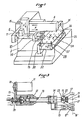
- Figure 1 is a schematic perspective view illustrating the overall morphology of the manipulator machine
- Figure 2 is a schematic plan view corresponding to Figure 1
- Figure 3 is a detail view in partial section of the wrist of the machine.
- the reference 1 designates a dashed line frame schematically materializing the outline of the machine tool, here a lathe, with which is associated the manipulator automaton of the invention, and reference 2 the mandrel of the lathe in which the parts must be put in place.
- Reference 3 designates the frame of the manipulator automaton in which is included the cabinet containing the control electronics and in particular the programmable computer.
- the reference 4 designates the box forming an arm which materializes the X axis.
- the X axis therefore the box 4 is perpendicular to the axis A of the mandrel 2.
- the means guide preferably constituted by ball bushings integral with the carriage 5 rolling on two parallel horizontal bars integral with the box 4.
- the carriage 5 carries the box 6 also horizontal and perpendicular to the box 4, box 6 which materializes the Y axis
- the means controlling the movement of the carriage 5 which are preferably constituted by a stepping motor not shown, the toothed output pinion of which drives a toothed belt mounted in a horizontal loop and at a point from which the carriage 5 is anchored.
- a carriage 7 which carries a vertical box 8 forming the displacement arm along the Z axis
- a carriage 9 which carries the wrist 10 described in more detail below with reference to the fig. re 3.
- the wrist 10 comprises a stepping drive motor 11 fixed on the carriage 9 and a casing of generally cylindrical shape 12 which is parallel to the X axis, that is to say to the casing 4.
- this casing 12 is rotatably mounted the shaft 13 on the end of which is fixed integral with the rotation of the base 14 of the gripping pliers 15.
- the two pliers 15 have their orthogonal action planes, that is to say that when the axis 16 from which the branches 17 of one of the clamps deviate or approach each other is horizontal (Fig. 3), the corresponding axis 16 ⁇ of the branches 17 ⁇ of the other clamp 15 is vertical.
- the clamps 15 are further mounted on the base 14 to be equidistant from the axis of the shaft 13 so that they are substituted in their positions by 90 ° rotations of the shaft 13.
- the rotation of the shaft 13 is controlled from the motor 11 by a transmission comprising the output pinion 18 of the motor 11, a toothed belt 19 and a pinion 20 wedged on the shaft 13.
- the opening and closing of the clamps 15 are controlled by rods 22 actuated from a double-acting cylinder via a connecting piece 23.
- the states of the two control cylinders controlling the clamps 15 are controlled by magnetic sensors and their air supply is ensured by a compressed air, not shown, which passes with the electrical conductors in the hollow shaft 13.
- Reference 21 designates a pneumatic pusher mounted on that of the two pliers which has the role of placing the parts in the man drin 2.
- the clamp holder moves along the Y axis to engage the piece in the jaws, the clamp 17 opens and simultaneously the pressure exerted by the pusher 21 applies the part to the internal stop of the jaws or to a stop placed inside the spindle of the lathe, after which the jaws of the mandrel close and the clamp 17 is released.
- a plate 24 which has in its surface marked locations, in particular housings 25, for the parts and housings such as orifices 26 for positioning the plate 24 on the rods 27 of cylinders 28.
- the plate 24 carrying the workpieces is brought manually or by any conveyor to a loading station delimited by the dashed lines 29.
- a box 30 is mounted in front of the frame 3, towards the machine tool 1 served, box which is horizontal, transverse to the X axis and below the volume in which the clamps 15 move by combining displacements along the X, Y and Z axes.
- This box carries a carriage 31 which is guided and moved in a controlled manner from the same way as the carriages 5, 7 and 9 in the boxes 4, 6 and 8.
- the carriage 31 carries a base plate 32 at the four corners of which are fixed the jacks 28 whose position, and hence the position of the plate 24 engaged through the holes 26 on the rods 27 of the jacks 28, can be precisely controlled in the direction of the arrows P.
- the cha riot 31 brings the jacks 28 in coincidence with the orifices 26 of the tray and the jacks 28 are elongated to lift the tray along the vertical axis V.
- the carriage 31 is then moved in the direction P to bring the tray below the box 4 in the area accessible by the clamps 15, the plate being able to be moved into the position shown in dotted line at 33 (Fig.
Landscapes
- Engineering & Computer Science (AREA)
- Mechanical Engineering (AREA)
- Robotics (AREA)
- Manipulator (AREA)
Applications Claiming Priority (2)
| Application Number | Priority Date | Filing Date | Title |
|---|---|---|---|
| FR8703892A FR2612443A1 (fr) | 1987-03-20 | 1987-03-20 | Automate manipulateur programmable pour la desserte d'une machine-outil |
| FR8703892 | 1987-03-20 |
Publications (1)
| Publication Number | Publication Date |
|---|---|
| EP0283403A1 true EP0283403A1 (de) | 1988-09-21 |
Family
ID=9349247
Family Applications (1)
| Application Number | Title | Priority Date | Filing Date |
|---|---|---|---|
| EP88400654A Withdrawn EP0283403A1 (de) | 1987-03-20 | 1988-03-18 | Handhabungsgerät zum Bestücken einer Werkzeugmaschine |
Country Status (2)
| Country | Link |
|---|---|
| EP (1) | EP0283403A1 (de) |
| FR (1) | FR2612443A1 (de) |
Cited By (10)
| Publication number | Priority date | Publication date | Assignee | Title |
|---|---|---|---|---|
| EP0753378A1 (de) * | 1995-07-13 | 1997-01-15 | ROTOX GmbH B. EISENBACH | Vorrichtung zum Transportieren, Positionieren und/oder Verschwenken eines Rahmens sowie Verfahren hierzu |
| EP0992317A3 (de) * | 1998-10-09 | 2001-05-09 | Murata Kikai Kabushiki Kaisha | Werkstückübergabevorrichtung |
| CN103420154A (zh) * | 2012-05-21 | 2013-12-04 | 昆山瀚崴自动化设备有限公司 | 一种机械手夹取机 |
| EP3006167A1 (de) * | 2014-09-30 | 2016-04-13 | Canon Kabushiki Kaisha | Vorrichtung zur automatisierten montage, system zur automatisierten montage und verfahren zur automatisierten montage |
| CN107584547A (zh) * | 2017-10-30 | 2018-01-16 | 东莞市科立电子设备有限公司 | 一种全自动在线式曲线分板机 |
| CN107838914A (zh) * | 2017-10-27 | 2018-03-27 | 歌尔股份有限公司 | 夹取装置 |
| CN108681226A (zh) * | 2018-05-22 | 2018-10-19 | 中山市方越电子科技有限公司 | 贴密封件装置及处理盒装配生产线 |
| CN108907717A (zh) * | 2018-08-21 | 2018-11-30 | 苏州韦尔迪机电自动化有限公司 | 用于精密零件焊接中心的正面盖板测压移栽机械手 |
| CN108941617A (zh) * | 2018-09-14 | 2018-12-07 | 武创智达科技(杭州)有限公司 | 一种机械手及其生产方式 |
| CN116475847A (zh) * | 2022-01-13 | 2023-07-25 | 贵州兴富祥立健机械有限公司 | 一种全自动化数控机床 |
Citations (5)
| Publication number | Priority date | Publication date | Assignee | Title |
|---|---|---|---|---|
| DE1237005B (de) * | 1963-08-07 | 1967-03-16 | Guenter Burghardt | Werkstueckfoerderanlage mit Aufnahmen fuer die geordnete Lagerung mehrerer Werkstuecke |
| DE2257577A1 (de) * | 1972-01-20 | 1973-07-26 | Werkzeugmasch Okt Veb | Werkstueckwechseleinrichtung fuer werkzeugmaschinen |
| GB1448863A (en) * | 1973-03-07 | 1976-09-08 | Clarke Chapman Ltd | Mechanical handling |
| EP0021972A1 (de) * | 1979-06-15 | 1981-01-07 | SORMEL Société anonyme dite: | Präziser Manipulator mit erhöhter Kadenz |
| WO1985001002A1 (fr) * | 1983-08-26 | 1985-03-14 | C O D Inter Techniques Sa | Robot d'assemblage comprenant un dispositif de transport collectif des pieces a assembler, procede d'assemblage et son application |
-
1987
- 1987-03-20 FR FR8703892A patent/FR2612443A1/fr active Pending
-
1988
- 1988-03-18 EP EP88400654A patent/EP0283403A1/de not_active Withdrawn
Patent Citations (5)
| Publication number | Priority date | Publication date | Assignee | Title |
|---|---|---|---|---|
| DE1237005B (de) * | 1963-08-07 | 1967-03-16 | Guenter Burghardt | Werkstueckfoerderanlage mit Aufnahmen fuer die geordnete Lagerung mehrerer Werkstuecke |
| DE2257577A1 (de) * | 1972-01-20 | 1973-07-26 | Werkzeugmasch Okt Veb | Werkstueckwechseleinrichtung fuer werkzeugmaschinen |
| GB1448863A (en) * | 1973-03-07 | 1976-09-08 | Clarke Chapman Ltd | Mechanical handling |
| EP0021972A1 (de) * | 1979-06-15 | 1981-01-07 | SORMEL Société anonyme dite: | Präziser Manipulator mit erhöhter Kadenz |
| WO1985001002A1 (fr) * | 1983-08-26 | 1985-03-14 | C O D Inter Techniques Sa | Robot d'assemblage comprenant un dispositif de transport collectif des pieces a assembler, procede d'assemblage et son application |
Non-Patent Citations (1)
| Title |
|---|
| IBM TECHNICAL DISCLOSURE BULLETIN, vol. 26, no. 4, septembre 1983, pages 1822-1823, New York, US; R.L. KAFTAN et al.: "Multi-gripper robot" * |
Cited By (13)
| Publication number | Priority date | Publication date | Assignee | Title |
|---|---|---|---|---|
| EP0753378A1 (de) * | 1995-07-13 | 1997-01-15 | ROTOX GmbH B. EISENBACH | Vorrichtung zum Transportieren, Positionieren und/oder Verschwenken eines Rahmens sowie Verfahren hierzu |
| EP0992317A3 (de) * | 1998-10-09 | 2001-05-09 | Murata Kikai Kabushiki Kaisha | Werkstückübergabevorrichtung |
| CN103420154A (zh) * | 2012-05-21 | 2013-12-04 | 昆山瀚崴自动化设备有限公司 | 一种机械手夹取机 |
| CN103420154B (zh) * | 2012-05-21 | 2015-07-08 | 昆山瀚崴自动化设备有限公司 | 一种机械手夹取机 |
| US10252384B2 (en) | 2014-09-30 | 2019-04-09 | Canon Kabushiki Kaisha | Automated assembly apparatus and automated assembly method |
| EP3006167A1 (de) * | 2014-09-30 | 2016-04-13 | Canon Kabushiki Kaisha | Vorrichtung zur automatisierten montage, system zur automatisierten montage und verfahren zur automatisierten montage |
| US10780536B2 (en) | 2014-09-30 | 2020-09-22 | Canon Kabushiki Kaisha | Automated assembly system and automated assembly method |
| CN107838914A (zh) * | 2017-10-27 | 2018-03-27 | 歌尔股份有限公司 | 夹取装置 |
| CN107584547A (zh) * | 2017-10-30 | 2018-01-16 | 东莞市科立电子设备有限公司 | 一种全自动在线式曲线分板机 |
| CN108681226A (zh) * | 2018-05-22 | 2018-10-19 | 中山市方越电子科技有限公司 | 贴密封件装置及处理盒装配生产线 |
| CN108907717A (zh) * | 2018-08-21 | 2018-11-30 | 苏州韦尔迪机电自动化有限公司 | 用于精密零件焊接中心的正面盖板测压移栽机械手 |
| CN108941617A (zh) * | 2018-09-14 | 2018-12-07 | 武创智达科技(杭州)有限公司 | 一种机械手及其生产方式 |
| CN116475847A (zh) * | 2022-01-13 | 2023-07-25 | 贵州兴富祥立健机械有限公司 | 一种全自动化数控机床 |
Also Published As
| Publication number | Publication date |
|---|---|
| FR2612443A1 (fr) | 1988-09-23 |
Similar Documents
| Publication | Publication Date | Title |
|---|---|---|
| FR2468439A1 (fr) | Installation pour la fabrication ou la manipulation de pieces | |
| FR2469981A1 (fr) | Machine video tournante de centrage, d'orientation et de transfert de pieces | |
| FR2482502A1 (fr) | Systeme de manutention de pieces a usiner entre un magasin et une machine-outil | |
| FR2583727A1 (fr) | Appareil de positionnement et chargeur pour dispositif transporteur utilisable notamment pour des isolateurs de bougies d'allumage avant frittage. | |
| FR2652529A1 (fr) | Robot. | |
| EP0283403A1 (de) | Handhabungsgerät zum Bestücken einer Werkzeugmaschine | |
| FR2574691A1 (fr) | Procede et appareil pour monter des pieces des deux cotes d'un corps principal, notamment la carrosserie d'un vehicule automobile | |
| FR2508362A1 (fr) | Machine automatique d'assemblage | |
| FR2732633A1 (fr) | Procede et dispositif de changement d'outil pour un centre d'usinage | |
| EP0185286A1 (de) | Verfahren zum automatischen Beschicken von Bearbeitungsstationen und Vorrichtung zur Durchführung des Verfahrens | |
| FR2639275A1 (fr) | Procede et appareil de transport de pieces pour machine de coupe | |
| EP0243236A1 (de) | Vorrichtung zum Überbringen von Gegenständen, insbesondere Glasplatten | |
| EP0233799B1 (de) | Vorrichtung zum Stellen eines runden Werkstückes an eine Arbeitsstelle | |
| EP0130096B1 (de) | Anlage zur Herstellung von Hemdenmanschetten | |
| EP0649149B1 (de) | Anordnung zur Entnahme von Flüssigkeitsproben aus mit Schraubverschlüssen geschlossenen Behältern | |
| EP3520957B1 (de) | Fördervorrichtung für auf paletten gelagerten teilen, die in der nähe eines verabeitungszentrums positionierbar ist | |
| EP0033689B1 (de) | Automatische Transfervorrichtung für Gegenstände | |
| WO1986002305A1 (fr) | Machine-outil modulaire pour l'usinage de pieces en serie dans une barre | |
| FR2651163A1 (fr) | Dispositif pour recevoir et transferer des pieces a la sortie d'une tronconneuse. | |
| EP0091421A1 (de) | Verfahren und Vorrichtung zum Behandeln von Gegenständen | |
| EP0407537B1 (de) | Maschine und verfahren zum bearbeiten und/oder fertigbearbeiten von gegossenen oder bearbeiteten werkstücken | |
| EP0090753B1 (de) | Maschine zum automatischen Einsetzen von elektronischen Bauelementen, insbesondere von integrierten Bauelementen in Leiterplatten | |
| FR2566742A1 (fr) | Installation de palettisation automatique a outils prehenseurs interchangeables | |
| EP0038740A1 (de) | Maschine zum Abtrennen von Speisern bei Gussstücken | |
| FR2511283A1 (fr) | Dispositif de changement automatique d'outil pour machine-outil |
Legal Events
| Date | Code | Title | Description |
|---|---|---|---|
| PUAI | Public reference made under article 153(3) epc to a published international application that has entered the european phase |
Free format text: ORIGINAL CODE: 0009012 |
|
| AK | Designated contracting states |
Kind code of ref document: A1 Designated state(s): AT BE CH DE ES GB IT LI NL SE |
|
| STAA | Information on the status of an ep patent application or granted ep patent |
Free format text: STATUS: THE APPLICATION IS DEEMED TO BE WITHDRAWN |
|
| 18D | Application deemed to be withdrawn |
Effective date: 19890527 |