EP0283429A2 - Circuit pour la signalisation d'un appel pour un appareil terminal qui est branché sur un réseau téléphonique numérique - Google Patents
Circuit pour la signalisation d'un appel pour un appareil terminal qui est branché sur un réseau téléphonique numérique Download PDFInfo
- Publication number
- EP0283429A2 EP0283429A2 EP88730069A EP88730069A EP0283429A2 EP 0283429 A2 EP0283429 A2 EP 0283429A2 EP 88730069 A EP88730069 A EP 88730069A EP 88730069 A EP88730069 A EP 88730069A EP 0283429 A2 EP0283429 A2 EP 0283429A2
- Authority
- EP
- European Patent Office
- Prior art keywords
- circuit arrangement
- arrangement according
- circuit
- signal
- signal device
- Prior art date
- Legal status (The legal status is an assumption and is not a legal conclusion. Google has not performed a legal analysis and makes no representation as to the accuracy of the status listed.)
- Withdrawn
Links
Images

Classifications
-
- H—ELECTRICITY
- H04—ELECTRIC COMMUNICATION TECHNIQUE
- H04M—TELEPHONIC COMMUNICATION
- H04M19/00—Current supply arrangements for telephone systems
- H04M19/02—Current supply arrangements for telephone systems providing ringing current or supervisory tones, e.g. dialling tone or busy tone
- H04M19/04—Current supply arrangements for telephone systems providing ringing current or supervisory tones, e.g. dialling tone or busy tone the ringing-current being generated at the substations
-
- H—ELECTRICITY
- H04—ELECTRIC COMMUNICATION TECHNIQUE
- H04Q—SELECTING
- H04Q1/00—Details of selecting apparatus or arrangements
- H04Q1/18—Electrical details
- H04Q1/30—Signalling arrangements; Manipulation of signalling currents
- H04Q1/38—Signalling arrangements; Manipulation of signalling currents using combinations of direct currents of different amplitudes or polarities over line conductors or combination of line conductors
Definitions
- the invention relates to a circuit arrangement for signaling a call for a terminal switched into a digital telephone network according to the preamble of claim 1.
- ISDN integrated services digital network
- a channel structure of two digital base channels with 64 kbit / s and a digital control channel with a bit rate of 16 kbit / s is provided for the transmission of information.
- This channel structure enables a parallel connection of different terminals, for example Telephone sets, screen text, facsimile and so on are possible while using two services at the same time.
- additional devices must meet the conditions of the interfaces of the end devices. For example, devices such as call identifiers and secondary alarm clocks are operated on the so-called simple Y interface.
- the invention has for its object to provide a circuit arrangement for signaling a call for a terminal switched into a digital telephone network, which is adapted to the interface condition specified by the digital telephone network.
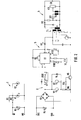
- the 1 shows an interface adaptation circuit 1 and a control circuit 2 below it.
- the terminals W and M1 of the adaptation circuit 1 are located on the simple Y interface of a terminal, for example a telephone set, which is designed for the digital network.
- the matching circuit 1 has two anti-parallel transmit diodes from two optocouplers V1, V2, which are connected on the one hand via the parallel resistors R1, R2 and on the other hand directly to the terminals W, M1.
- a switch S1 In the input line to terminal W there is a switch S1 with which the entire circuit arrangement can be switched on or off.
- a varistor R3 is connected in parallel to the input terminals.
- the control circuit 2 is supplied with a DC voltage of 40 V, which is connected to the terminals SV1 and SV2.
- a varistor R4 is again connected in parallel with these terminals as overvoltage protection.
- a rectifier bridge V3 serves for polarity-independent supply of the control circuit 2.
- the photo receivers of the optocouplers V1, V2 are on the one hand at the bridge connection having positive potential and on the other hand via a resistor R6 at the bridge connection having negative potential.
- a protective diode V4 is provided in parallel with the photo receivers of the optocouplers V1, V2.
- a switching transistor V6 is connected via a resistor R5, the emitter of which is at the negative potential or ground and the collector of which is connected to a relay K1, which on the other hand is connected to the terminal line with positive potential is connected.
- a protection diode V5 is connected in parallel with relay K1.
- the digital call signal which has an idle level (0) and an active level (1), reaches the input terminals W, M1 of the matching circuit 1 and excites one of the transmission diodes of the optocouplers V1, V2 to emit radiation.
- the anti-parallel connection ensures reliable function even if the signal lines are reversed.
- the photo receivers of the optocouplers V1, V2 are switched through, so that the potential at the base of the switching transistor V6 shifts to positive values, as a result of which the transistor V6 switches through and excites the relay K1.
- the contact k1, formed as a make contact, of the relay K1 in the power circuit 3 thus closes in rhythm with the call, as a result of which the signal device 4 in the power circuit 3 is excited.
- the power circuit 3 is thus galvanically isolated from the control circuit 2 as well as from the matching circuit 1 or from the telecommunications circuit.
- the structure of the matching circuit 1 and the control circuit 2 is essentially the same, but instead of the relay K1, optical and acoustic signal devices 5, H2, 6 are provided, which are also supplied by the DC voltage at the terminals SV1, SV2.
- the acoustic signal device has an integrated circuit D1 which contains dividers and, depending on the signal supplied by the transistor V6, supplies electrical signals to a piezo element H1, by means of which they are converted into the desired ones acoustic signals are implemented.
- the dividers in the integrated circuit D1 divide the resonance frequency supplied by a resonator G1 into three different frequencies, so that a three-tone is generated.
- the volume can be adjusted with a potentiometer R102 located between the output of the integrated circuit D1 and the piezo element H1. Furthermore, a potentiometer R103 is provided via a potentiometer connected to other inputs of the integrated circuit D1, with which the tone repetition frequency or repetition frequency of the three tone frequencies can be set, the dividers contained in the integrated circuit D1 likewise changing the frequency specified by the resonator G1 to the desired repetition frequency split down.
- the optical signal device H2 is designed as a light-emitting diode, which lies in the supply current path of the integrated circuit D1.
- the optical signaling is implemented by an electron flash H3.
- the energy supply of the optical signal device 6 likewise takes place from the supply current of the integrated circuit D1 of the acoustic signal generator 5, the primary side of a self-oscillating transmitter T1 being connected between transistor V6 and light-emitting diode H2 or integrated circuit D1.
- the voltage is stepped up on the secondary side, rectified via the diode V9 and charges a capacitor C6 connected in parallel with a flash lamp H3 until the discharge vessel V11 ignites and via the ignition transformer T2 controls and ignites the flash lamp H3.
- the residual energy of the capacitor C6 discharges in the spark gap of the flash lamp H3.
- a constant current source is connected, which has a field effect transistor V7 and an adjustable resistor R101, the resistor R101 being set such that at least two flashes per call can be generated and that the sound pressure of the acoustic signal generator 5 has a certain level.
- the constant current source also serves to limit the current supplied to the signaling devices.
Landscapes
- Engineering & Computer Science (AREA)
- Signal Processing (AREA)
- Computer Networks & Wireless Communication (AREA)
- Telephonic Communication Services (AREA)
- Interface Circuits In Exchanges (AREA)
- Telephone Function (AREA)
- Cable Transmission Systems, Equalization Of Radio And Reduction Of Echo (AREA)
Applications Claiming Priority (2)
| Application Number | Priority Date | Filing Date | Title |
|---|---|---|---|
| DE3709012 | 1987-03-19 | ||
| DE19873709012 DE3709012A1 (de) | 1987-03-19 | 1987-03-19 | Schaltungsanordnung zur signalisierung eines anrufes fuer ein in ein digitales fernsprechnetz geschaltetes endgeraet |
Publications (2)
| Publication Number | Publication Date |
|---|---|
| EP0283429A2 true EP0283429A2 (fr) | 1988-09-21 |
| EP0283429A3 EP0283429A3 (fr) | 1990-05-09 |
Family
ID=6323506
Family Applications (1)
| Application Number | Title | Priority Date | Filing Date |
|---|---|---|---|
| EP88730069A Withdrawn EP0283429A3 (fr) | 1987-03-19 | 1988-03-18 | Circuit pour la signalisation d'un appel pour un appareil terminal qui est branché sur un réseau téléphonique numérique |
Country Status (3)
| Country | Link |
|---|---|
| EP (1) | EP0283429A3 (fr) |
| DE (1) | DE3709012A1 (fr) |
| NO (1) | NO881198L (fr) |
Families Citing this family (6)
| Publication number | Priority date | Publication date | Assignee | Title |
|---|---|---|---|---|
| DE3716140A1 (de) * | 1987-05-14 | 1988-11-24 | Rutenbeck Wilhelm Gmbh & Co | Starkstromanschlussrelais (sar) fuer nach dem isdn-system betriebene fernsprechnetze |
| JP2820955B2 (ja) * | 1989-04-27 | 1998-11-05 | 株式会社リコー | 網制御装置 |
| DE4113758C2 (de) * | 1991-04-26 | 1994-04-28 | Siemens Ag | Schaltungsanordnung für eine transistorisierte Fernsprechstation mit Zweitwecker |
| DE4214125C1 (de) * | 1992-04-29 | 1993-10-21 | Siemens Ag | Verfahren zur Pegel- und Frequenzüberwachung bei der Übertragung von leitungsgebundenen Signalen für signalabhängige Vorgänge, insbesondere Tonrufeingangssignale zur Auslösung eines Tonrufes in Fernsprechendgeräten |
| DE4425824C2 (de) * | 1994-07-08 | 1997-01-30 | Deutsche Telephonwerk Kabel | Vollelektronischer, einpoliger Schalter |
| DE19612485A1 (de) * | 1996-03-29 | 1997-10-02 | Deutsche Telekom Ag | Vorrichtung zum externen Anschalten wenigstens einer Zusatzeinrichtung an eine digitale Telekommunikationseinrichtung |
Family Cites Families (8)
| Publication number | Priority date | Publication date | Assignee | Title |
|---|---|---|---|---|
| DE2758542A1 (de) * | 1977-12-23 | 1979-06-28 | Elmeg | Amtsanruf-schaltung |
| DE2831125C2 (de) * | 1978-07-12 | 1980-07-03 | Bezet-Werk Hermann Buchholz Gmbh, 1000 Berlin | Verfahren zum optischen Anzeigen des Telefonrufes und Schaltung zur Durchführung des Verfahrens |
| GB2064268B (en) * | 1979-09-17 | 1983-10-26 | Philips Nv | Electronic signalling device for connection to a signal transmission line |
| DE3000278C2 (de) * | 1980-01-05 | 1986-05-28 | Neumann Elektronik GmbH, 4330 Mülheim | Elektrooptischer Wecker |
| US4467144A (en) * | 1982-04-08 | 1984-08-21 | Amf Incorporated | Telephone annuciator extender |
| DE3541547A1 (de) * | 1985-11-25 | 1987-05-27 | Ant Nachrichtentech | Rufspannungsauswertung |
| DE3612684A1 (de) * | 1986-04-15 | 1987-10-22 | Heilmeier & Weinlein | Hydraulische steuervorrichtung |
| DE3716140A1 (de) * | 1987-05-14 | 1988-11-24 | Rutenbeck Wilhelm Gmbh & Co | Starkstromanschlussrelais (sar) fuer nach dem isdn-system betriebene fernsprechnetze |
-
1987
- 1987-03-19 DE DE19873709012 patent/DE3709012A1/de not_active Ceased
-
1988
- 1988-03-18 NO NO881198A patent/NO881198L/no unknown
- 1988-03-18 EP EP88730069A patent/EP0283429A3/fr not_active Withdrawn
Also Published As
| Publication number | Publication date |
|---|---|
| NO881198L (no) | 1988-09-20 |
| DE3709012A1 (de) | 1988-09-29 |
| EP0283429A3 (fr) | 1990-05-09 |
| NO881198D0 (no) | 1988-03-18 |
Similar Documents
| Publication | Publication Date | Title |
|---|---|---|
| DE3632746C2 (de) | Schaltungsanordnung zur Erzeugung einer Wechselspannung | |
| DE2850841C2 (de) | Schaltungsanordnung für ein integrierbares elektronisches Relais | |
| DE2627199A1 (de) | Schutzeinrichtung fuer ein teilnehmergeraet | |
| DE68919558T2 (de) | Schleifenstromreguliereinrichtung für eine Fernsprechleitung. | |
| DE2800159A1 (de) | Konstantstrom-versorgungsschaltung fuer fernsprechteilnehmerleitungen | |
| DE2800158A1 (de) | Fernsprechleitungs-schnittstellenschaltung | |
| EP0283429A2 (fr) | Circuit pour la signalisation d'un appel pour un appareil terminal qui est branché sur un réseau téléphonique numérique | |
| DE3318843A1 (de) | Photographisches blitzentladungsgeraet | |
| DE68926155T2 (de) | Halbleiterschaltung mit einer Überspannungsschutzschaltung | |
| DE3640905A1 (de) | Schaltungsanordnung zur speisung von teilnehmerleitungen mit konstantem strom | |
| DE2201764B2 (de) | Schaltungsanordnung zum Umsetzen eines elektrischen Rufsignals in ein akustisches Rufsignal in Fernmeldeanlagen, insbesondere Tonwecker | |
| DE2641967B2 (de) | Schaltungsanordnung für einen Fernsprechapparat mit Wähltastatur, nach dem Impulswahlverfahren | |
| CH635216A5 (de) | Geraet zur ueberwachung des linienstromes in einer telefonleitung. | |
| DE3783909T2 (de) | Anordnung zur berichtsmeldung in einem fernsprechsystem. | |
| DE69231822T2 (de) | Treiberschnittstelle für einen telephonischen Leitungschalter zum Einschalten einer Sprechschaltung unabhängig von der Leistungspolarität | |
| DE2540857C2 (de) | Schaltungsanordnung zum induktiven Einspeisen einer getakteten Hörtonspannung in Leitungen, insbesondere Fernsprechleitungen | |
| EP0499869B1 (fr) | Circuit pour génération de tension alternative | |
| DE1219528B (de) | Stromversorgungsschaltung fuer eine Waehlscheibenbeleuchtung an Fernsprechteilnehmerapparaten | |
| DE1144345B (de) | Schaltungsanordnung zum Empfangen von Gleichstromsignalen in Fernmelde-, insbesondere Fernsprechvermittlungsanlagen | |
| EP0108228A2 (fr) | Poste téléphonique consommant peu d'énergie | |
| DE2203857B2 (de) | Schaltungsanordnung zur Erzeugung eines akustischen Rufsignals für Endstellen in Fernmelde-, insbesondere Fernsprechanlagen mittels einer Schwingschaltung | |
| DE2302024C3 (de) | Schaltungsanordnung zum Anschließen von Telegrafie- und Datenteilnehmern an eine Vermittlungsanlage | |
| DE3627025C2 (fr) | ||
| DE19635289A1 (de) | Stromversorgungssteuerschaltung in einem Mobilfunk-Kommunikationssystem | |
| DE2548679A1 (de) | Schaltungsanordnung zur ansteuerung eines mehrfrequenzoszillators fuer teilnehmerstationen |
Legal Events
| Date | Code | Title | Description |
|---|---|---|---|
| PUAI | Public reference made under article 153(3) epc to a published international application that has entered the european phase |
Free format text: ORIGINAL CODE: 0009012 |
|
| AK | Designated contracting states |
Kind code of ref document: A2 Designated state(s): AT BE CH DE LI NL SE |
|
| PUAL | Search report despatched |
Free format text: ORIGINAL CODE: 0009013 |
|
| AK | Designated contracting states |
Kind code of ref document: A3 Designated state(s): AT BE CH DE LI NL SE |
|
| STAA | Information on the status of an ep patent application or granted ep patent |
Free format text: STATUS: THE APPLICATION IS DEEMED TO BE WITHDRAWN |
|
| 18D | Application deemed to be withdrawn |
Effective date: 19901003 |