EP0283532A1 - Presse à couper et déformer à entraînement à genouillère hydro-mécanique - Google Patents
Presse à couper et déformer à entraînement à genouillère hydro-mécanique Download PDFInfo
- Publication number
- EP0283532A1 EP0283532A1 EP87104278A EP87104278A EP0283532A1 EP 0283532 A1 EP0283532 A1 EP 0283532A1 EP 87104278 A EP87104278 A EP 87104278A EP 87104278 A EP87104278 A EP 87104278A EP 0283532 A1 EP0283532 A1 EP 0283532A1
- Authority
- EP
- European Patent Office
- Prior art keywords
- press
- cutting
- center
- articulation
- plunger
- Prior art date
- Legal status (The legal status is an assumption and is not a legal conclusion. Google has not performed a legal analysis and makes no representation as to the accuracy of the status listed.)
- Granted
Links
- 238000005520 cutting process Methods 0.000 title claims abstract description 7
- 238000010276 construction Methods 0.000 claims description 9
- 238000012546 transfer Methods 0.000 claims description 2
- 230000005540 biological transmission Effects 0.000 description 3
- 239000000725 suspension Substances 0.000 description 3
- 238000000418 atomic force spectrum Methods 0.000 description 2
- 238000011161 development Methods 0.000 description 2
- 238000011835 investigation Methods 0.000 description 2
- 238000004519 manufacturing process Methods 0.000 description 2
- 239000002184 metal Substances 0.000 description 2
- 238000000034 method Methods 0.000 description 2
- 230000001427 coherent effect Effects 0.000 description 1
- 230000007423 decrease Effects 0.000 description 1
- 238000013461 design Methods 0.000 description 1
- 230000000694 effects Effects 0.000 description 1
- 238000004049 embossing Methods 0.000 description 1
- 238000009434 installation Methods 0.000 description 1
- 238000011838 internal investigation Methods 0.000 description 1
- 210000000629 knee joint Anatomy 0.000 description 1
- 239000000463 material Substances 0.000 description 1
- 239000000256 polyoxyethylene sorbitan monolaurate Substances 0.000 description 1
- 238000004080 punching Methods 0.000 description 1
- 238000013519 translation Methods 0.000 description 1
Images

Classifications
-
- B—PERFORMING OPERATIONS; TRANSPORTING
- B30—PRESSES
- B30B—PRESSES IN GENERAL
- B30B1/00—Presses, using a press ram, characterised by the features of the drive therefor, pressure being transmitted directly, or through simple thrust or tension members only, to the press ram or platen
- B30B1/10—Presses, using a press ram, characterised by the features of the drive therefor, pressure being transmitted directly, or through simple thrust or tension members only, to the press ram or platen by toggle mechanism
- B30B1/16—Presses, using a press ram, characterised by the features of the drive therefor, pressure being transmitted directly, or through simple thrust or tension members only, to the press ram or platen by toggle mechanism operated by fluid-pressure means
-
- B—PERFORMING OPERATIONS; TRANSPORTING
- B21—MECHANICAL METAL-WORKING WITHOUT ESSENTIALLY REMOVING MATERIAL; PUNCHING METAL
- B21J—FORGING; HAMMERING; PRESSING METAL; RIVETING; FORGE FURNACES
- B21J9/00—Forging presses
- B21J9/10—Drives for forging presses
- B21J9/18—Drives for forging presses operated by making use of gearing mechanisms, e.g. levers, spindles, crankshafts, eccentrics, toggle-levers, rack bars
-
- B—PERFORMING OPERATIONS; TRANSPORTING
- B30—PRESSES
- B30B—PRESSES IN GENERAL
- B30B15/00—Details of, or accessories for, presses; Auxiliary measures in connection with pressing
- B30B15/0029—Details of, or accessories for, presses; Auxiliary measures in connection with pressing means for adjusting the space between the press slide and the press table, i.e. the shut height
-
- Y—GENERAL TAGGING OF NEW TECHNOLOGICAL DEVELOPMENTS; GENERAL TAGGING OF CROSS-SECTIONAL TECHNOLOGIES SPANNING OVER SEVERAL SECTIONS OF THE IPC; TECHNICAL SUBJECTS COVERED BY FORMER USPC CROSS-REFERENCE ART COLLECTIONS [XRACs] AND DIGESTS
- Y10—TECHNICAL SUBJECTS COVERED BY FORMER USPC
- Y10T—TECHNICAL SUBJECTS COVERED BY FORMER US CLASSIFICATION
- Y10T83/00—Cutting
- Y10T83/869—Means to drive or to guide tool
- Y10T83/8821—With simple rectilinear reciprocating motion only
- Y10T83/8841—Tool driver movable relative to tool support
- Y10T83/8845—Toggle links, one link pivoted to tool support
Definitions
- the invention relates to a cutting and forming press with a hydro-mechanical articulated lever drive, in which the drive cylinder for the plunger is carried by a bridge construction arranged in the stand between lateral guides, via a bridge construction connected to these by means of threaded spindles or other height-adjustable means, and this within the area of the free space of the frame-shaped stand is adjustable.
- German patent specification 29 25 416 introduced a toggle lever sheet metal cutting press, introduced as a differential travel press, with a pressure medium cylinder drive arranged between two toggle lever systems, which bent out with their knee joints towards the center of the press and were symmetrically the same, the pistons of which had the end of its piston rod at the connecting joint of two handlebars at the center of the press attacks, which are articulated at the other end to the toggle lever systems, the connecting joint with the help of the press ram having a guide transverse to the direction of the piston rod, the criterion of which is the support of the pressure medium cylinder drive on the press ram, wherein according to a further claim the ram is designed as a frame.
- the US-PS 20 37 811 and the GB-PS 8 04 352 were mentioned as the relevant prior art. According to these documents, the stroke of the ram is determined by the stroke of the fixed drive cylinder fixed to the frame, and by the transmission ratio resulting from the toggle lever drive and the type of handlebar in a known manner.
- the bridge construction forms the connection between the bearing axes arranged symmetrically to the center of the press on both sides and the center guide for the piston rod, including its limitation by the articulation point, receives the drive cylinder, that the two bearing axles with further adjoining hinge points form a rigid pivotable triangle, the hinge point directed towards the center of the tappet in each case via at least two coupled drive lever parts leading to the hinge point, which are connected to the hinge points movable in the direction of the center guide, and that the pivot points arranged on both sides in the lower area of the center guide transfer to a separate curve on both sides and the pivot points of the triangle are connected to the plunger by a continuing lever part.
- the further provided pivotable connection of the two hinge points to a rigid pivotable triangle not only simplifies, but also supports the precision of the guidance, the center guidance being distributed in two curves with a U-shaped cross section.
- the branching U-shaped curve guide for the articulation points of a split handlebar on both sides - especially with its rotatable roller design - increases the safety of the guide and reduces the friction losses, so that the pressure can be guided into the plunger according to the translation of the drive parts.
- the pivot point of the triangle directed towards the center of the press leads to a more ideal, more even movement of the cylinder piston rod than the connections provided for differential travel presses.
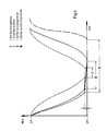
- the guide curve converts the unnecessary but existing force into speed in the lower area.
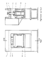
- the frame-shaped press ram 2 is arranged within a free space given by the upper edge of the press table and the lower limit of the upper transverse yoke, as well as the two adjustable guides 12 on the side, and is otherwise connected to a bridge construction 5 which carries the drive cylinder 3 and which, in turn, is height-adjustable to the stand by means of spindles 4 1 is.
- the bridge construction 5 accommodates the bearing axles 6 for the support bearings for the suspension of the pivotable triangles 10, which are additionally marked by the articulation points 8 and 9, on both sides in the area of their lower and lower limits.
- the articulation points 8 form on both sides the connection joint for the continuing levers 13 leading to the plunger 2, while the articulation points 9 each connect the lever parts 10.1 and 10.2 in a joint point 10.3 as a bendable handlebar.
- Item 5 is reinforced by an extension of the guide 5.1.
- articulation points 10.2 are connected to an articulation point 10.4 which is formed at the end of the piston rod 3.1 and is arranged in a sliding manner in the center guide 7.
- the articulation point 10.3 is driven in each case via the lever part 10.2, this being guided in a separate curve 7.1 and connected to the articulation points 9 of the triangles 10 via the lever parts 10.1.
- the curves 7.1 have a U-shaped cross section.
- the hinge point 10.3 is designed as an easily rotatable roller, which is generally carried by a roller bearing.
Landscapes
- Engineering & Computer Science (AREA)
- Mechanical Engineering (AREA)
- Press Drives And Press Lines (AREA)
- Casting Or Compression Moulding Of Plastics Or The Like (AREA)
Priority Applications (5)
| Application Number | Priority Date | Filing Date | Title |
|---|---|---|---|
| DE8787104278T DE3770624D1 (de) | 1987-03-24 | 1987-03-24 | Schneid- und umformpresse mit hydro-mechanischem gelenkantrieb. |
| AT87104278T ATE64118T1 (de) | 1987-03-24 | 1987-03-24 | Schneid- und umformpresse mit hydro-mechanischem gelenkantrieb. |
| EP87104278A EP0283532B1 (fr) | 1987-03-24 | 1987-03-24 | Presse à couper et déformer à entraînement à genouillère hydro-mécanique |
| JP63049922A JPS63256294A (ja) | 1987-03-24 | 1988-03-04 | 流体・機械的トグルジョイント駆動装置 |
| US07/172,696 US4876878A (en) | 1987-03-24 | 1988-03-23 | Press with hydro-mechanical drive |
Applications Claiming Priority (1)
| Application Number | Priority Date | Filing Date | Title |
|---|---|---|---|
| EP87104278A EP0283532B1 (fr) | 1987-03-24 | 1987-03-24 | Presse à couper et déformer à entraînement à genouillère hydro-mécanique |
Publications (2)
| Publication Number | Publication Date |
|---|---|
| EP0283532A1 true EP0283532A1 (fr) | 1988-09-28 |
| EP0283532B1 EP0283532B1 (fr) | 1991-06-05 |
Family
ID=8196861
Family Applications (1)
| Application Number | Title | Priority Date | Filing Date |
|---|---|---|---|
| EP87104278A Expired - Lifetime EP0283532B1 (fr) | 1987-03-24 | 1987-03-24 | Presse à couper et déformer à entraînement à genouillère hydro-mécanique |
Country Status (5)
| Country | Link |
|---|---|
| US (1) | US4876878A (fr) |
| EP (1) | EP0283532B1 (fr) |
| JP (1) | JPS63256294A (fr) |
| AT (1) | ATE64118T1 (fr) |
| DE (1) | DE3770624D1 (fr) |
Cited By (4)
| Publication number | Priority date | Publication date | Assignee | Title |
|---|---|---|---|---|
| DE4220043A1 (de) * | 1992-06-22 | 1993-12-23 | Verhoefen Ulrich | Schneid- und Umformpresse mit einem oder mehreren Antriebzylindern und einem Gelenkhebelantrieb |
| DE4319899A1 (de) * | 1993-06-16 | 1995-01-05 | Leinhaas Umformtechnik Gmbh | Gelenkhebelpresse und Verfahren zur Steuerung der Stößelbewegung |
| CN102442013A (zh) * | 2010-12-13 | 2012-05-09 | 宁波精达成形装备股份有限公司 | 压力机滑块导向机构 |
| DE102019112921A1 (de) * | 2019-05-16 | 2020-11-19 | Dr. Ing. H.C. F. Porsche Aktiengesellschaft | Hebeltrieb |
Citations (5)
| Publication number | Priority date | Publication date | Assignee | Title |
|---|---|---|---|---|
| DE720988C (de) * | 1937-09-14 | 1942-05-21 | Walter Eduard Kaess | Vorrichtung zum Pressen, Praegen, Ziehen, Formen u. dgl. von Gegenstaenden aus Pappe, Karton, insbesondere Frucht- oder Fleischschaelchen aus Fasermaterial |
| DE839759C (de) * | 1948-08-24 | 1952-05-23 | Schwäbisch Gmünd Dr.-Ing. Otto May | Kniehebelpresse |
| DE901130C (de) * | 1949-12-17 | 1954-05-13 | Otto May Dr Ing | Kniehebelpresse |
| GB2052370A (en) * | 1979-06-23 | 1981-01-28 | Leinhaas W | Machine tool with a reciprocating tool carrier |
| DE3517492A1 (de) * | 1984-11-05 | 1986-05-07 | Werner Ing.(Grad.) 6460 Gelnhausen Leinhaas | Kniehebel-blechschneidepresse, bestehend aus einem pressenstaender und einem pressenstoessel |
Family Cites Families (10)
| Publication number | Priority date | Publication date | Assignee | Title |
|---|---|---|---|---|
| GB804352A (en) * | 1955-06-30 | 1958-11-12 | William Frank Golding | Improvements in or relating to power presses |
| FR1322208A (fr) * | 1962-02-12 | 1963-03-29 | Système de fermeture de presse | |
| DE1459339A1 (de) * | 1962-04-12 | 1968-11-28 | Rheinmetall Gmbh | Kniehebelpresse |
| US3611497A (en) * | 1969-05-01 | 1971-10-12 | Nashua Ind Machine Corp | Tie-rodless double acting press |
| US3682029A (en) * | 1970-04-13 | 1972-08-08 | Schwabe Inc Herman | Balanced and double action cutting apparatus |
| US3866503A (en) * | 1973-08-22 | 1975-02-18 | Schjeldahl Co G T | Reciprocatory drive means for treatment of movable webs |
| US4160409A (en) * | 1974-09-03 | 1979-07-10 | Bruderer Ag | Drive for the movable work component, such as the ram of a press, stamping machine or the like |
| SU683836A1 (ru) * | 1976-11-26 | 1979-09-05 | Ленинградский Институт Точной Механики И Оптики | Штамп последовательного действи |
| DE2934286C2 (de) * | 1979-08-24 | 1984-06-14 | L. Schuler GmbH, 7320 Göppingen | Mehrpunkt-Pressenantrieb |
| ATE8756T1 (de) * | 1981-02-11 | 1984-08-15 | L. Schuler Gmbh | Pressenantrieb. |
-
1987
- 1987-03-24 EP EP87104278A patent/EP0283532B1/fr not_active Expired - Lifetime
- 1987-03-24 DE DE8787104278T patent/DE3770624D1/de not_active Expired - Lifetime
- 1987-03-24 AT AT87104278T patent/ATE64118T1/de not_active IP Right Cessation
-
1988
- 1988-03-04 JP JP63049922A patent/JPS63256294A/ja active Pending
- 1988-03-23 US US07/172,696 patent/US4876878A/en not_active Expired - Fee Related
Patent Citations (5)
| Publication number | Priority date | Publication date | Assignee | Title |
|---|---|---|---|---|
| DE720988C (de) * | 1937-09-14 | 1942-05-21 | Walter Eduard Kaess | Vorrichtung zum Pressen, Praegen, Ziehen, Formen u. dgl. von Gegenstaenden aus Pappe, Karton, insbesondere Frucht- oder Fleischschaelchen aus Fasermaterial |
| DE839759C (de) * | 1948-08-24 | 1952-05-23 | Schwäbisch Gmünd Dr.-Ing. Otto May | Kniehebelpresse |
| DE901130C (de) * | 1949-12-17 | 1954-05-13 | Otto May Dr Ing | Kniehebelpresse |
| GB2052370A (en) * | 1979-06-23 | 1981-01-28 | Leinhaas W | Machine tool with a reciprocating tool carrier |
| DE3517492A1 (de) * | 1984-11-05 | 1986-05-07 | Werner Ing.(Grad.) 6460 Gelnhausen Leinhaas | Kniehebel-blechschneidepresse, bestehend aus einem pressenstaender und einem pressenstoessel |
Cited By (6)
| Publication number | Priority date | Publication date | Assignee | Title |
|---|---|---|---|---|
| DE4220043A1 (de) * | 1992-06-22 | 1993-12-23 | Verhoefen Ulrich | Schneid- und Umformpresse mit einem oder mehreren Antriebzylindern und einem Gelenkhebelantrieb |
| EP0576964A1 (fr) * | 1992-06-22 | 1994-01-05 | Ulrich Verhoefen | Presse à découper et à déformer avec un ou plusieurs vérins d'entraînement et à genouillère |
| DE4319899A1 (de) * | 1993-06-16 | 1995-01-05 | Leinhaas Umformtechnik Gmbh | Gelenkhebelpresse und Verfahren zur Steuerung der Stößelbewegung |
| CN102442013A (zh) * | 2010-12-13 | 2012-05-09 | 宁波精达成形装备股份有限公司 | 压力机滑块导向机构 |
| DE102019112921A1 (de) * | 2019-05-16 | 2020-11-19 | Dr. Ing. H.C. F. Porsche Aktiengesellschaft | Hebeltrieb |
| DE102019112921B4 (de) * | 2019-05-16 | 2024-03-07 | Dr. Ing. H.C. F. Porsche Aktiengesellschaft | Hebeltrieb |
Also Published As
| Publication number | Publication date |
|---|---|
| US4876878A (en) | 1989-10-31 |
| ATE64118T1 (de) | 1991-06-15 |
| DE3770624D1 (de) | 1991-07-11 |
| JPS63256294A (ja) | 1988-10-24 |
| EP0283532B1 (fr) | 1991-06-05 |
Similar Documents
| Publication | Publication Date | Title |
|---|---|---|
| DE3517492C2 (fr) | ||
| DE2826316B1 (de) | Durchbiegungseinstellwalze | |
| DE2715688C2 (fr) | ||
| AT507944B1 (de) | Abkantpresse zum biegen von folien | |
| EP0330914B1 (fr) | Dispositif d'éjection des pièces hors des matrices dans une presse de formage | |
| EP0724953B1 (fr) | Poinçonneuse avec espace allongé pour le montage de poinçons | |
| DE2131013A1 (de) | Presse,insbesondere Ziehpresse | |
| DE2742455A1 (de) | Stuetzfuehrungsgeruest in einer stahlstranggiessanlage | |
| DE3328410A1 (de) | Steuergestaenge eines angetriebenen teils, wie zum beispiel ein ausruecklager | |
| DE3008203A1 (de) | Stauchgeruest mit kraftbetrieben anstellbaren walzen | |
| EP0283532B1 (fr) | Presse à couper et déformer à entraînement à genouillère hydro-mécanique | |
| AT392661B (de) | Presswalze, deren durchbiegung einstellbar ist | |
| DE4430216C2 (de) | Mechanische Presse | |
| EP1687104B1 (fr) | Cylindre de reglage dans des cages de laminoir, notamment dans des cages de refoulement verticales | |
| DE102010015922A1 (de) | Abkantpresse zum Biegen von Folien | |
| CH669149A5 (de) | Blechpresse. | |
| AT397624B (de) | Vorrichtung zum biegen von kanten | |
| DE60211080T2 (de) | Verstellbare Formmatrize, insbesondere für Abkantpressen | |
| EP0576964B1 (fr) | Presse à découper et à déformer avec un ou plusieurs vérins d'entraînement et à genouillère | |
| DE69002993T2 (de) | Haupthebel für schnell laufende Drehschaftmaschinen. | |
| DE3338542T1 (de) | Hydraulische Presse | |
| DE3943349C2 (de) | Blechbiegemaschine | |
| DE68918917T2 (de) | Stauchpresse mit horizontal gegenüberliegenden Stempeln. | |
| DE19841471B4 (de) | Vorrichtung zum Stanzen von flächigem Material | |
| DE2536475C3 (de) | Presse zur Ausübung einer Flächenpressung |
Legal Events
| Date | Code | Title | Description |
|---|---|---|---|
| PUAI | Public reference made under article 153(3) epc to a published international application that has entered the european phase |
Free format text: ORIGINAL CODE: 0009012 |
|
| AK | Designated contracting states |
Kind code of ref document: A1 Designated state(s): AT BE CH DE ES FR GB GR IT LI LU NL SE |
|
| RBV | Designated contracting states (corrected) |
Designated state(s): AT CH DE FR GB IT LI SE |
|
| 17P | Request for examination filed |
Effective date: 19890325 |
|
| 17Q | First examination report despatched |
Effective date: 19900612 |
|
| GRAA | (expected) grant |
Free format text: ORIGINAL CODE: 0009210 |
|
| AK | Designated contracting states |
Kind code of ref document: B1 Designated state(s): AT CH DE FR GB IT LI SE |
|
| PG25 | Lapsed in a contracting state [announced via postgrant information from national office to epo] |
Ref country code: SE Effective date: 19910605 |
|
| REF | Corresponds to: |
Ref document number: 64118 Country of ref document: AT Date of ref document: 19910615 Kind code of ref document: T |
|
| ITF | It: translation for a ep patent filed | ||
| REF | Corresponds to: |
Ref document number: 3770624 Country of ref document: DE Date of ref document: 19910711 |
|
| ET | Fr: translation filed | ||
| GBT | Gb: translation of ep patent filed (gb section 77(6)(a)/1977) | ||
| PLBE | No opposition filed within time limit |
Free format text: ORIGINAL CODE: 0009261 |
|
| STAA | Information on the status of an ep patent application or granted ep patent |
Free format text: STATUS: NO OPPOSITION FILED WITHIN TIME LIMIT |
|
| 26N | No opposition filed | ||
| PGFP | Annual fee paid to national office [announced via postgrant information from national office to epo] |
Ref country code: GB Payment date: 19950306 Year of fee payment: 9 |
|
| PGFP | Annual fee paid to national office [announced via postgrant information from national office to epo] |
Ref country code: AT Payment date: 19950324 Year of fee payment: 9 |
|
| PGFP | Annual fee paid to national office [announced via postgrant information from national office to epo] |
Ref country code: CH Payment date: 19950418 Year of fee payment: 9 |
|
| PGFP | Annual fee paid to national office [announced via postgrant information from national office to epo] |
Ref country code: DE Payment date: 19950523 Year of fee payment: 9 |
|
| PG25 | Lapsed in a contracting state [announced via postgrant information from national office to epo] |
Ref country code: GB Effective date: 19960324 Ref country code: AT Effective date: 19960324 |
|
| PG25 | Lapsed in a contracting state [announced via postgrant information from national office to epo] |
Ref country code: LI Effective date: 19960331 Ref country code: CH Effective date: 19960331 |
|
| GBPC | Gb: european patent ceased through non-payment of renewal fee |
Effective date: 19960324 |
|
| REG | Reference to a national code |
Ref country code: CH Ref legal event code: PL |
|
| PG25 | Lapsed in a contracting state [announced via postgrant information from national office to epo] |
Ref country code: DE Effective date: 19961203 |
|
| PGFP | Annual fee paid to national office [announced via postgrant information from national office to epo] |
Ref country code: FR Payment date: 19990728 Year of fee payment: 13 |
|
| PG25 | Lapsed in a contracting state [announced via postgrant information from national office to epo] |
Ref country code: FR Free format text: LAPSE BECAUSE OF NON-PAYMENT OF DUE FEES Effective date: 20001130 |
|
| REG | Reference to a national code |
Ref country code: FR Ref legal event code: ST |
|
| PG25 | Lapsed in a contracting state [announced via postgrant information from national office to epo] |
Ref country code: IT Free format text: LAPSE BECAUSE OF NON-PAYMENT OF DUE FEES;WARNING: LAPSES OF ITALIAN PATENTS WITH EFFECTIVE DATE BEFORE 2007 MAY HAVE OCCURRED AT ANY TIME BEFORE 2007. THE CORRECT EFFECTIVE DATE MAY BE DIFFERENT FROM THE ONE RECORDED. Effective date: 20050324 |