EP0283542A1 - Schallschutzwand - Google Patents
Schallschutzwand Download PDFInfo
- Publication number
- EP0283542A1 EP0283542A1 EP87104535A EP87104535A EP0283542A1 EP 0283542 A1 EP0283542 A1 EP 0283542A1 EP 87104535 A EP87104535 A EP 87104535A EP 87104535 A EP87104535 A EP 87104535A EP 0283542 A1 EP0283542 A1 EP 0283542A1
- Authority
- EP
- European Patent Office
- Prior art keywords
- mats
- wall according
- frame
- soundproof wall
- fastened
- Prior art date
- Legal status (The legal status is an assumption and is not a legal conclusion. Google has not performed a legal analysis and makes no representation as to the accuracy of the status listed.)
- Granted
Links
- 230000004888 barrier function Effects 0.000 title claims description 9
- 239000000463 material Substances 0.000 claims abstract description 6
- 239000004744 fabric Substances 0.000 claims description 2
- 238000010413 gardening Methods 0.000 claims description 2
- 229910000831 Steel Inorganic materials 0.000 claims 1
- 239000010959 steel Substances 0.000 claims 1
- 229910000746 Structural steel Inorganic materials 0.000 abstract description 14
- 238000009434 installation Methods 0.000 description 6
- 239000002689 soil Substances 0.000 description 5
- 244000060011 Cocos nucifera Species 0.000 description 4
- 235000013162 Cocos nucifera Nutrition 0.000 description 4
- 238000010276 construction Methods 0.000 description 2
- 230000002262 irrigation Effects 0.000 description 2
- 238000003973 irrigation Methods 0.000 description 2
- 239000000758 substrate Substances 0.000 description 2
- XLYOFNOQVPJJNP-UHFFFAOYSA-N water Substances O XLYOFNOQVPJJNP-UHFFFAOYSA-N 0.000 description 2
- 244000025254 Cannabis sativa Species 0.000 description 1
- 206010016275 Fear Diseases 0.000 description 1
- 238000010521 absorption reaction Methods 0.000 description 1
- 238000009825 accumulation Methods 0.000 description 1
- 238000005253 cladding Methods 0.000 description 1
- 230000006835 compression Effects 0.000 description 1
- 238000007906 compression Methods 0.000 description 1
- 238000005260 corrosion Methods 0.000 description 1
- 230000007797 corrosion Effects 0.000 description 1
- 239000000945 filler Substances 0.000 description 1
- 238000009415 formwork Methods 0.000 description 1
- 239000004746 geotextile Substances 0.000 description 1
- 238000004519 manufacturing process Methods 0.000 description 1
- 238000000034 method Methods 0.000 description 1
- 239000000203 mixture Substances 0.000 description 1
- NJPPVKZQTLUDBO-UHFFFAOYSA-N novaluron Chemical compound C1=C(Cl)C(OC(F)(F)C(OC(F)(F)F)F)=CC=C1NC(=O)NC(=O)C1=C(F)C=CC=C1F NJPPVKZQTLUDBO-UHFFFAOYSA-N 0.000 description 1
- 230000003287 optical effect Effects 0.000 description 1
- 238000002360 preparation method Methods 0.000 description 1
Images


Classifications
-
- E—FIXED CONSTRUCTIONS
- E01—CONSTRUCTION OF ROADS, RAILWAYS, OR BRIDGES
- E01F—ADDITIONAL WORK, SUCH AS EQUIPPING ROADS OR THE CONSTRUCTION OF PLATFORMS, HELICOPTER LANDING STAGES, SIGNS, SNOW FENCES, OR THE LIKE
- E01F8/00—Arrangements for absorbing or reflecting air-transmitted noise from road or railway traffic
- E01F8/02—Arrangements for absorbing or reflecting air-transmitted noise from road or railway traffic specially adapted for sustaining vegetation or for accommodating plants ; Embankment-type or crib-type noise barriers; Retaining walls specially adapted to absorb or reflect noise
- E01F8/021—Arrangements for absorbing or reflecting air-transmitted noise from road or railway traffic specially adapted for sustaining vegetation or for accommodating plants ; Embankment-type or crib-type noise barriers; Retaining walls specially adapted to absorb or reflect noise with integral support structure
Definitions
- the invention relates to a soundproof wall for streets and squares and for gardening, consisting of a plurality of one behind the other and at a distance from each other, substantially U-shaped frames which are interconnected and mats are applied to the front and side surfaces.
- noise barriers are used to reduce the spread of traffic noise. It is known here to use noise barriers made of slabs and posts, or noise barriers in the form of poured dams and also those in which the noise barriers have an internal framework which is filled with soil and which is subsequently planted.
- the latter noise protection walls have the advantage that they require a much smaller footprint than dams.
- Such noise barriers are usually produced in such a way that a foundation is first created in which the essentially U-shaped frame parts are anchored. These U-shaped frame parts are connected to one another by means of crossbeams or by Tension cables supported against each other. After erecting this scaffold, mats made of a relatively close-meshed fabric are then applied to the scaffold, which have the task of keeping the earth material within the soundproofing wall. Following this, the wall is then planted. This process is relatively time-consuming, and there is also the fact that the freshly installed soundproof walls do not have any greenery even after a long period of time after installation.
- the invention has for its object to provide a soundproof wall of the type mentioned in such a way that the advantages of this soundproof wall are maintained, but that the construction time and the installation time of the soundproof wall is significantly reduced and it is possible to set up the soundproof wall already green.
- the soundproofing wall therefore consists of frame parts which are essentially U-shaped and which are connected to one another via mats and / or cross members and, if appropriate, are stiffened to one another by means of tensioning cables. These frame parts are attached to a rigid base frame, which is designed so that it can absorb the entire load of the soundproof wall, so that the soundproof wall can be lifted and transported by means of a suitable lifting device.
- a soundproof wall is advantageously of a length with which it can be easily struck by trucks on public roads can be transported.
- the base frame advantageously consists of two longitudinal beams which are connected to one another via two or more cross beams and on which fastening means for the connection of a lifting device are arranged.
- pins are advantageously arranged, which are inserted into the ends of the long legs of the U-profiles. This results in a simple and quick installation of the soundproof wall.
- a corrosion-protected structural steel mat is applied to the base frame, on which a fine-mesh mat can also be placed, for example a coconut mat, which prevents the filling material from trickling out during transport.
- the same coconut mat is advantageously arranged under the side and front mats, these coconut mats can be mixed with grass seeds at the same time, so that a uniform green base is obtained.
- Soundproofing walls according to the invention can be prefabricated in the manufacturing plant and already greened, so that the time required for the actual installation of the soundproofing wall can be reduced very considerably in comparison. Foundations can be saved.
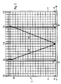
- the soundproofing wall 1 shown in the figures consists of five essentially U-shaped frames 2 to 6, each consisting of two long legs 7, 8, which are connected to one another in their upper region by a cross-member 9.
- the lower ends l0, ll of the long legs 7, 8 are attached to pins l2, l3, which are fixed at predetermined intervals on longitudinal members l4, l5 of a base frame, designated overall by l6.
- the side members consist in the embodiment of tubes, the inner diameter of which is somewhat larger than the diameter of the pins l2, l3.
- the upper cross members 9 are arranged slightly below the end of the long legs of the U-profiles 2 to 6. On this crossbar 9 of each U-shaped frame, a longitudinal crossbar l6 is attached, which is connected to all crossbars 9.
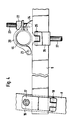
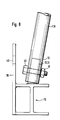
- Fig. 4 the section of the upper end of the soundproof wall 1 is shown in an enlarged view.
- the crossbar 9 is connected to the long legs 7, 8 by means of a clamp 17, which can be pivoted about a pivot bearing l8 and can be tightened by means of a screw l9.
- the longitudinal cross member 16 is attached to the cross member 9 with the same clamp 20.
- the clamp 20 is pivotable about a pivot bearing 2l and is clamped by means of a nut 22 which is screwed onto a threaded screw 23.
- connection piece 26 is pivotally fastened about a bearing 25, to which a tensioning cable 27 engages, the other end of which is fastened to the longitudinal member 14 or 15 of the base frame 16.
- Corrosion-protected structural steel mats 28, 29 are fastened to the side walls and also to the end walls of the soundproofing wall 1, which are either welded to the U-shaped frame parts 2 to 6 or are tied by means of corrosion-resistant wire.
- the surface facing upwards remains open, the soil filled into the soundproof wall 1 being trough-shaped in the upper region 30.
- the top opening can be used to simply refill soil to compensate for possible subsidence.
- the trough-shaped design has the advantage of better water absorption and accumulation and, moreover, an irrigation line can be arranged in this area within the soundproof wall 1, it being ensured during the irrigation that the water penetrates into the wall and does not run down to the side.
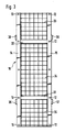
- the pedestal l6 is shown in plan view in FIG. 3. This consists of the two longitudinal beams 14, 15, which are connected to one another by cross beams 3l, 32. As shown in FIG. 1, the side members and also the cross members are made of a double-T profile of high strength. Corrosion-protected structural steel mats 32 to 35 are welded onto these longitudinal and cross members and carry the filled soil. If a relatively large mesh size is selected here, it is advantageous to additionally place a coconut mat on these structural steel mats. The same applies to the structural steel mats arranged on the sides and end walls.
- Four connecting points 36 to 39 are arranged on the longitudinal beams of the base frame l6, to which a lifting device can be connected, which lifts the soundproofing wall which has been assembled and filled with earth.
- a soundproofing wall according to FIGS. 1 to 4 is easily transportable and can be industrially prefabricated in the factory, filled with soil and planted before it is transported to its predetermined location. In this way, with cost-saving construction, the advantage is achieved that the remaining work on site is only for the preparation of the substrate and for the supply of a Supply line is limited.
- FIGS. 6 to 8 the same parts are provided with the same reference numerals.
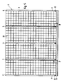
- the embodiment differs from that according to FIGS. 1 to 4 in that the upper longitudinal cross member 16 is missing.
- the rigidity is achieved in this embodiment in that the structural steel mats 28, 29 are welded directly to the legs 7, 8 of the U-shaped frames 2 to 6.
- Gusset plates 42 are welded to the legs 7, 8, on which the cross members 9 are fastened by means of screws 43.
- Fig. 8 the longitudinal beam 16 is shown, which consists of a double-T profile.
- the pins l2, l3, which have the same inclination as the legs 7, 8, are welded onto this longitudinal beam.
- the connection points 36 to 39 are welded to the side member, which have receiving holes 40 for the attack of the load hook of a lifting device, not shown.
- Each of the elements which are put together to form a planted noise barrier, has a length that allows them to be transported by truck on public roads and to be loaded and unloaded and erected using roadworthy heavy-duty cranes.
- the mats applied to the side walls of the elements advantageously consist of structural steel mats, the longitudinal bars of which are welded to the respective end frame parts.
- the middle frame parts of each element are not connected to the structural steel mat. This is only supported against these pipes.
- the gusset plates are welded, the spacing and dimensioning of which are selected according to the structural requirements.
- Prefabricated structural steel mats are fitted and fastened to the top of the elements. They should close the element body as lost formwork until it is installed at its final location.
- All structural steel mat surfaces such as the floor, side walls and end faces are lined with a vegetation mat or a suitable geotextile either before installation or after installation to prevent the filling material from trickling out. Then each element is filled with vegetation-friendly and soundproofing-favorable substrate. If the composition of the filler material - for example a strongly cohesive floor - fears the creation of a one-sided sliding joint, the resulting forces can be absorbed by installing diagonal struts or cables designed for tension and compression. The same applies if the noise barrier is to be filled on one side.
- the abutting elements are screwed together with their U-shaped frame parts. This compensates for the tensile forces that result from the backfill on the structural steel mesh from element to element.
Landscapes
- Engineering & Computer Science (AREA)
- Architecture (AREA)
- Civil Engineering (AREA)
- Structural Engineering (AREA)
- Devices Affording Protection Of Roads Or Walls For Sound Insulation (AREA)
- Cultivation Receptacles Or Flower-Pots, Or Pots For Seedlings (AREA)
- Revetment (AREA)
Abstract
Description
- Die Erfindung betrifft eine Schallschutzwand für Straßen und Plätze sowie für die gärtnerische Gestaltung, bestehend aus mehreren hintereinander und mit Abstand zueinander angeordneten, im wesentlichen U-förmigen Rahmen, die untereinander verbunden sind und auf deren Stirn- und Seitenflächen Matten aufgebracht sind. Derartige Schallschutzwände werden eingesetzt, um die Ausbreitung des Verkehrslärms zu mindern. Bekannt ist es hier, Lärmschutzwände aus Platten und Pfosten einzusetzen oder aber Lärmschutzwände in Form von geschütteten Dämmen und auch solche, bei denen die Lärmschutzwände ein inneres Gerüst haben, das mit Erde aufgefüllt ist und das anschließend bepflanzt wird. Die letzteren Lärmschutzwände haben den Vorteil, daß sie eine wesentlich geringere Grundfläche als Dämme benötigen.
- Die Herstellung derartiger Lärmschutzwände erfolgt in der Regel derart, daß zunächst ein Fundament erstellt wird, in dem die im wesentlichen U-förmigen Rahmenteile verankert werden. Diese U-förmigen Rahmenteile werden zur Abstützung gegeneinander mittels Traversen verbunden oder aber durch Spannseile gegeneinander abgestützt. Nach Aufstellung dieses Gerüstes werden dann auf das Gerüst Matten aus einem relativ engmaschigen Gewebe aufgebracht, die die Aufgabe haben, das Erdmaterial innerhalb der Schallschutzwand zu halten. Im Anschluß hieran wird dann die Wand bepflanzt. Dieser Arbeitsvorgang ist relativ zeitaufwendig, des weiteren kommt hinzu, daß die frisch aufgestellten Schallschutzwände auch innerhalb eines längeren Zeitraums nach dem Aufstellen noch keine Begrünung aufweisen.
- Der Erfindung liegt die Aufgabe zugrunde, eine Schallschutzwand der eingangs genannten Art so auszubilden, daß die Vorteile dieser Schallschutzwand beibehalten werden, daß jedoch die Baudauer und die Aufstellzeit der Schallschutzwand wesentlich verringert wird und es möglich ist, die Schallschutzwand bereits begrünt aufzustellen.
- Diese Aufgabe wird mit den Merkmalen des kennzeichnenden Teils des Anspruches l gelöst.
- Gemäß der Erfindung besteht somit die Schallschutzwand aus im wesentlichen U-förmig ausgebildeten Rahmenteilen, die untereinander über Matten und/oder Traversen verbunden sind und gegebenenfalls mittels Spannseilen untereinander versteift sind. Diese Rahmenteile sind auf einem starren Fußgestell befestigt, das so ausgebildet ist, daß dieses die gesamte Last der Schallschutzwand aufnehmen kann, so daß die Schallschutzwand mittels eines geeigneten Hebezeugs angehoben und transportiert werden kann. Eine derartige Schallschutzwand hat vorteilhaft eine Länge, mit der sie mit Lastwagen auf öffentlichen Straßen ohne Schwierigkeiten transportiert werden kann. Das Fußgestell besteht vorteilhaft aus zwei Längsträgern, die über zwei oder mehrere Querträger miteinander verbunden sind und an denen Befestigungsmittel für den Anschluß eines Hebegerätes angeordnet sind. Auf den Längsträgern sind vorteilhaft Zapfen angeordnet, die in die Enden der langen Schenkel der U-Profile eingesteckt werden. Hierdurch wird eine einfache und schnelle Montage der Schallschutzwand erhalten. Auf dem Fußgestell ist eine korrosionsgeschützte Baustahlmatte aufgebracht, auf der noch eine feinmaschige Matte aufgelegt sein kann, z.B. eine Kokosmatte, die ein Herausrieseln des Füllmaterials beim Transport verhindert. Eine gleiche Kokosmatte ist vorteilhaft unter den seitlichen und stirnseitig angeordneten Matten angeordnet, wobei diese Kokosmatten gleichzeitig mit Grassamen versetzt sein können, so daß hierdurch eine einheitliche Grundbegrünung erhalten wird.
- Schallschutzwände gemäß der Erfindung können im Herstellungsbetrieb vorgefertigt und bereits begrünt werden, so daß die für die eigentliche Aufstellung der Schallschutzwand benötigte Zeit vergleichweise sehr stark reduziert werden kann. Fundamente können eingespart werden.
- Weitere vorteilhafte Ausgestaltungen der Erfindung gehen aus den Unteransprüchen in Verbindung mit Zeichnung und Beschreibung hervor.
- Ein Ausführungsbeispiel ist im folgenden anhand der Zeichnung näher beschrieben, in dieser zeigen:
- Fig. l eine Stirnansicht eines erfindungsgemäß ausgebildeten Elementes einer Schallschutzwand,
- Fig. 2 eine Seitenansicht des in Fig. l gezeigten Elementes der Schallschutzwand,
- Fig. 3 eine Draufsicht auf das Fußgestell des Elementes einer Schallschutzwand nach Fig. l und 2,
- Fig. 4 die Befestigung der Verbindungsstreben an den U-Profilen des Elementes der Schallschutzwand nach Fig. l - 3,
- Fig. 5 eine Seitenansicht einer weiteren Ausführungsform eines Elementes einer Schallschutzwand,
- Fig. 6 eine Stirnansicht des in Fig. 5 gezeigten Elementes und
- Fig. 7 und 8 Details des Elementes nach den Fig. 5 und 6 in vergrößerter Darstellung.
- Die in den Figuren dargestellte Schallschutzwand l besteht aus fünf im wesentlichen U-förmigen Rahmen 2 bis 6, die je aus zwei langen Schenkeln 7, 8 bestehen, die in ihrem oberen Bereich durch eine Quertraverse 9 miteinander verbunden sind. Die unteren Enden l0, ll der langen Scshenkel 7, 8 sind auf Zapfen l2, l3 aufgesteckt, die in vorbestimmten Abständen auf Längsträgern l4, l5 eines insgesamt mit l6 bezeichneten Fußgestells befestigt sind. Die Längsträger bestehen im Ausführungsbeispiel aus Rohren, deren Innendurchmesser etwas größer ist als der Durchmesser der Zapfen l2, l3.
- Die oberen Quertraversen 9 sind etwas unterhalb des Endes der langen Schenkel der U-Profile 2 bis 6 angeordnet. Auf diesen Quertraversen 9 jedes U-förmigen Rahmens ist eine Längstraverse l6 befestigt, die mit sämtlichen Quertraversen 9 verbunden ist. In Fig. 4 ist der Ausschnitt des oberen Endes der Schallschutzwand l in vergrößerter Darstellung gezeigt. Die Quertraverse 9 ist mit den langen Schenkeln 7, 8 mittels einer Klemmschelle l7 verbunden, die um ein Drehlager l8 schwenkbar ist und mittels einer Schraube l9 festspannbar ist. Die Längstraverse l6 ist mit einer gleichen Klemmschelle 20 an der Quertraverse 9 befestigt. Die Klemmschelle 20 ist um ein Drehlager 2l schwenkbar und wird mittels einer Mutter 22, die auf einer Gewindeschraube 23 aufgeschraubt ist, verspannt. An dem an der Quertraverse 9 befestigten Teil 24 der Klemmschelle 20 ist schwenkbar um ein Lager 25 ein Anschlußstück 26 befestigt, an dem ein Spannseil 27 angreift, dessen anderes Ende am Längsträger l4 bzw. l5 des Fußgestells l6 befestigt ist. Auf die Seitenwände wie auch auf die Stirnwände der Schallschutzwand l sind korrosionsgeschütze Baustahlmatten 28, 29 befestigt, die entweder an den U-förmigen Rahmenteilen 2 bis 6 festgeschweißt oder aber mittels korrosionsbeständigem Draht festgebunden sind. Die nach oben weisende Fläche bleibt offen, wobei das in die Schallschutzwand l eingefüllte Erdreich im oberen Bereich 30 muldenförmig ausgebildet ist. Durch die obere Öffnung kann zum einen in einfacher Weise Erde nachgefüllt werden, um mögliche Setzungen auszugleichen. Darüber hinaus bietet die muldenförmige Ausbildung den Vorteil einer besseren Wasseraufnahme und -ansammlung und darüberhinaus kann in diesem Bereich innerhalb der Schallschutzwand l eine Bewässerungsleitung angeordnet werden, wobei bei der Bewässerung sichergestellt ist, daß das Wasser in die Wand eindringt und nicht seitlich herabläuft.
- Das Fußgestell l6 ist in Draufsicht in Fig. 3 dargestellt. Dies besteht aus den beiden Längersträgern l4, l5, die mit Querträgern 3l, 32 untereinander verbunden sind. Wie Fig. l zeigt, bestehen die Längsträger und auch die Querträger aus einem Doppel-T-Profil hoher Festigkeit. Auf diese Längs- und Querträger sind korrosionsgeschütze Baustahlmatten 32 bis 35 aufgeschweißt, die das eingefüllte Erdreich tragen. Wird hier eine relativ große Maschenweite gewählt, so ist es vorteilhaft, auf diese Baustahlmatten zusätzlich noch eine Kokosmatte aufzulegen. Das gleiche gilt für die an den Seiten und Stirnwänden angeordneten Baustahlmatten.
- An den Längsträgern des Fußgestells l6 sind vier Anschlußpunkte 36 bis 39 angeordnet, an denen ein Hebezeug anschließbar ist, das die fertig montierte und mit Erde gefüllte Schallschutzwand anhebt.
- Eine Schallschutzwand nach den Fig. l bis 4 ist leicht transportabel und kann industriell im Werk vorgefertigt, mit Erde gefüllt und begrünt werden, ehe diese an ihre vorbestimmte Stelle transportiert wird. Hierdurch wird bei kostensparender Bauweise der Vorteil erreicht, daß die verbleibenden Arbeiten vor Ort lediglich noch auf die Vorbereitung des Untergrundes wie auf die Zuführung einer evtl. Versorgungsleitung beschränkt ist.
- Bei den Ausführungsbeispielen nach Fig. 6 bis 8 sind gleiche Teile mit gleichen Bezugszeichen versehen. Das Ausführungsbeispiel unterscheidet sich von dem nach den Fig. l bis 4 dadurch, daß die obere Längstraverse l6 fehlt. Die Steifigkeit wird bei diesem Ausführungsbeispiel dadurch erreicht, daß die Baustahlmatten 28, 29 unmittelbar mit den Schenkeln 7, 8 der U-förmigen Rahmen 2 bis 6 verschweißt werden. Des weiteren ist bei diesem Ausführungsbeispiel nicht eine Quertraverse 9, sondern drei über die Höhe verteilt angeordnete Quertraversen vorgesehen, die die Steifigkeit des Elementes in Querrichtung wesentlich erhöhen. In Fig. 7 ist der Anschluß der Quertraverse 9 an den Schenkeln 7, 8 dargestellt. An den Schenkeln 7, 8 sind Knotenbleche 42 angeschweißt, an denen die Quertraversen 9 mittels Schrauben 43 befestigt sind.
- In Fig. 8 ist der Längsträger l6 dargestellt, der aus einem Doppel-T-Profil besteht. Auf diesen Längsträger sind die Zapfen l2, l3 angeschweißt, die die gleiche Neigung wie die Schenkel 7, 8 aufweisen. An den Längsträger sind die Anschlußpunkte 36 bis 39 angeschweißt, die Aufnahmebohrungen 40 für den Angriff der Lasthaken eines nicht dargestellten Hebezeuges haben.
- Jedes der Elemente, die zu einer bepflanzten Schallschutzwand zusammengestellt werden, hat eine Länge, die einen Transport mit Lastwagen auf öffentlichen Straßen und das Beund Entladen und Aufstellen mit straßentauglichen Schwerlastkränen erlaubt.
- Die auf den Seitenwänden der Elemente aufgebrachten Matten bestehen vorteilhaft aus Baustahlmatten, deren Längsstäbe mit den jeweiligen Endrahmenteilen verschweißt sind. Die mittleren Rahmenteile eines jeden Elementes sind nicht mit der Baustahlmatte verbunden. Diese stützt sich lediglich gegen diese Rohre ab. Auf der nach innen zeigenden Seite der U-förmigen Rahmenteile sind die Knotenbleche angeschweißt, die in Abstand und Dimensionierung jeweils nach dem statischen Erfordernis gewählt sind.
- An den Kopfseiten der Elemente werden vorgefertigte Baustahlmatten eingepaßt und befestigt. Sie sollen den Elementkörper als verlorene Schalung bis zur Aufstellung an seinem endgültigen Standort schließen.
- Alle Baustahlmattenflächen wie Boden, Seitenwände und Stirnflächen, werden entweder vor der Montage oder nach der Montage mit einer Vegetationsmatte oder einem geeigneten Geotextil ausgekleidet, um ein Herausrieseln des Füllmaterials zu vermeiden. Danach erfolgt die Füllung jedes Elementes mit vegetationsfreundlichem und schallschutztechnisch günstigem Substrat. Sollte die Zusammensetzung des Füllmaterials - z.B. stark bindiger Boden - das Entstehen einer einseitigen Gleitfuge befürchten lassen, so können die hierdurch auftretenden Kräfte durch den Einbau von auf Zug und Druck ausgelegten Diagonalstreben oder Seilen aufgenommen werden. Gleiches gilt, wenn die Lärmschutzwand einseitig angeschüttet werden soll.
- Nach der Aufstellung der einzelnen Elemente werden die aneinander anstoßenden Elemente mit ihren U-förmigen Rahmenteilen miteinander verschraubt. Hierdurch werden die Zugkräfte, die sich aus der Verfüllung auf das Baustahlgewebe ergeben, von Element zu Element ausgeglichen.
- Es ist auch denkbar, die Elemente mit einem kleinen Abstand zueinander anzuordnen und den Spalt zwischen diesen Elementen mit einer weiteren Baustahlmatte zu verschließen, die mit Seitenteilen ausgebildet sind, die um 90° abgewinkelt sind und die um die U-Profile benachbarter Elemente greifen. Diese Verkleidungsbaustahlelemente werden gleichfalls mit einer Vegetationsmatte versehen und werden dann vor Ort ausgefüllt. Aus optischen Gründen ist es darüberhinaus auch denkbar, jedes einzelne Rohrelement mit einer entsprechenden Matte zu verkleiden. Dies ist insbesondee im Anfangszustand der Vegetation vorteilhaft.
Claims (13)
Priority Applications (1)
| Application Number | Priority Date | Filing Date | Title |
|---|---|---|---|
| AT87104535T ATE53414T1 (de) | 1987-03-27 | 1987-03-27 | Schallschutzwand. |
Applications Claiming Priority (1)
| Application Number | Priority Date | Filing Date | Title |
|---|---|---|---|
| DE19853535343 DE3535343A1 (de) | 1985-10-03 | 1985-10-03 | Schallschutzwand |
Publications (2)
| Publication Number | Publication Date |
|---|---|
| EP0283542A1 true EP0283542A1 (de) | 1988-09-28 |
| EP0283542B1 EP0283542B1 (de) | 1990-06-06 |
Family
ID=6282687
Family Applications (1)
| Application Number | Title | Priority Date | Filing Date |
|---|---|---|---|
| EP87104535A Expired - Lifetime EP0283542B1 (de) | 1985-10-03 | 1987-03-27 | Schallschutzwand |
Country Status (3)
| Country | Link |
|---|---|
| US (1) | US4805734A (de) |
| EP (1) | EP0283542B1 (de) |
| DE (1) | DE3535343A1 (de) |
Families Citing this family (20)
| Publication number | Priority date | Publication date | Assignee | Title |
|---|---|---|---|---|
| DE3535343A1 (de) * | 1985-10-03 | 1987-04-09 | Mast Garten Landschaftsbau Kg | Schallschutzwand |
| EP0294778B1 (de) * | 1987-06-11 | 1992-04-01 | MAST Garten- und Landschaftsbau GmbH & Co. KG | Schutzwandelement |
| DE3719501A1 (de) * | 1987-06-11 | 1988-12-22 | Mast Garten Landschaftsbau Kg | Laermschutzwand |
| DE3933318A1 (de) * | 1989-10-05 | 1991-04-11 | August Dr Kuratko | Aus mehreren einzelnen bauelementen zusammengesetzte laerm- und oder staubschutzwand |
| IT1242073B (it) * | 1990-10-12 | 1994-02-08 | Comes Spa | Barriera fonoassorbente vegetativa. |
| US5450691A (en) * | 1993-05-11 | 1995-09-19 | Vermil Marketing Inc. | Support for plants and the like |
| GB0015660D0 (en) * | 2000-06-28 | 2000-08-16 | Speak William | Construction of walls |
| DE20113388U1 (de) | 2001-08-11 | 2001-10-18 | Vos, Martin de, 46397 Bocholt | Lärmschutzwand aus Zaunelementen |
| US7063184B1 (en) | 2002-06-12 | 2006-06-20 | Lahnie Johnson | Sound reducing panel |
| US8739924B2 (en) * | 2002-06-12 | 2014-06-03 | LJ Avalon LLC | Acoustic panel |
| US7503428B1 (en) | 2002-06-12 | 2009-03-17 | L.J. Avalon, L.L.C. | Acoustic panel |
| NL1022082C1 (nl) * | 2002-12-04 | 2003-02-04 | Henderik Booiman | Stelsel van bouwelementen en bouwelement als deel van dit stelsel. |
| US7513082B2 (en) * | 2004-02-09 | 2009-04-07 | Lahnie Johnson | Sound reducing system |
| ITBO20040380A1 (it) * | 2004-06-17 | 2004-09-17 | Euroambiente Srl | Struttura fonoassorbente inverdita |
| US20070131480A1 (en) * | 2004-12-06 | 2007-06-14 | Corbin Maxwell H Jr | Sound arresting barrier |
| EP2662491B1 (de) * | 2012-05-11 | 2014-03-26 | Jost Körte | Lärmschutzwand |
| US10526782B1 (en) | 2016-06-16 | 2020-01-07 | LJ Avalon LLC | Mobile carriage for acoustic panels |
| US10580396B1 (en) | 2017-04-07 | 2020-03-03 | The United States Of America As Represented By The Secretary Of The Navy | Acoustically stiff wall |
| DE102019105647A1 (de) * | 2019-03-06 | 2020-09-10 | Geosystem Gbk Gmbh | Trägersystem |
| US12173769B1 (en) * | 2021-04-28 | 2024-12-24 | LJ Avalon LLC | Vibration reducing system |
Citations (17)
| Publication number | Priority date | Publication date | Assignee | Title |
|---|---|---|---|---|
| US2113523A (en) * | 1937-08-18 | 1938-04-05 | White Stanley Hart | Vegetation-bearing architectonic structure and system |
| DE2744335A1 (de) * | 1977-10-01 | 1979-04-12 | Kesting Lorenz | Fertigteil aus stahlbeton fuer den aufbau von schutzwaellen zur laermbekaempfung des verkehrs, insbesondere des strassenverkehrs |
| DE2808486A1 (de) * | 1978-02-28 | 1979-08-30 | Wolf Begemann | Vegetative laermschutzwand |
| DE2848713A1 (de) * | 1978-11-09 | 1980-05-14 | Juergen Zapf | Laermschutzwand |
| DE3027442A1 (de) * | 1980-07-19 | 1982-02-11 | Wayss & Freytag Ag, 6000 Frankfurt | Schallschutzwand |
| DE3034131A1 (de) * | 1980-09-11 | 1982-04-01 | Lüft GmbH, 6501 Budenheim | Pflanzerdgeruest, insbesondere vegetative laermschutzwand |
| DE3144353A1 (de) * | 1981-05-06 | 1983-01-13 | Behrens, Wolfgang, 2833 Groß Ippener | Pflanzenkultur, insbesondere zum begruenen von schalldaemmwaenden |
| WO1984001791A1 (en) * | 1982-10-27 | 1984-05-10 | Henning Jensen | Plantwall usable as sound barrier |
| CH646221A5 (en) * | 1981-05-05 | 1984-11-15 | Walter Bischoff | Noise-reducing wall |
| EP0130178A2 (de) * | 1983-06-22 | 1985-01-02 | Sigisbert Bokan | Bauwerk für den Lärm-, Wind- oder Sichtschutz oder den Verbau von Ufern von Bächen und Flüssen |
| DE3328644A1 (de) * | 1983-08-08 | 1985-02-28 | Florakraft GmbH, 5101 Bergheim | Verfahren zum herstellen eines schallschutzbauwerkes aus muellkompost |
| DE3408207A1 (de) * | 1984-03-03 | 1985-09-05 | László Dr. 4300 Essen Czinki | Laermschutzmauer |
| DE8516306U1 (de) * | 1985-06-04 | 1985-12-19 | Mast, Garten- und Landschaftsbau KG, 6791 Niedermohr | Schallschutzwand |
| DE8531446U1 (de) * | 1985-11-07 | 1986-01-02 | Menzel, Hans-Claus, Dr., 7000 Stuttgart | Vegetationswand |
| EP0202552A1 (de) * | 1985-05-09 | 1986-11-26 | Lászlo Dr. Czinki | Raumelement aus Gittermatten |
| DE8618063U1 (de) * | 1986-07-05 | 1987-03-05 | Hansen, Volker, 27404 Heeslingen | Begrünbare Lärmschutzwand |
| DE3535343A1 (de) * | 1985-10-03 | 1987-04-09 | Mast Garten Landschaftsbau Kg | Schallschutzwand |
Family Cites Families (5)
| Publication number | Priority date | Publication date | Assignee | Title |
|---|---|---|---|---|
| DE7833360U1 (de) * | 1980-04-17 | Zapf, Juergen, 5800 Hagen | Lärmschutzwand | |
| US4065876A (en) * | 1976-08-02 | 1978-01-03 | Moffett Jr F Wesley | Portable garden and method of producing same |
| DE2744473C2 (de) * | 1977-10-03 | 1983-12-01 | Mamsero N.V., Curacao, Niederländische Antillen | Schutzvorrichtung, insbesondere Schallschutzeinrichtung und Böschungsbefestigung für Straßen |
| DE3043876A1 (de) * | 1980-11-21 | 1982-09-09 | Gustav 8820 Gunzenhausen Keller | Schallschutzwand |
| US4643271A (en) * | 1984-12-18 | 1987-02-17 | Thomas J. Kelley | Sound barrier |
-
1985
- 1985-10-03 DE DE19853535343 patent/DE3535343A1/de active Granted
-
1987
- 1987-03-27 EP EP87104535A patent/EP0283542B1/de not_active Expired - Lifetime
- 1987-04-02 US US07/034,123 patent/US4805734A/en not_active Expired - Fee Related
Patent Citations (17)
| Publication number | Priority date | Publication date | Assignee | Title |
|---|---|---|---|---|
| US2113523A (en) * | 1937-08-18 | 1938-04-05 | White Stanley Hart | Vegetation-bearing architectonic structure and system |
| DE2744335A1 (de) * | 1977-10-01 | 1979-04-12 | Kesting Lorenz | Fertigteil aus stahlbeton fuer den aufbau von schutzwaellen zur laermbekaempfung des verkehrs, insbesondere des strassenverkehrs |
| DE2808486A1 (de) * | 1978-02-28 | 1979-08-30 | Wolf Begemann | Vegetative laermschutzwand |
| DE2848713A1 (de) * | 1978-11-09 | 1980-05-14 | Juergen Zapf | Laermschutzwand |
| DE3027442A1 (de) * | 1980-07-19 | 1982-02-11 | Wayss & Freytag Ag, 6000 Frankfurt | Schallschutzwand |
| DE3034131A1 (de) * | 1980-09-11 | 1982-04-01 | Lüft GmbH, 6501 Budenheim | Pflanzerdgeruest, insbesondere vegetative laermschutzwand |
| CH646221A5 (en) * | 1981-05-05 | 1984-11-15 | Walter Bischoff | Noise-reducing wall |
| DE3144353A1 (de) * | 1981-05-06 | 1983-01-13 | Behrens, Wolfgang, 2833 Groß Ippener | Pflanzenkultur, insbesondere zum begruenen von schalldaemmwaenden |
| WO1984001791A1 (en) * | 1982-10-27 | 1984-05-10 | Henning Jensen | Plantwall usable as sound barrier |
| EP0130178A2 (de) * | 1983-06-22 | 1985-01-02 | Sigisbert Bokan | Bauwerk für den Lärm-, Wind- oder Sichtschutz oder den Verbau von Ufern von Bächen und Flüssen |
| DE3328644A1 (de) * | 1983-08-08 | 1985-02-28 | Florakraft GmbH, 5101 Bergheim | Verfahren zum herstellen eines schallschutzbauwerkes aus muellkompost |
| DE3408207A1 (de) * | 1984-03-03 | 1985-09-05 | László Dr. 4300 Essen Czinki | Laermschutzmauer |
| EP0202552A1 (de) * | 1985-05-09 | 1986-11-26 | Lászlo Dr. Czinki | Raumelement aus Gittermatten |
| DE8516306U1 (de) * | 1985-06-04 | 1985-12-19 | Mast, Garten- und Landschaftsbau KG, 6791 Niedermohr | Schallschutzwand |
| DE3535343A1 (de) * | 1985-10-03 | 1987-04-09 | Mast Garten Landschaftsbau Kg | Schallschutzwand |
| DE8531446U1 (de) * | 1985-11-07 | 1986-01-02 | Menzel, Hans-Claus, Dr., 7000 Stuttgart | Vegetationswand |
| DE8618063U1 (de) * | 1986-07-05 | 1987-03-05 | Hansen, Volker, 27404 Heeslingen | Begrünbare Lärmschutzwand |
Also Published As
| Publication number | Publication date |
|---|---|
| US4805734A (en) | 1989-02-21 |
| EP0283542B1 (de) | 1990-06-06 |
| DE3535343C2 (de) | 1988-08-18 |
| DE3535343A1 (de) | 1987-04-09 |
Similar Documents
| Publication | Publication Date | Title |
|---|---|---|
| EP0283542B1 (de) | Schallschutzwand | |
| DE3504133A1 (de) | Sonnen- und wetterschutzanlage, insbesondere zur ueberdachung groesserer grundflaechen | |
| EP0202552B1 (de) | Raumelement aus Gittermatten | |
| DE2109088C3 (de) | Räumliches Bauelement zur Bildung von bezüglich ihrer Ausdehnung ein Vielfaches der größten Kantenlänge des Bauelementes aufweisenden, auf Biegung beanspruchbaren Trag- und Stützwerken | |
| DE9107201U1 (de) | Schalung zum Betonieren von Kappen oder Gesimsen an einem langgestreckten Bauwerk, vorzugsweise einer Brücke | |
| DE2361133A1 (de) | Geruestkran | |
| DE2556365C2 (de) | Stützenturm | |
| EP0004251A1 (de) | Verfahren zur Herstellung eines tragenden Bauwerkes, Einrichtung zur Durchführung dieses Verfahrens und Bausatz zur Erstellung der Einrichtung | |
| DE9103220U1 (de) | Lärmschutz- und Hangstützwand aus Drahtgittermatten | |
| DE10109811A1 (de) | Dachgebinde mit höhenverstellbarem Pfosten | |
| DE3406748C2 (de) | ||
| EP0682730B1 (de) | Haus aus fertigbauelementen | |
| DE3203980C2 (de) | Unterführungsbauwerk sowie Verfahren zu seiner Herstellung | |
| DE2854624C2 (de) | Gerüst zur Halterung von Geräten | |
| DE3333743A1 (de) | Vorrichtung zum abstuetzen einer erdsteilwand | |
| EP0294778B1 (de) | Schutzwandelement | |
| DE1684213B2 (de) | Gebäude mit aus Einzelteilen gefertigten Rahmen | |
| DE8618063U1 (de) | Begrünbare Lärmschutzwand | |
| DE8030003U1 (de) | Bauelementensatz zum verankern von boeschungsstuetzwaenden u.dgl. | |
| DE2614186A1 (de) | Vorgefertigte schalung zur herstellung von ringankern an bauwerken | |
| AT139156B (de) | Fundament für Straßen, Höfe, Flugzeugstationen und ähnliche Oberflächen. | |
| CH620490A5 (en) | Supporting structure for a shuttering | |
| CH666930A5 (de) | Armierung fuer betonmauern. | |
| DE2257367A1 (de) | Bahnsteigkanten-laengsabschnitt | |
| DE1409373A1 (de) | Einstellbares Teleskopgeruest |
Legal Events
| Date | Code | Title | Description |
|---|---|---|---|
| PUAI | Public reference made under article 153(3) epc to a published international application that has entered the european phase |
Free format text: ORIGINAL CODE: 0009012 |
|
| 17P | Request for examination filed |
Effective date: 19880503 |
|
| AK | Designated contracting states |
Kind code of ref document: A1 Designated state(s): AT BE CH IT LI NL SE |
|
| 17Q | First examination report despatched |
Effective date: 19881209 |
|
| GRAA | (expected) grant |
Free format text: ORIGINAL CODE: 0009210 |
|
| AK | Designated contracting states |
Kind code of ref document: B1 Designated state(s): AT BE CH IT LI NL SE |
|
| ITF | It: translation for a ep patent filed | ||
| REF | Corresponds to: |
Ref document number: 53414 Country of ref document: AT Date of ref document: 19900615 Kind code of ref document: T |
|
| PGFP | Annual fee paid to national office [announced via postgrant information from national office to epo] |
Ref country code: CH Payment date: 19910319 Year of fee payment: 5 |
|
| PGFP | Annual fee paid to national office [announced via postgrant information from national office to epo] |
Ref country code: AT Payment date: 19910326 Year of fee payment: 5 |
|
| PLBE | No opposition filed within time limit |
Free format text: ORIGINAL CODE: 0009261 |
|
| STAA | Information on the status of an ep patent application or granted ep patent |
Free format text: STATUS: NO OPPOSITION FILED WITHIN TIME LIMIT |
|
| ITTA | It: last paid annual fee | ||
| PG25 | Lapsed in a contracting state [announced via postgrant information from national office to epo] |
Ref country code: BE Effective date: 19910331 |
|
| PGFP | Annual fee paid to national office [announced via postgrant information from national office to epo] |
Ref country code: NL Payment date: 19910331 Year of fee payment: 5 |
|
| 26N | No opposition filed | ||
| BERE | Be: lapsed |
Owner name: MAST GARTEN- UND LANDSCHAFTSBAU K.G. Effective date: 19910331 |
|
| PG25 | Lapsed in a contracting state [announced via postgrant information from national office to epo] |
Ref country code: AT Effective date: 19920327 |
|
| PG25 | Lapsed in a contracting state [announced via postgrant information from national office to epo] |
Ref country code: LI Effective date: 19920331 Ref country code: CH Effective date: 19920331 |
|
| PG25 | Lapsed in a contracting state [announced via postgrant information from national office to epo] |
Ref country code: NL Effective date: 19921001 |
|
| NLV4 | Nl: lapsed or anulled due to non-payment of the annual fee | ||
| REG | Reference to a national code |
Ref country code: CH Ref legal event code: PL |
|
| EAL | Se: european patent in force in sweden |
Ref document number: 87104535.7 |
|
| PGFP | Annual fee paid to national office [announced via postgrant information from national office to epo] |
Ref country code: SE Payment date: 19960321 Year of fee payment: 10 |
|
| PG25 | Lapsed in a contracting state [announced via postgrant information from national office to epo] |
Ref country code: SE Effective date: 19970328 |
|
| EUG | Se: european patent has lapsed |
Ref document number: 87104535.7 |
|
| PG25 | Lapsed in a contracting state [announced via postgrant information from national office to epo] |
Ref country code: IT Free format text: LAPSE BECAUSE OF NON-PAYMENT OF DUE FEES;WARNING: LAPSES OF ITALIAN PATENTS WITH EFFECTIVE DATE BEFORE 2007 MAY HAVE OCCURRED AT ANY TIME BEFORE 2007. THE CORRECT EFFECTIVE DATE MAY BE DIFFERENT FROM THE ONE RECORDED. Effective date: 20050327 |