EP0283619A2 - Support de présentation conditionné et méthode d'érection - Google Patents
Support de présentation conditionné et méthode d'érection Download PDFInfo
- Publication number
- EP0283619A2 EP0283619A2 EP87306890A EP87306890A EP0283619A2 EP 0283619 A2 EP0283619 A2 EP 0283619A2 EP 87306890 A EP87306890 A EP 87306890A EP 87306890 A EP87306890 A EP 87306890A EP 0283619 A2 EP0283619 A2 EP 0283619A2
- Authority
- EP
- European Patent Office
- Prior art keywords
- base
- tray
- panels
- display stand
- condition
- Prior art date
- Legal status (The legal status is an assumption and is not a legal conclusion. Google has not performed a legal analysis and makes no representation as to the accuracy of the status listed.)
- Granted
Links
Images

Classifications
-
- A—HUMAN NECESSITIES
- A47—FURNITURE; DOMESTIC ARTICLES OR APPLIANCES; COFFEE MILLS; SPICE MILLS; SUCTION CLEANERS IN GENERAL
- A47F—SPECIAL FURNITURE, FITTINGS, OR ACCESSORIES FOR SHOPS, STOREHOUSES, BARS, RESTAURANTS OR THE LIKE; PAYING COUNTERS
- A47F1/00—Racks for dispensing merchandise; Containers for dispensing merchandise
- A47F1/02—Racks for dispensing merchandise; Containers for dispensing merchandise for granulated or powdered materials, i.e. bulk materials
-
- A—HUMAN NECESSITIES
- A47—FURNITURE; DOMESTIC ARTICLES OR APPLIANCES; COFFEE MILLS; SPICE MILLS; SUCTION CLEANERS IN GENERAL
- A47F—SPECIAL FURNITURE, FITTINGS, OR ACCESSORIES FOR SHOPS, STOREHOUSES, BARS, RESTAURANTS OR THE LIKE; PAYING COUNTERS
- A47F5/00—Show stands, hangers, or shelves characterised by their constructional features
- A47F5/10—Adjustable or foldable or dismountable display stands
- A47F5/11—Adjustable or foldable or dismountable display stands made of cardboard, paper or the like
- A47F5/112—Adjustable or foldable or dismountable display stands made of cardboard, paper or the like hand-folded from sheet material
- A47F5/114—Adjustable or foldable or dismountable display stands made of cardboard, paper or the like hand-folded from sheet material in the form of trays with a base
Definitions
- This invention generally relates to a pre-pack display stand and, more particularly, to a method of erecting the same.
- Pre-pack display stands are known in which a tray is packed in advance with articles to be displayed.
- a discrete stand is typically erected in situ at a retail establishment. Thereupon, the pre-pack tray is placed on the erected stand in order to display the articles contained therein.
- the known pre-pack display stands possess many disadvantages.
- the stand and the tray are separate items, they are prone to being misplaced or lost. They also must be separately inventoried, shipped and paired together at the retail establishment. In addition, the tray can fall off the stand, thereby spilling the articles.
- Yet another object of this invention is to prevent the misplacement and/or loss of the tray and/or the stand.
- Still another object of this invention is to reduce the time spent and skill involved in erecting a pre-pack display stand.
- a display stand comprising a pre-pack tray in which articles to be displayed are packed, and a base erectable from a collapsed to an erect condition.
- the tray is connected to the base for movement among a compact storage position in which the tray rests on and maintains the base in the collapsed condition, a lifted position in which the tray is raised above the base, and a lowered position in which the tray is lowered onto the base in the erect condition.
- the base is automatically erected to the erect condition in the lifted position of the tray.
- Means are provided on the base for supporting the tray thereon in the lowered position of the tray.
- the pre-pack display stand is erected in the following manner:
- the pre-pack tray is lifted from the base in the collapsed position in which the tray maintained the base.
- the base is automatically erected while the tray is lifted above the base.
- the tray is lowered onto the base, whereupon the erected base supports the tray.
- the pre-pack stand of this invention is automatically, quickly and efficiently erected.
- the time spent and the skill involved in erecting the stand are at a minimum. It is no longer necessary to separately inventory, ship or match separate trays and stands, since, as stated above, the tray and stand of this invention are interconnected, preferably by a hinge panel.
- the base has front and rear panels lying substantially flat against each other in the collapsed condition, and movable away from each other in mutual parallelism during erection of the base to the erect condition.
- the base also has side panels extending between the front and rear panels at opposite sides of the stand. Each side panel has a pair of side panel portions which lie substantially flat against each other in the collapsed condition, and which are out-folded into a coplanar state during erection of the base.
- a pair of support panels are provided on the base, the support panels being movable toward each other into a common plane during erection of the base. Means are provided for constantly biasing the support panels toward each other.
- a circumferentially complete elastomeric band has opposite arcuate ends received in respective slots formed in the support panels.
- the band In the collapsed condition, the band is stretched to a high-tensioned state. In the erect condition, the band is returned to a less-tensioned state. All of the aforementioned panels are flat and juxtaposed with one another in the collapsed condition.
- the tray is advantageously provided with a flat-bottom panel lying substantially flat against the flattened panels of the base in the collapsed condition.
- the support panels have first upper support surfaces.
- the front, rear and side panels have second upper support surfaces which, together with the first upper support surfaces, substantially lie in a support plane on which the flat-bottom panel of the tray support severelyably rests.
- the tray has a front border panel, as well as rear and side border panels, each extending generally normally of the bottom panel thereof.
- the side panels of the base have notches in which the front border and bottom panels of the tray are at least partially supportably received.
- a locking flap may be provided on and extend above the front panel. The locking flap engages the front border panel and assists in preventing the tray from falling off the base.
- the tray is connected to the base by connecting means, including a hinge flap or panel.
- the hinge flap has one hinge section secured to the base, and an opposite hinge section secured to the bottom panel of the tray. These hinge sections are pivotable relative to each other about a hinge axis among the aforementioned tray positions.
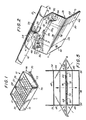
- reference numeral 10 generally identifies a pre-pack display stand, shown in a fully-collapsed condition in FIG. 1, and in a fully-erect condition in FIG. 4.
- the FIG. 4 condition shows the stand in its intended position of use, wherein articles 12, shown for the sake of simplicity as balls, are on display.
- the display stand 10 is shown in two intermediate conditions in FIGs. 2 and 3 during the course of erecting the stand.
- the stand 10 includes a tray 14 having a flat bottom panel 16, a front border panel 18, a rear border panel 20, and two side border panels 22, 24.
- the border panels each extend perpendicularly of the bottom panel 16, and together form a rectangular border surrounding the entire perimeter of bottom panel 16.
- the articles 12 are placed on bottom panel 16 and confined in the tray by the border panels.
- Partition panels 26, 28 subdivide the interior of the tray for sorting the articles.
- Stand 10 also includes a base 30 erectable from a collapsed to an erect condition.
- the tray 14 is pivotably connected to the base 30 by means of a hinge panel or flap 32 having one hinge section 34 fixedly secured, e.g. by glueing or stapling, to the bottom tray panel 16, and another hinge section 36 similarly fixedly secured to the base 30.
- the hinge sections 34, 36 are angularly movable in a circumferential direction about hinge axis A-A which extends along a fold line of the hinge 32.
- the tray 14 is pivotable upwardly, and is lifted manually above the base (see FIG. 2), and is pivotable downwardly and lowered onto the base (see FIG. 3).
- the base 30 includes a front panel 38 and a rear panel 40 lying substantially flat against each other in the collapsed condition (FIG.1), and movable away from each other in mutual parallelism during erection of the base to the erect condition (FIG. 3).
- the base 30 also includes side panels extending between the front and rear panels at opposite sides of the stand.
- Each side panel includes a pair of side panel portions 42, 44 and 46, 48.
- Each side panel portion pair lies substantially flat against each other in the collapsed condition, and are out-folded from each other in a coplanar state during erection of the base.
- the coplanar side panel portions 42, 44 extend generally parallel to the coplanar side panel portions 46, 48.
- Front panel 38 is hinged to side panel portions 42, 46 along fold lines 50, 52.
- Rear panel 40 is hinged to side panel portions 44, 48 along fold lines 54, 56.
- Side panel portions 42, 44 meet and are foldable about upright fold line 58.
- Side panel portions 46, 48 meet and are foldable about upright fold line 60.
- the fold lines 58, 60 lie in a common plane B-B.
- the front and rear panels are movable toward and away from said common plane B-B with concomitant folding of the side panels onto each other, and unfolding of the side panels into respective coplanar states, respectively.
- a pair of support panels each constituted of a pair of support panel portions 62, 64 and 66, 68, are hinged to side panel portions 42, 44 and 46, 48, respectively (see FIG. 5).
- Support panel portions 62, 64 are coplanar with support panel portions 66, 68, and lie in the common plane B-B.
- Support panel portions 62, 64 are located further apart from support panel portions 66, 68 in the collapsed condition, and are moved closer to support panel portions 66, 68 in the erect condition.
- Slots 70 are formed through upper marginal portions of support panel portions 62, 64. Slots 72 are formed through upper marginal portions of support panel portions 66, 68.
- a circumferentially complete elastomeric band 74 preferably a rubber band, has opposite arcuate ends frictionally received and maintained in slots 70, 72.
- Band 74 is stretchable between a high-tensioned stretched state in the collapsed condition wherein the support panel portion pairs 62, 64 and 66, 68 are spaced apart, and a less-tensioned state in the erect condition wherein the support panel portion pairs are located closer together. The energy stored in the stretched band 74 constantly urges the support panel portion pairs together.
- the band 74 serves as a biasing means operative for urging the support panel portion pairs together and, in turn, to unfold the side panel portion pairs to their respective coplanar states wherein the side panels are in mutual parallelism.
- the biasing means moves the front and rear panels away from each other until the erect condition of the base shown in FIGs. 3 and 4 is obtained.
- the outside holding force could be provided by non-illustrated clamping or similar holding means.
- the base 30 can be provided with a transverse fold line or crease 76 which divides the base into an upper part and a lower part.
- the weight of the tray, as well as the weight of the articles packed therein, acting in the direction of arrow C in FIG. 1, is sufficient to maintain the base in the illustrated compact storage position shown in FIG. 1 without risk that the base 30 will automatically pop open and erect itself under the influence of the biasing means.
- the pre-pack tray with the base folded flat underneath the same is shipped in the orientation shown in FIG. 1 to a display site.
- a display site Once it is desired to erect a display stand at the display site, it is merely necessary to manually lift the tray 14 up above the folded base 30.
- the base 30 By removing the downwardly directed force acting to maintain the base in the collapsed condition, the base 30 is free to erect itself by unfolding and deploying the panels under the biasing action of the band 74 which acts in the directions of arrows D in FIG. 2.
- the base 30 having been fully erected, the tray 14 may now be lowered in the direction of arrow E in FIG. 3 onto the erected base.
- the tray is automatically centered on the base.
- the tray cannot be mounted off-center or laterally shifted on the base due, primarily, to the hinge panel 32.
- Each of the base panels has an upper edge or support surface on which the tray is supported.
- front panels 38, 40 have upper support surfaces 38 a , 40 a .
- Side panel portions 42, 44, 46, 48 have upper support surfaces 42 a , 44 a , 46 a , 48 a , respectively. All of the aforementioned support surfaces bound a four-sided support on which the tray can be reliably supported from below without tipping either in the front-to-back or side-to-side directions.
- the support panels have upper support surfaces 80, 82 which advantageously may contact the bottom panel 16 of the tray and help support the same across its middle.
- upper support surfaces 42 a , 46 a can be notched at 84, 86 in order to engage the front border panel 18 at opposite lateral end regions thereof and to engage, at least in part, the bottom panel 16. Still further, not only is the back of the tray held in position by hinge panel 32 and thereby prevented from sliding downwardly or falling off the base, but, also, the front of the tray is held in position by a locking flap 88 of one piece with and extending above the upper support surface 38 a of the front panel 38. The locking flap 88 engages the front border panel 18 and effectively locks the tray in place, a situation best shown in FIG. 4.
- the upper support surfaces of the base are inclined relative to the horizontal so that the tray itself is supported on an incline. The angle of inclination of the tray is advantageously chosen to provide maximum eye-catching appeal for the articles on display.
- the tray itself, as well as the display stand, may be constituted of cardboard or corrugated board.
Landscapes
- Display Racks (AREA)
- Cartons (AREA)
Applications Claiming Priority (2)
| Application Number | Priority Date | Filing Date | Title |
|---|---|---|---|
| US07/031,024 US4726476A (en) | 1987-03-27 | 1987-03-27 | Pre-pack display stand and method of erection |
| US31024 | 1987-03-27 |
Publications (3)
| Publication Number | Publication Date |
|---|---|
| EP0283619A2 true EP0283619A2 (fr) | 1988-09-28 |
| EP0283619A3 EP0283619A3 (en) | 1989-10-18 |
| EP0283619B1 EP0283619B1 (fr) | 1992-10-07 |
Family
ID=21857250
Family Applications (1)
| Application Number | Title | Priority Date | Filing Date |
|---|---|---|---|
| EP87306890A Expired - Lifetime EP0283619B1 (fr) | 1987-03-27 | 1987-08-04 | Support de présentation conditionné et méthode d'érection |
Country Status (7)
| Country | Link |
|---|---|
| US (1) | US4726476A (fr) |
| EP (1) | EP0283619B1 (fr) |
| JP (2) | JPS63252107A (fr) |
| KR (1) | KR880010722A (fr) |
| AU (1) | AU572421B1 (fr) |
| CA (1) | CA1284476C (fr) |
| DE (1) | DE3782163T2 (fr) |
Cited By (2)
| Publication number | Priority date | Publication date | Assignee | Title |
|---|---|---|---|---|
| EP0340680A3 (fr) * | 1988-05-02 | 1990-07-04 | Paul Mühl | Présentoir |
| WO2005004677A1 (fr) * | 2003-07-10 | 2005-01-20 | Geoffrey Alan Moss | Presentoir a base de soutien pliable autodepliante |
Families Citing this family (15)
| Publication number | Priority date | Publication date | Assignee | Title |
|---|---|---|---|---|
| US4938343A (en) * | 1987-07-13 | 1990-07-03 | Willis William T | Preassembled display stand and container assembly |
| US4991804A (en) * | 1989-11-27 | 1991-02-12 | Steve Iannucci | Display stand |
| US5161699A (en) * | 1992-04-13 | 1992-11-10 | The Mead Corporation | Display stand having stair-like multiple box structure |
| USD351516S (en) | 1992-08-10 | 1994-10-18 | John Yeh | Article display structure |
| ES2063665B1 (es) * | 1992-12-03 | 1998-01-16 | Miralles Cartonajes | Caja expositor desplegable. |
| US5443168A (en) * | 1994-01-05 | 1995-08-22 | Dyment Limited | Portable display stand with shelves |
| US5555975A (en) * | 1994-11-15 | 1996-09-17 | Arrow Art Finishers, Inc. | Shipping container convertible into display stand |
| US5547073A (en) * | 1994-12-05 | 1996-08-20 | Arrow Art Finishers, Inc. | Display stand erectable from shipping container |
| FR2769819B1 (fr) * | 1997-10-20 | 1999-12-24 | Yves Hetroy | Plateau de presentation |
| US6918491B2 (en) * | 2003-07-10 | 2005-07-19 | Geoffrey Alan Moss | Display stand with foldable self erecting supporting base |
| US20060213150A1 (en) * | 2005-03-24 | 2006-09-28 | Sonon James A | Method for product handling using a configurable display container |
| US7520390B2 (en) | 2005-03-24 | 2009-04-21 | The Kroger Co. | Configurable display container |
| US7588404B2 (en) | 2005-03-24 | 2009-09-15 | The Kroger Co. | Container handling apparatus and container |
| CN109982611B (zh) * | 2016-11-21 | 2022-03-22 | Wm.雷格利 Jr.公司 | 产品展示架 |
| US20210298493A1 (en) * | 2020-03-30 | 2021-09-30 | Menasha Corporation | Ship flat hutch |
Family Cites Families (10)
| Publication number | Priority date | Publication date | Assignee | Title |
|---|---|---|---|---|
| US3836104A (en) * | 1973-04-12 | 1974-09-17 | Container Corp | Display stand |
| AT343714B (de) * | 1974-08-14 | 1978-06-12 | Plasser Bahnbaumasch Franz | Forderkette fur gleisbaumaschinen mit kettenspannvorrichtung |
| US4579220A (en) * | 1981-09-08 | 1986-04-01 | Champion International Corporation | Shipping and display container |
| US4493424A (en) * | 1981-10-09 | 1985-01-15 | Irving Smith | Foldable display stand |
| US4411382A (en) * | 1982-06-21 | 1983-10-25 | Taub Ronald H | Erectable display assembly with self-contained pacakged product |
| DE8222484U1 (de) * | 1982-08-09 | 1982-12-02 | Schröter + Bake GmbH + Co KG Werke für moderne Verpackung, 8402 Neutraubling | Bodenaufsteller |
| DE8323978U1 (de) * | 1983-08-20 | 1983-11-17 | Gustav Stabernack Gmbh, 6420 Lauterbach | Aus Faltmaterial hergestellter Bodenaufsteller |
| DE8330781U1 (de) * | 1983-10-27 | 1984-01-26 | Gustav Stabernack Gmbh, 6420 Lauterbach | Bodenaufsteller |
| DE8409845U1 (de) * | 1984-03-30 | 1984-05-24 | Gustav Stabernack Gmbh, 6420 Lauterbach | Bodenaufsteller aus faltmaterial |
| CA1225370A (fr) * | 1984-10-22 | 1987-08-11 | Irving Smith | Presentoir pliant |
-
1987
- 1987-03-27 US US07/031,024 patent/US4726476A/en not_active Expired - Lifetime
- 1987-08-03 AU AU76529/87A patent/AU572421B1/en not_active Ceased
- 1987-08-04 EP EP87306890A patent/EP0283619B1/fr not_active Expired - Lifetime
- 1987-08-04 DE DE8787306890T patent/DE3782163T2/de not_active Expired - Fee Related
- 1987-08-24 KR KR870009246A patent/KR880010722A/ko not_active Withdrawn
- 1987-08-28 JP JP62216260A patent/JPS63252107A/ja active Pending
- 1987-10-01 CA CA000548350A patent/CA1284476C/fr not_active Expired - Fee Related
-
1994
- 1994-09-29 JP JP013211U patent/JPH0725868U/ja active Pending
Cited By (2)
| Publication number | Priority date | Publication date | Assignee | Title |
|---|---|---|---|---|
| EP0340680A3 (fr) * | 1988-05-02 | 1990-07-04 | Paul Mühl | Présentoir |
| WO2005004677A1 (fr) * | 2003-07-10 | 2005-01-20 | Geoffrey Alan Moss | Presentoir a base de soutien pliable autodepliante |
Also Published As
| Publication number | Publication date |
|---|---|
| CA1284476C (fr) | 1991-05-28 |
| EP0283619A3 (en) | 1989-10-18 |
| DE3782163D1 (de) | 1992-11-12 |
| JPS63252107A (ja) | 1988-10-19 |
| DE3782163T2 (de) | 1993-02-11 |
| US4726476A (en) | 1988-02-23 |
| KR880010722A (ko) | 1988-10-24 |
| AU572421B1 (en) | 1988-05-05 |
| EP0283619B1 (fr) | 1992-10-07 |
| JPH0725868U (ja) | 1995-05-16 |
Similar Documents
| Publication | Publication Date | Title |
|---|---|---|
| US4726476A (en) | Pre-pack display stand and method of erection | |
| US4723664A (en) | Reinforced display stand for supporting heavy loads | |
| US4582003A (en) | Folding corrugated board display shelving | |
| USRE32668E (en) | Foldable display stand | |
| US6098820A (en) | Tipping-resistant display stand | |
| US5315936A (en) | Erectable display stand | |
| US5322172A (en) | Collapsible display stand | |
| US6158361A (en) | Foldable table frame | |
| US4570805A (en) | Foldable display stand | |
| US8136678B2 (en) | Merchandise display support stand | |
| US7753218B2 (en) | Tilt back merchandise display stand | |
| US4725028A (en) | Collapsible/expandable trivet | |
| US4519318A (en) | Collapsible support structures | |
| US7070057B2 (en) | Foldable display stand with self erecting stabilizing base | |
| US3008463A (en) | Combined barbecue grill and hand truck | |
| US4122782A (en) | Folding shelving | |
| ZA200202891B (en) | A folding assembly. | |
| US5657703A (en) | Portable work station | |
| US20120267329A1 (en) | Auto-adjustable position exhibitor | |
| US5535847A (en) | Table top attachment for sawhorses | |
| US6338216B1 (en) | Interlocking crossbar easel | |
| US20060076003A1 (en) | Foldable camping grill | |
| WO2008085534A1 (fr) | Gril portable et pré-assemblé à système de pieds escamotables | |
| US6918491B2 (en) | Display stand with foldable self erecting supporting base | |
| US1895535A (en) | Display rack or stand |
Legal Events
| Date | Code | Title | Description |
|---|---|---|---|
| PUAI | Public reference made under article 153(3) epc to a published international application that has entered the european phase |
Free format text: ORIGINAL CODE: 0009012 |
|
| 17P | Request for examination filed |
Effective date: 19871207 |
|
| AK | Designated contracting states |
Kind code of ref document: A2 Designated state(s): BE DE FR GB IT LU NL |
|
| PUAL | Search report despatched |
Free format text: ORIGINAL CODE: 0009013 |
|
| AK | Designated contracting states |
Kind code of ref document: A3 Designated state(s): BE DE FR GB IT LU NL |
|
| 17Q | First examination report despatched |
Effective date: 19910403 |
|
| GRAA | (expected) grant |
Free format text: ORIGINAL CODE: 0009210 |
|
| AK | Designated contracting states |
Kind code of ref document: B1 Designated state(s): BE DE FR GB IT LU NL |
|
| ITF | It: translation for a ep patent filed | ||
| REF | Corresponds to: |
Ref document number: 3782163 Country of ref document: DE Date of ref document: 19921112 |
|
| ET | Fr: translation filed | ||
| PLBE | No opposition filed within time limit |
Free format text: ORIGINAL CODE: 0009261 |
|
| STAA | Information on the status of an ep patent application or granted ep patent |
Free format text: STATUS: NO OPPOSITION FILED WITHIN TIME LIMIT |
|
| 26N | No opposition filed | ||
| EPTA | Lu: last paid annual fee | ||
| PGFP | Annual fee paid to national office [announced via postgrant information from national office to epo] |
Ref country code: GB Payment date: 19950724 Year of fee payment: 9 |
|
| PGFP | Annual fee paid to national office [announced via postgrant information from national office to epo] |
Ref country code: FR Payment date: 19950809 Year of fee payment: 9 Ref country code: DE Payment date: 19950809 Year of fee payment: 9 |
|
| PGFP | Annual fee paid to national office [announced via postgrant information from national office to epo] |
Ref country code: NL Payment date: 19950825 Year of fee payment: 9 |
|
| PGFP | Annual fee paid to national office [announced via postgrant information from national office to epo] |
Ref country code: BE Payment date: 19950911 Year of fee payment: 9 |
|
| PGFP | Annual fee paid to national office [announced via postgrant information from national office to epo] |
Ref country code: LU Payment date: 19951001 Year of fee payment: 9 |
|
| PG25 | Lapsed in a contracting state [announced via postgrant information from national office to epo] |
Ref country code: LU Free format text: LAPSE BECAUSE OF NON-PAYMENT OF DUE FEES Effective date: 19960804 Ref country code: GB Effective date: 19960804 |
|
| PG25 | Lapsed in a contracting state [announced via postgrant information from national office to epo] |
Ref country code: BE Effective date: 19960831 |
|
| BERE | Be: lapsed |
Owner name: ARROW ART FINISHERS CO Effective date: 19960831 |
|
| PG25 | Lapsed in a contracting state [announced via postgrant information from national office to epo] |
Ref country code: NL Effective date: 19970301 |
|
| GBPC | Gb: european patent ceased through non-payment of renewal fee |
Effective date: 19960804 |
|
| PG25 | Lapsed in a contracting state [announced via postgrant information from national office to epo] |
Ref country code: FR Effective date: 19970430 |
|
| NLV4 | Nl: lapsed or anulled due to non-payment of the annual fee |
Effective date: 19970301 |
|
| PG25 | Lapsed in a contracting state [announced via postgrant information from national office to epo] |
Ref country code: DE Effective date: 19970501 |
|
| REG | Reference to a national code |
Ref country code: FR Ref legal event code: ST |
|
| PG25 | Lapsed in a contracting state [announced via postgrant information from national office to epo] |
Ref country code: IT Free format text: LAPSE BECAUSE OF NON-PAYMENT OF DUE FEES;WARNING: LAPSES OF ITALIAN PATENTS WITH EFFECTIVE DATE BEFORE 2007 MAY HAVE OCCURRED AT ANY TIME BEFORE 2007. THE CORRECT EFFECTIVE DATE MAY BE DIFFERENT FROM THE ONE RECORDED. Effective date: 20050804 |