EP0283633A2 - Heizungsanlage - Google Patents
Heizungsanlage Download PDFInfo
- Publication number
- EP0283633A2 EP0283633A2 EP87830269A EP87830269A EP0283633A2 EP 0283633 A2 EP0283633 A2 EP 0283633A2 EP 87830269 A EP87830269 A EP 87830269A EP 87830269 A EP87830269 A EP 87830269A EP 0283633 A2 EP0283633 A2 EP 0283633A2
- Authority
- EP
- European Patent Office
- Prior art keywords
- boiler
- pump
- temperature sensor
- timer
- liquid
- Prior art date
- Legal status (The legal status is an assumption and is not a legal conclusion. Google has not performed a legal analysis and makes no representation as to the accuracy of the status listed.)
- Granted
Links
Images
Classifications
-
- F—MECHANICAL ENGINEERING; LIGHTING; HEATING; WEAPONS; BLASTING
- F24—HEATING; RANGES; VENTILATING
- F24D—DOMESTIC- OR SPACE-HEATING SYSTEMS, e.g. CENTRAL HEATING SYSTEMS; DOMESTIC HOT-WATER SUPPLY SYSTEMS; ELEMENTS OR COMPONENTS THEREFOR
- F24D19/00—Details
- F24D19/10—Arrangement or mounting of control or safety devices
- F24D19/1006—Arrangement or mounting of control or safety devices for water heating systems
- F24D19/1009—Arrangement or mounting of control or safety devices for water heating systems for central heating
- F24D19/1012—Arrangement or mounting of control or safety devices for water heating systems for central heating by regulating the speed of a pump
-
- Y—GENERAL TAGGING OF NEW TECHNOLOGICAL DEVELOPMENTS; GENERAL TAGGING OF CROSS-SECTIONAL TECHNOLOGIES SPANNING OVER SEVERAL SECTIONS OF THE IPC; TECHNICAL SUBJECTS COVERED BY FORMER USPC CROSS-REFERENCE ART COLLECTIONS [XRACs] AND DIGESTS
- Y02—TECHNOLOGIES OR APPLICATIONS FOR MITIGATION OR ADAPTATION AGAINST CLIMATE CHANGE
- Y02B—CLIMATE CHANGE MITIGATION TECHNOLOGIES RELATED TO BUILDINGS, e.g. HOUSING, HOUSE APPLIANCES OR RELATED END-USER APPLICATIONS
- Y02B30/00—Energy efficient heating, ventilation or air conditioning [HVAC]
- Y02B30/70—Efficient control or regulation technologies, e.g. for control of refrigerant flow, motor or heating
Definitions
- the present invention relates to a space heating system including a boiler with which are associated a burner, inlet and delivery pipes for the liquid, at least one liquid circulation pump, and an electrical control panel to which an ambient temperature sensor is connected.
- Heating systems exist in which the rate of rotation or the output of the pump is variable in dependence on various operating paramaters of the heating installation. Such a heating system is described, for example, in the British Patent No. GB 2,068,601. This type of heating system, as well as being particularly complex, does not allow high energy saving.
- the object of the present invention is to provide a heating system which does not have these disadvantages and which is simple and economical to produce.
- the electrical control panel of the system is operatively associated with an electronic economiser device comprising a central processing unit provided with an input connected to a sensor of the temperature of the liquid in the boiler and an output connected to the pump, a first programmable timer arranged to determine the duration of an operating cycle of the pump subject to the consent of the ambient temperature sensor and the boiler liquid temperature sensor, and a second programmable timer arranged to set the duration of a stop cycle of the pump independently of the temperature sensors.
- the radiators of the heating system are supplied with water at a higher temperature, while water at a lower temperature is supplied to the boiler in the various operating intervals of the pump cycle.
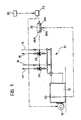
- a heating system is generally indicated 10 and comprises a water circulation boiler 12 connected to liquid delivery pipes 14 and pipes 16 for the liquid returning from the radiators (not illustrated) situated in the space to be heated.
- a burner and a minimum temperature immersion thermostat 20 are associated with the boiler (12).
- the system 10 is provided with an electrical control panel 22 connected to an ambient temperature thermostat 24, to the burner 18 and, with the interposition of an electronic economiser device 26, to the liquid circulation pumps 28 situated in the delivery pipes 14.
- the operation of the circulation pumps 28 is controlled by means of the device 26 subject to the consent of both the minimum thermostat 20 of the boiler 12 and the ambient thermostat 24.
- the pumps 28 operate for a predetermined time set by means of a timer 26a of the economiser device 26, provided that the thermostats 20 and 24 consent thereto.
- the pumps 28 are stopped by the device 26 and remain in this condition for a predetermined time set by means of a second timer 26b independently of the consent of the thermostats 20 and 24.
- the economiser device 26 is provided with a third timer 26c arranged to enable the operation of the circulation pumps 28 for a predetermined time greater than the time normally set by the first timer 26a.
- the operation of the pumps 28 during the transitory phase controlled by the third timer 26c is, however, conditional on the consent of the thermostats 20 and 24, the former not permitting the pumps to start if the temperature of the liquid in the boiler has not reached a certain value and the latter not permitting the pumps 28 (and at the same time the burner 18) to start if the ambient conditions do not require the system to be started.
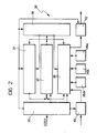
- the electronic economiser device 26 ( Figure 2) has a supply 30, a microprocessor 32, read-only and random-access memory devices 34, a parallel interface 36, a clock and addressing circuit 38, an input interface circuit 40 connected to the thermostat 20, and an output interface circuit 42 connected to the circulation pumps 28.
- the supply 30 comprises a transformer, a rectifier, a stabilizer and a back-up battery.
- the microprocessor 32 is of the Z80 type, while the memory devices 34 are of EPROM 2732 and RAM 6116 types.
- the parallel interface 36 connected to the timers 26a, 26b, and 26c is of the Z80-Plo type.
- the components of the circuit of the electronic device 26 are connected to each other in the manner illustrated in Figure 2.
- a CTC-type boiler with a nominal output of 60,200 kilocalories/hour and 66,134 kilocalories/hour at the furnace was used in association with a Cuneod C10-type gas oil burner provided with a 4 kg/hour Monarch nozzle (45°C, supply pressure 13 Bars).
- a 32/22-type circulation pump produced by VEMA was used.
- the above boiler was serving a building of approximately 1400 cubic metres heated by means of a system of pipes and associated radiators and having a total of 513 litres of water in the system.
- the circulation pump operated for a period of 9 minutes programmed by means of the third timer 26c. After the pump had operated for 2 minutes, the radiating bodies of the system were at 55°C and the water in the boiler was at 45°C. In this condition, the minimum thermostat 20 of the boiler, set at 60°C, had already interrupted the operation of the circulation pump without switching off the timer 26c. In this intermediate phase, in which the circulation pump is not operating, the radiators are not cooled by the water coming from the boiler and the latter attains maximum temperature conditions again in approximately 5 minutes.
- the minimum temperature thermostat of the boiler and the third timer cooperate with each other so that, if the set interval has not yet ended and the water is at a temperature lower than the value set by the minimum temperature thermostat 20 (for example 60°C), the pump does not operate but starts again to complete the programmed interval as soon as the limit temperature set by the minimum temperature thermostat of the boiler has been reached. It was found that the circulation pump, in order to obtain a stable running temperature of approximately 55-60°C, had operated for the 9 minutes programmed and had required, in the various intervals during which the temperature in the boiler was lower than the minimum, approximately 25 minutes of operation of the burner.
- the radiators of the system used in the test had taken 9-10 minutes to lose heat to the atmosphere and fall to a temperature of approximately 50°C.
- the second timer 26b was set at an 8-minute period of interruption of operation of the circulation pump. Subsequently, it was found that the pump had to operate for about 2 minutes to bring the temperature of the radiators back to 65°C. It was noted that a particular choice of duration of the intervals (a double cycle of 2 minutes of operation of the pump and 8 minutes of interruption) covered the thermal range from the maximum to the minimum temperature in the boiler provided for respectively by the maximum temperature thermostat (not illustrated) and the minimum temperature thermostat in the boiler.
- a total of 42 kg of gas oil was used with the circulation pump operating intermittently for a total of 4 hours.
- Example 2 The same heating system was used as in Example 1, but without the electronic economiser device. In this configuration, a maximum temperature boiler thermostat was connected to the electrical control panel according to normal practice for installation and operation of heating systems.
Landscapes
- Engineering & Computer Science (AREA)
- Physics & Mathematics (AREA)
- Thermal Sciences (AREA)
- Chemical & Material Sciences (AREA)
- Combustion & Propulsion (AREA)
- Mechanical Engineering (AREA)
- General Engineering & Computer Science (AREA)
- Steam Or Hot-Water Central Heating Systems (AREA)
- Sorption Type Refrigeration Machines (AREA)
- General Induction Heating (AREA)
- Cookers (AREA)
Priority Applications (1)
| Application Number | Priority Date | Filing Date | Title |
|---|---|---|---|
| AT87830269T ATE67293T1 (de) | 1987-03-24 | 1987-07-15 | Heizungsanlage. |
Applications Claiming Priority (2)
| Application Number | Priority Date | Filing Date | Title |
|---|---|---|---|
| IT100287 | 1987-03-24 | ||
| IT01002/87A IT1218475B (it) | 1987-03-24 | 1987-03-24 | E conomizzatore per riscaldamento |
Publications (3)
| Publication Number | Publication Date |
|---|---|
| EP0283633A2 true EP0283633A2 (de) | 1988-09-28 |
| EP0283633A3 EP0283633A3 (en) | 1988-11-23 |
| EP0283633B1 EP0283633B1 (de) | 1991-09-11 |
Family
ID=11100292
Family Applications (1)
| Application Number | Title | Priority Date | Filing Date |
|---|---|---|---|
| EP87830269A Expired - Lifetime EP0283633B1 (de) | 1987-03-24 | 1987-07-15 | Heizungsanlage |
Country Status (7)
| Country | Link |
|---|---|
| US (1) | US4944453A (de) |
| EP (1) | EP0283633B1 (de) |
| AT (1) | ATE67293T1 (de) |
| DE (1) | DE3772972D1 (de) |
| ES (1) | ES2025698T3 (de) |
| GR (1) | GR3002726T3 (de) |
| IT (1) | IT1218475B (de) |
Cited By (1)
| Publication number | Priority date | Publication date | Assignee | Title |
|---|---|---|---|---|
| WO1998053257A1 (en) * | 1997-05-19 | 1998-11-26 | Honeywell Control Systems Limited | Pump control |
Families Citing this family (2)
| Publication number | Priority date | Publication date | Assignee | Title |
|---|---|---|---|---|
| US20070056299A1 (en) * | 2005-09-15 | 2007-03-15 | Shankweiler Matthew C | Modified thermostatic control for enhanced air quality |
| ITMI20060552A1 (it) | 2006-03-24 | 2007-09-25 | Del Col Ugo Enrico | Metodo e sistema per controllare un impianto di riscaldamento |
Family Cites Families (5)
| Publication number | Priority date | Publication date | Assignee | Title |
|---|---|---|---|---|
| US2751155A (en) * | 1955-05-20 | 1956-06-19 | Ira Milton Jones | Hot water heating system control |
| DE2731922A1 (de) * | 1977-05-06 | 1978-11-09 | Elesta Ag Elektronik | Schutzschaltung gegen niedertemperaturkorrosion des heizkessels |
| CH641889A5 (de) * | 1980-02-04 | 1984-03-15 | Landis & Gyr Ag | Heizungsanlage. |
| US4410135A (en) * | 1980-11-04 | 1983-10-18 | Skyinskus Robert L | Controller for a room heating system |
| US4787555A (en) * | 1985-09-24 | 1988-11-29 | Alfred T. Newell, III | Environmental control system with condition responsive timer and method |
-
1987
- 1987-03-24 IT IT01002/87A patent/IT1218475B/it active
- 1987-07-15 DE DE8787830269T patent/DE3772972D1/de not_active Expired - Lifetime
- 1987-07-15 EP EP87830269A patent/EP0283633B1/de not_active Expired - Lifetime
- 1987-07-15 ES ES198787830269T patent/ES2025698T3/es not_active Expired - Lifetime
- 1987-07-15 AT AT87830269T patent/ATE67293T1/de active
-
1988
- 1988-09-23 US US07/248,014 patent/US4944453A/en not_active Expired - Fee Related
-
1991
- 1991-09-16 GR GR91401341T patent/GR3002726T3/el unknown
Cited By (1)
| Publication number | Priority date | Publication date | Assignee | Title |
|---|---|---|---|---|
| WO1998053257A1 (en) * | 1997-05-19 | 1998-11-26 | Honeywell Control Systems Limited | Pump control |
Also Published As
| Publication number | Publication date |
|---|---|
| ES2025698T3 (es) | 1992-04-01 |
| DE3772972D1 (de) | 1991-10-17 |
| EP0283633B1 (de) | 1991-09-11 |
| US4944453A (en) | 1990-07-31 |
| EP0283633A3 (en) | 1988-11-23 |
| IT1218475B (it) | 1990-04-19 |
| GR3002726T3 (en) | 1993-01-25 |
| ATE67293T1 (de) | 1991-09-15 |
| IT8701002A0 (it) | 1987-03-24 |
Similar Documents
| Publication | Publication Date | Title |
|---|---|---|
| US4399862A (en) | Method and apparatus for proven demand air conditioning control | |
| DE3375427D1 (en) | Process and installation for bi-energetic central heating | |
| US7500453B2 (en) | Boiler control unit | |
| GB1193711A (en) | Improvements in or relating to the Control of Thermal Conditioning Systems | |
| US4106690A (en) | Optimum start controller | |
| US4944453A (en) | Heating system | |
| US4410135A (en) | Controller for a room heating system | |
| WO2004001297A1 (en) | Boiler control unit | |
| GB1425790A (en) | Methods of regulating and monitoring a heating installation including a gas burner for room heating and for providing hot water for consumption purposes | |
| JPH0160740B2 (de) | ||
| GB2384552A (en) | A hot water boiler which prevents excess heat build-up | |
| JP3371703B2 (ja) | 貯湯式給湯装置 | |
| GB2175996A (en) | Heating installation control apparatus | |
| EP0292133B1 (de) | Regelung eines Heizkessels | |
| US2668664A (en) | Temperature control for heating systems | |
| JPS5634049A (en) | Heater | |
| JPH0315972Y2 (de) | ||
| GB2161293A (en) | Sequence controller | |
| JPH04295547A (ja) | 温風暖房機のタイマー運転方法 | |
| JPH07167499A (ja) | 電気温水器 | |
| JPS61110840A (ja) | 電気温水器の制御装置 | |
| JPS57131940A (en) | Heating apparatus by hot water | |
| JPH0293239A (ja) | 加熱装置 | |
| JPS588941A (ja) | ヒ−トポンプ式給湯機の制御装置 | |
| JP2897491B2 (ja) | 貯湯式給湯器の制御方法 |
Legal Events
| Date | Code | Title | Description |
|---|---|---|---|
| PUAI | Public reference made under article 153(3) epc to a published international application that has entered the european phase |
Free format text: ORIGINAL CODE: 0009012 |
|
| AK | Designated contracting states |
Kind code of ref document: A2 Designated state(s): AT BE CH DE ES FR GB GR IT LI LU NL SE |
|
| PUAL | Search report despatched |
Free format text: ORIGINAL CODE: 0009013 |
|
| AK | Designated contracting states |
Kind code of ref document: A3 Designated state(s): AT BE CH DE ES FR GB GR IT LI LU NL SE |
|
| 17P | Request for examination filed |
Effective date: 19881201 |
|
| 17Q | First examination report despatched |
Effective date: 19900109 |
|
| GRAA | (expected) grant |
Free format text: ORIGINAL CODE: 0009210 |
|
| AK | Designated contracting states |
Kind code of ref document: B1 Designated state(s): AT BE CH DE ES FR GB GR IT LI LU NL SE |
|
| REF | Corresponds to: |
Ref document number: 67293 Country of ref document: AT Date of ref document: 19910915 Kind code of ref document: T |
|
| ITF | It: translation for a ep patent filed | ||
| ITPR | It: changes in ownership of a european patent |
Owner name: OFFERTA DI LICENZA AL PUBBLICO |
|
| REF | Corresponds to: |
Ref document number: 3772972 Country of ref document: DE Date of ref document: 19911017 |
|
| ET | Fr: translation filed | ||
| REG | Reference to a national code |
Ref country code: ES Ref legal event code: FG2A Ref document number: 2025698 Country of ref document: ES Kind code of ref document: T3 |
|
| REG | Reference to a national code |
Ref country code: GB Ref legal event code: 746 |
|
| PLBE | No opposition filed within time limit |
Free format text: ORIGINAL CODE: 0009261 |
|
| STAA | Information on the status of an ep patent application or granted ep patent |
Free format text: STATUS: NO OPPOSITION FILED WITHIN TIME LIMIT |
|
| 26N | No opposition filed | ||
| REG | Reference to a national code |
Ref country code: GR Ref legal event code: FG4A Free format text: 3002726 |
|
| REG | Reference to a national code |
Ref country code: FR Ref legal event code: DL |
|
| EPTA | Lu: last paid annual fee | ||
| EAL | Se: european patent in force in sweden |
Ref document number: 87830269.4 |
|
| PGFP | Annual fee paid to national office [announced via postgrant information from national office to epo] |
Ref country code: GB Payment date: 19960108 Year of fee payment: 9 |
|
| PGFP | Annual fee paid to national office [announced via postgrant information from national office to epo] |
Ref country code: ES Payment date: 19960112 Year of fee payment: 9 |
|
| PGFP | Annual fee paid to national office [announced via postgrant information from national office to epo] |
Ref country code: BE Payment date: 19960116 Year of fee payment: 9 |
|
| PGFP | Annual fee paid to national office [announced via postgrant information from national office to epo] |
Ref country code: SE Payment date: 19960117 Year of fee payment: 9 Ref country code: AT Payment date: 19960117 Year of fee payment: 9 |
|
| PGFP | Annual fee paid to national office [announced via postgrant information from national office to epo] |
Ref country code: NL Payment date: 19960123 Year of fee payment: 9 Ref country code: GR Payment date: 19960123 Year of fee payment: 9 |
|
| PGFP | Annual fee paid to national office [announced via postgrant information from national office to epo] |
Ref country code: DE Payment date: 19960124 Year of fee payment: 9 |
|
| PGFP | Annual fee paid to national office [announced via postgrant information from national office to epo] |
Ref country code: FR Payment date: 19960129 Year of fee payment: 9 |
|
| PGFP | Annual fee paid to national office [announced via postgrant information from national office to epo] |
Ref country code: LU Payment date: 19960201 Year of fee payment: 9 |
|
| REG | Reference to a national code |
Ref country code: CH Ref legal event code: PL |
|
| PGFP | Annual fee paid to national office [announced via postgrant information from national office to epo] |
Ref country code: CH Payment date: 19960318 Year of fee payment: 9 |
|
| PG25 | Lapsed in a contracting state [announced via postgrant information from national office to epo] |
Ref country code: LU Free format text: LAPSE BECAUSE OF NON-PAYMENT OF DUE FEES Effective date: 19960715 Ref country code: GB Effective date: 19960715 Ref country code: AT Effective date: 19960715 |
|
| PG25 | Lapsed in a contracting state [announced via postgrant information from national office to epo] |
Ref country code: SE Effective date: 19960716 Ref country code: ES Free format text: LAPSE BECAUSE OF THE APPLICANT RENOUNCES Effective date: 19960716 |
|
| PG25 | Lapsed in a contracting state [announced via postgrant information from national office to epo] |
Ref country code: LI Effective date: 19960731 Ref country code: CH Effective date: 19960731 Ref country code: BE Effective date: 19960731 |
|
| BERE | Be: lapsed |
Owner name: RONZANI ARTEMIO Effective date: 19960731 |
|
| PG25 | Lapsed in a contracting state [announced via postgrant information from national office to epo] |
Ref country code: GR Free format text: THE PATENT HAS BEEN ANNULLED BY A DECISION OF A NATIONAL AUTHORITY Effective date: 19970131 |
|
| PG25 | Lapsed in a contracting state [announced via postgrant information from national office to epo] |
Ref country code: NL Effective date: 19970201 |
|
| REG | Reference to a national code |
Ref country code: GR Ref legal event code: MM2A Free format text: 3002726 |
|
| GBPC | Gb: european patent ceased through non-payment of renewal fee |
Effective date: 19960715 |
|
| REG | Reference to a national code |
Ref country code: CH Ref legal event code: PL |
|
| PG25 | Lapsed in a contracting state [announced via postgrant information from national office to epo] |
Ref country code: FR Effective date: 19970328 |
|
| NLV4 | Nl: lapsed or anulled due to non-payment of the annual fee |
Effective date: 19970201 |
|
| PG25 | Lapsed in a contracting state [announced via postgrant information from national office to epo] |
Ref country code: DE Effective date: 19970402 |
|
| EUG | Se: european patent has lapsed |
Ref document number: 87830269.4 |
|
| REG | Reference to a national code |
Ref country code: FR Ref legal event code: ST Ref country code: CH Ref legal event code: AEN Free format text: LE BREVET A ETE RADIE PAR ERREUR. IL EST REACTIVE. |
|
| REG | Reference to a national code |
Ref country code: ES Ref legal event code: FD2A Effective date: 19991007 |
|
| PG25 | Lapsed in a contracting state [announced via postgrant information from national office to epo] |
Ref country code: IT Free format text: LAPSE BECAUSE OF NON-PAYMENT OF DUE FEES;WARNING: LAPSES OF ITALIAN PATENTS WITH EFFECTIVE DATE BEFORE 2007 MAY HAVE OCCURRED AT ANY TIME BEFORE 2007. THE CORRECT EFFECTIVE DATE MAY BE DIFFERENT FROM THE ONE RECORDED. Effective date: 20050715 |