EP0283694B1 - Dispositif de verrouillage pour vérin à fluide - Google Patents
Dispositif de verrouillage pour vérin à fluide Download PDFInfo
- Publication number
- EP0283694B1 EP0283694B1 EP88101899A EP88101899A EP0283694B1 EP 0283694 B1 EP0283694 B1 EP 0283694B1 EP 88101899 A EP88101899 A EP 88101899A EP 88101899 A EP88101899 A EP 88101899A EP 0283694 B1 EP0283694 B1 EP 0283694B1
- Authority
- EP
- European Patent Office
- Prior art keywords
- pressure
- pressure medium
- braking
- cylinder
- switch valve
- Prior art date
- Legal status (The legal status is an assumption and is not a legal conclusion. Google has not performed a legal analysis and makes no representation as to the accuracy of the status listed.)
- Expired
Links
- 239000012530 fluid Substances 0.000 title description 2
- 230000033001 locomotion Effects 0.000 claims abstract description 12
- 230000005284 excitation Effects 0.000 claims description 8
- 230000006870 function Effects 0.000 description 6
- 230000002950 deficient Effects 0.000 description 2
- 238000010586 diagram Methods 0.000 description 2
- 238000006073 displacement reaction Methods 0.000 description 2
- 238000009434 installation Methods 0.000 description 2
- 238000000034 method Methods 0.000 description 2
- 238000012986 modification Methods 0.000 description 2
- 230000004048 modification Effects 0.000 description 2
- 230000005540 biological transmission Effects 0.000 description 1
- 230000007423 decrease Effects 0.000 description 1
- 230000007547 defect Effects 0.000 description 1
- 230000007812 deficiency Effects 0.000 description 1
- 230000001419 dependent effect Effects 0.000 description 1
- ZINJLDJMHCUBIP-UHFFFAOYSA-N ethametsulfuron-methyl Chemical compound CCOC1=NC(NC)=NC(NC(=O)NS(=O)(=O)C=2C(=CC=CC=2)C(=O)OC)=N1 ZINJLDJMHCUBIP-UHFFFAOYSA-N 0.000 description 1
- 230000005281 excited state Effects 0.000 description 1
- 239000013589 supplement Substances 0.000 description 1
- 238000013022 venting Methods 0.000 description 1
Images


Classifications
-
- F—MECHANICAL ENGINEERING; LIGHTING; HEATING; WEAPONS; BLASTING
- F15—FLUID-PRESSURE ACTUATORS; HYDRAULICS OR PNEUMATICS IN GENERAL
- F15B—SYSTEMS ACTING BY MEANS OF FLUIDS IN GENERAL; FLUID-PRESSURE ACTUATORS, e.g. SERVOMOTORS; DETAILS OF FLUID-PRESSURE SYSTEMS, NOT OTHERWISE PROVIDED FOR
- F15B15/00—Fluid-actuated devices for displacing a member from one position to another; Gearing associated therewith
- F15B15/08—Characterised by the construction of the motor unit
- F15B15/082—Characterised by the construction of the motor unit the motor being of the slotted cylinder type
-
- F—MECHANICAL ENGINEERING; LIGHTING; HEATING; WEAPONS; BLASTING
- F15—FLUID-PRESSURE ACTUATORS; HYDRAULICS OR PNEUMATICS IN GENERAL
- F15B—SYSTEMS ACTING BY MEANS OF FLUIDS IN GENERAL; FLUID-PRESSURE ACTUATORS, e.g. SERVOMOTORS; DETAILS OF FLUID-PRESSURE SYSTEMS, NOT OTHERWISE PROVIDED FOR
- F15B15/00—Fluid-actuated devices for displacing a member from one position to another; Gearing associated therewith
- F15B15/20—Other details, e.g. assembly with regulating devices
- F15B15/26—Locking mechanisms
- F15B15/261—Locking mechanisms using positive interengagement, e.g. balls and grooves, for locking in the end positions
-
- F—MECHANICAL ENGINEERING; LIGHTING; HEATING; WEAPONS; BLASTING
- F15—FLUID-PRESSURE ACTUATORS; HYDRAULICS OR PNEUMATICS IN GENERAL
- F15B—SYSTEMS ACTING BY MEANS OF FLUIDS IN GENERAL; FLUID-PRESSURE ACTUATORS, e.g. SERVOMOTORS; DETAILS OF FLUID-PRESSURE SYSTEMS, NOT OTHERWISE PROVIDED FOR
- F15B15/00—Fluid-actuated devices for displacing a member from one position to another; Gearing associated therewith
- F15B15/20—Other details, e.g. assembly with regulating devices
- F15B15/26—Locking mechanisms
- F15B15/262—Locking mechanisms using friction, e.g. brake pads
-
- F—MECHANICAL ENGINEERING; LIGHTING; HEATING; WEAPONS; BLASTING
- F15—FLUID-PRESSURE ACTUATORS; HYDRAULICS OR PNEUMATICS IN GENERAL
- F15B—SYSTEMS ACTING BY MEANS OF FLUIDS IN GENERAL; FLUID-PRESSURE ACTUATORS, e.g. SERVOMOTORS; DETAILS OF FLUID-PRESSURE SYSTEMS, NOT OTHERWISE PROVIDED FOR
- F15B15/00—Fluid-actuated devices for displacing a member from one position to another; Gearing associated therewith
- F15B15/20—Other details, e.g. assembly with regulating devices
- F15B15/26—Locking mechanisms
- F15B15/265—Locking mechanisms specially adapted for rodless pistons or slotted cylinders
Definitions
- the invention relates to a braking device for pressure medium cylinders, in particular rodless cylinders, with a brake element which can be tightened by means of pressure medium application and whose pressure medium application is monitored by a switching valve.
- Such braking devices are shown, for example, in EP-A 104 364 for rodless cylinders, the braking member being arranged integrated in the power take-off member.
- the known brake devices mentioned have the defect to solve in the event of an undesired loss of pressure, which often cannot be permitted for safety reasons.
- spring-loaded brakes that is to say to apply them with spring force and to release them by means of pressure medium.
- a pressure medium accumulator which can be charged via a check valve from a pressure medium source is arranged between a pressure medium source and the switching valve, which is designed as a 3/2-way valve, in that the pressure of the pressure medium source acts on a pressure switch which, when the pressure falls below a first one , high pressure threshold switches the switching valve to opening an otherwise closed connection from the pressure medium store to the braking element, that a spring-loaded cylinder acted upon from the pressure medium memory is provided, which activates a mechanical movement lock arranged in parallel with the braking element when subjected to a pressure exceeding a second, medium pressure threshold, and that the braking member is designed to hold the nominal load of the pressure medium cylinder until the pressure drops below a third, low pressure threshold.
- a pressure medium connection 2 leads from a pressure medium source 1, here a compressed air source, through a check valve 3 to a pressure medium reservoir 4 designed as a container.
- a pressure switch 5 is connected to the pressure medium connection 2, which is above a relatively high spring 6 by an adjustable spring 6 adjustable pressure threshold in the pressure medium connection 2 closes a switch 7 and keeps it open below this pressure threshold.
- a switching valve designed as a solenoid valve 8 and representing a 3/2-way valve, is connected to the pressure medium accumulator and connects the pressure medium accumulator 4 to a pressure medium connection 10 leading to braking elements 9 in the de-energized state; in the de-energized state, the solenoid valve 8 blocks this connection and keeps the pressure medium connection 10 depressurized, for example in the illustrated pneumatic system, vented to the atmosphere.
- the switch 7 is arranged in an electrical connection 11 from a current source symbolized only by a plus sign to the excitation coil of the solenoid valve 8. Furthermore, the pressure chamber 12 of a spring-loaded cylinder 13 is connected to the pressure medium reservoir 4, the piston rod 14 of which extends under the force of the spring 15 when the pressure falls below a second, medium pressure threshold in the pressure chamber 12. In the retracted state, the piston rod 14, which represents a locking pin, ends in front of a perforated strip 16 located in front of the spring-loaded cylinder 13; in the extended state, the piston rod 14 can engage in the holes 17 in the perforated strip 16. The piston rod 14 thus forms, together with the perforated strip 16, a mechanical, switchable movement lock 14, 16.
- the braking device described above is arranged on a pressure medium cylinder (not shown in FIG. 1) with at least one fixed part and one part that can move under pressure medium in such a way that the check valve 3, the pressure monitor 5, the pressure medium accumulator 4, the solenoid valve 8, the braking members 9 and the Spring cylinder 13 on one and the perforated strip 16 on the other of the two parts.
- the perforated strip 16 is expediently fixed, in a conventional piston rod cylinder vice versa to arrange the perforated strip 16 movably with the piston rod.
- the braking members 9 are constructed in the usual way as a friction brake; they can, as can be seen from EP-A 104 364 already mentioned at the beginning, each have a cylinder or bellows which can be pressurized by the pressure medium connection 10 and which, when pressurized, has a friction element, in particular a brake shoe or presses a brake lining onto the other part of the pressure cylinder which is relatively displaceable for this purpose.
- the pressure medium cylinder can be equipped with a further, customary brake, for example according to EP-A 104 364 mentioned, which is used as a service brake in normal operation of the pressure medium cylinder.
- the braking device according to Fig. 1 acts as follows:
- the switch 7 is closed and the solenoid valve 8 is thus energized when the current source is functioning.
- the pressure medium reservoir 4 is filled by the check valve 3 from the pressure medium source 1, but the energized solenoid valve 8 keeps the braking members 9 depressurized and thus released.
- the spring-loaded cylinder 13 is acted upon from the pressure medium reservoir 4, so that its piston rod 14 is retracted and out of engagement with the perforated strip 16. If the pressure at the pressure medium source 1 drops due to any damage, the switch 7 of the pressure switch 5 opens when the pressure falls below a first, still relatively high pressure threshold and thus interrupts the excitation of the solenoid valve 8.
- the solenoid valve 8 therefore switches to the switch position shown um, whereby it separates the braking members 9 from the atmosphere and instead connects to the pressure medium accumulator 4.
- the braking elements 9 are therefore pressurized from the pressure medium store 4 and tighten, so that the pressure medium cylinder is braked in its current position. Since the pressure drop in the pressure medium source 1 via the check valve 3 means that there is no further pressure make-up in the pressure medium reservoir 4, a compensating pressure is established between the pressure medium reservoir 4 and the pressurized spaces of the braking members 9, which, however, is considerably higher than the pressure level by appropriately dimensioning the volume of the pressure medium reservoir 4 which is required to safely brake the pressure medium cylinder under its nominal load.
- the spring-loaded cylinder 13 remains in its tensioned position, the piston rod 14 thus remains disengaged from the perforated strip 16.
- the compensating pressure prevailing in these rooms gradually drops. If the pressure falls below a second, medium pressure threshold, the storage spring 15 of the spring-loaded cylinder 13 pushes out the piston rod 14 so that it engages with the perforated strip 16. In general, the piston rod 14 will not yet engage in one of the holes 17 in the perforated strip 16, but will stand on the surface 18 of the perforated strip 16 facing the spring accumulator 13. At this medium pressure threshold mentioned, the application pressure is still sufficient to securely apply the braking elements 9. If the leak continues, the pressure in the pressure medium reservoir 4 and the spaces connected to it further decreases.
- the pressure medium cylinder is thus locked in a form-fitting manner, so no further movement can take place. If, by chance, the piston rod 14 immediately engages in one of the holes 17 when it is extended, the aforementioned slipping of the pressure medium cylinder is of course not required; the pressure medium cylinder is locked in a positive manner without slipping.
- the storage spring 15 is only slightly loaded when the piston of the spring storage cylinder 13 is suitably dimensioned, and can therefore be designed to be fatigue-free and unbreakable.
- a further switch 19 indicated only by dashed lines, in the electrical connection between the current source and the switch 7, possibly also in the connection 11:
- this switch 19 can be used for serve the operational actuation of the braking members 9, so no further service brake is required in this case.
- the switch 19 is to be closed, the excitation of the solenoid valve 8 keeps the brake members 9 depressurized and thus released, while when the switch 19 is opened the excitation of the solenoid valve 8 is interrupted and the brake members are pressurized to brake will.
- the switch 19, as is customary for service brakes, can be switched by any stops or a control program for the pressure medium cylinder.
- FIG. 2 shows a braking device corresponding to that of FIG. 1, but the braking members are designed as a dual-circuit brake with the braking members 9 and 9 'for one braking circuit each, this dual-circuiting serves to further increase operational safety.
- the parts corresponding to FIG. 1 are given the same reference numerals in FIG. 2 and therefore require no further explanation.
- a pressure medium connection 20 leads from solenoid valve 8 to an inlet of a 5/3-way valve. 21, which is stabilized in its middle switching position by two springs 22.
- the two output connections of the directional control valve 21 are each connected to the braking members 9 and 9 'via a pressure medium connection 10' and 23, respectively.
- Branch channels lead from the pressure medium connections 10 'and 23 to the end-side loading chambers of the directional control valve 21, which switch these directional control valve 21 into one of its two end positions when the pressure medium is acted on unevenly.
- the directional control valve 21 connects the pressure medium connection 20 to the two pressure medium connections 10 'and 23, so that both braking circuits are pressurized during braking operations, as described above for FIG. 1, and thus the braking members 9 and 9' have been applied .
- the directional control valve 21 is therefore pressurized on one side via the branch channels and switches to one of its lateral limit switch positions, in which the pressure medium connection 20 alone with the intact brake circuit for the braking members 9 or 9 'connects while the other, defective brake circuit is kept depressurized.
- the function of the braking device is thus ensured even in the case of a defective brake circuit. Otherwise, the function of the braking device according to FIG. 2 corresponds to that according to FIG. 1.
- FIG. 3 To use the braking elements provided for the braking device also for the service braking of the pressure medium cylinder required in normal operation, an arrangement according to FIG. 3 can be provided in a further modification:
- the check valve 3, the pressure switch 5, the air container 4 and the spring accumulator 13 combined into a structural unit, which is symbolized by a square 24, to which on the one hand the pressure medium source 1 and on the other hand a solenoid valve 8 'is connected.
- the line 10 or 20 extends from the solenoid valve 8 'according to FIG. 1 or 2.
- the solenoid valve 8 'does not connect the pressure medium connection 10 or 20 to the atmosphere, but rather to a further solenoid valve 25; in the de-energized state, the connections and functions described in FIGS. 1 and 2 are effected.
- the solenoid valve 25 is designed as a 3/2-way valve, in the unexcited state it connects a pressure medium source 1 ', which may correspond to the pressure medium source 1, to the solenoid valve 8', in the excited state it keeps the connection to the solenoid valve 8 'depressurized.
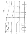
- p3 means the pressure applied to the braking elements, that is to say the pressure prevailing in the pressure medium connection 10 or 20, p2 the pressure in the pressure medium reservoir 4, p v the pressure of the pressure medium source 1 and I the excitation current for the solenoid valve 8 or 8 '.
- the time course is plotted on the abscissa.
- T the pressure medium and the current source are intact.
- T occurs during the period between the times t 1 and tz a controlled by closing the switch 19 release process, the solenoid valve 8 picks up during this period, so that the pressure p 3 drops and the braking members 9 release.
- the pressure in the pressure medium reservoir 4 has dropped to a value at which the spring-loaded cylinder 13 responds and the piston rod 14 extends; however, the braking members 9 are still securely applied. If there is a further loss of pressure, the pressure drops below the pressure in the braking elements 9 at which they begin to slip under load with the nominal load of the pressure medium cylinder, at the latest immediately after this point in time, the piston rod 14 engages in a hole 17 in the perforated strip 16 and locks the pressure medium cylinder in a form-fitting manner . It can thus be seen that if the pressure medium source fails, the frictional braking elements 9 are actuated and if there is a subsequent pressure loss due to leakage, a positive locking takes place.
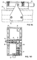
- a rodless cylinder 26 is indicated in front view, top view and side view with broken lines, which cylinder is provided with a slide or force output element 27 shown in solid lines.
- the force output element 27 includes a braking element, as is known, for example, from EP-A mentioned at the beginning. From FIG. 5B, which shows a section along the line A-B in FIG. 5A, it can be seen that the force output element 27 contains cavities 28 which serve as pressure medium stores. Furthermore, a recess 29 for receiving a check valve and a further recess 30 for receiving a pressure switch 31 are provided, the pressure switch 31, in contrast to FIG.
- the spring storage cylinder 13 with the storage spring 15 and the piston rod 14 is arranged in the center of the force output member 27, the piston rod 14 extends transversely to the longitudinal direction of the cylinder 26.
- a solenoid valve 32 is provided, which corresponds to the solenoid valve 25 according to FIG.
- the above-mentioned functional parts are connected by means of bores and channels running in the walls of the power output member 27.
- clamping grooves 33 On the outside of the cylinder 26 there are clamping grooves 33, one of which is clamped with a stop 35 by means of a clamping device 34.
- the stop 35 protrudes only when the piston rod is extended in its path of motion when the force output member 27 is moving. Overall, this results in a rodless cylinder which, with little additional effort and little increase in the required installation space, also has a frictional braking device which acts in emergencies and has a positive, has adjustable emergency stop by the clamping device 34.
- the braking device is also suitable for hydraulic pressure medium cylinders, the pressure medium accumulator must be designed accordingly and return lines must be provided instead of venting.
Landscapes
- Engineering & Computer Science (AREA)
- Physics & Mathematics (AREA)
- Fluid Mechanics (AREA)
- Mechanical Engineering (AREA)
- General Engineering & Computer Science (AREA)
- Valves And Accessory Devices For Braking Systems (AREA)
- Lock And Its Accessories (AREA)
- Braking Arrangements (AREA)
- Braking Systems And Boosters (AREA)
Claims (8)
Priority Applications (1)
| Application Number | Priority Date | Filing Date | Title |
|---|---|---|---|
| AT88101899T ATE45012T1 (de) | 1987-03-20 | 1988-02-10 | Bremseinrichtung fuer druckmittelzylinder. |
Applications Claiming Priority (2)
| Application Number | Priority Date | Filing Date | Title |
|---|---|---|---|
| DE3709164 | 1987-03-20 | ||
| DE19873709164 DE3709164A1 (de) | 1987-03-20 | 1987-03-20 | Bremseinrichtung fuer druckmittelzylinder |
Publications (2)
| Publication Number | Publication Date |
|---|---|
| EP0283694A1 EP0283694A1 (fr) | 1988-09-28 |
| EP0283694B1 true EP0283694B1 (fr) | 1989-07-26 |
Family
ID=6323573
Family Applications (1)
| Application Number | Title | Priority Date | Filing Date |
|---|---|---|---|
| EP88101899A Expired EP0283694B1 (fr) | 1987-03-20 | 1988-02-10 | Dispositif de verrouillage pour vérin à fluide |
Country Status (3)
| Country | Link |
|---|---|
| EP (1) | EP0283694B1 (fr) |
| AT (1) | ATE45012T1 (fr) |
| DE (2) | DE3709164A1 (fr) |
Families Citing this family (3)
| Publication number | Priority date | Publication date | Assignee | Title |
|---|---|---|---|---|
| SE465787B (sv) * | 1990-02-09 | 1991-10-28 | Bo Granbom | Fastsaettningsanordning foer fastsaettning av en skena vid en manoevercylinder |
| DE102009034721B4 (de) | 2009-07-24 | 2026-01-08 | Dr. Ing. H.C. F. Porsche Aktiengesellschaft | Pneumatikanlage und Kraftfahrzeug |
| CN102392845B (zh) * | 2011-11-28 | 2014-08-20 | 巨力索具股份有限公司 | 无源锁紧液压系统 |
Citations (1)
| Publication number | Priority date | Publication date | Assignee | Title |
|---|---|---|---|---|
| EP0104364A1 (fr) * | 1982-08-05 | 1984-04-04 | Knorr-Bremse Ag | Vérin sans tige de piston avec frein |
Family Cites Families (7)
| Publication number | Priority date | Publication date | Assignee | Title |
|---|---|---|---|---|
| US2932282A (en) * | 1957-07-08 | 1960-04-12 | Roe L Mckinley | Fluid actuated systems for operating and locking control elements |
| US3033171A (en) * | 1960-09-07 | 1962-05-08 | Sperry Rand Corp | Interlocking means for hydraulic servomotor systems |
| US3654833A (en) * | 1970-06-29 | 1972-04-11 | Eaton Yale & Towne | Hydraulic control circuit |
| DE2610692C2 (de) * | 1976-03-13 | 1986-11-27 | L. Schuler GmbH, 7320 Göppingen | Antriebseinrichtung für eine mechanisch angetriebene Presse |
| DE2633322C2 (de) * | 1976-07-24 | 1985-07-18 | L. Schuler GmbH, 7320 Göppingen | Sicherheitssteuerung |
| DE2814163A1 (de) * | 1978-04-01 | 1979-10-11 | Teves Gmbh Alfred | Notversorgungssystem |
| DE3328292A1 (de) * | 1983-08-05 | 1985-02-21 | Robert Bosch Gmbh, 7000 Stuttgart | Arbeitszylinder mit bremseinrichtung |
-
1987
- 1987-03-20 DE DE19873709164 patent/DE3709164A1/de not_active Withdrawn
-
1988
- 1988-02-10 DE DE8888101899T patent/DE3860001D1/de not_active Expired
- 1988-02-10 EP EP88101899A patent/EP0283694B1/fr not_active Expired
- 1988-02-10 AT AT88101899T patent/ATE45012T1/de not_active IP Right Cessation
Patent Citations (1)
| Publication number | Priority date | Publication date | Assignee | Title |
|---|---|---|---|---|
| EP0104364A1 (fr) * | 1982-08-05 | 1984-04-04 | Knorr-Bremse Ag | Vérin sans tige de piston avec frein |
Also Published As
| Publication number | Publication date |
|---|---|
| DE3709164A1 (de) | 1988-09-29 |
| DE3860001D1 (en) | 1989-08-31 |
| EP0283694A1 (fr) | 1988-09-28 |
| ATE45012T1 (de) | 1989-08-15 |
Similar Documents
| Publication | Publication Date | Title |
|---|---|---|
| DE102008015249B4 (de) | Druckmittelbetätigte Bremsanlage eines Fahrzeugs mit wenigstens einem bistabilen Schieberventil | |
| EP2238004B1 (fr) | Frein de stationnement | |
| EP0877693B1 (fr) | Systeme combine de frein de service et de frein de stationnement | |
| EP1446312A2 (fr) | Systeme de freinage electro-hydraulique pour automobiles | |
| DE2142552C2 (de) | Drucksteuerventil für eine Antiblockierregelanlage | |
| DE1218891B (de) | Druckmittelbremsanlage fuer Fahrzeuge, insbesondere Kraftfahrzeuge | |
| EP0283694B1 (fr) | Dispositif de verrouillage pour vérin à fluide | |
| EP0881134B1 (fr) | Accumulateur d'energie | |
| DE3517958C2 (de) | Druckgesteuertes Ventil, insbesondere für Kraftfahrzeugbremsanlagen mit Bremsschlupfregelung | |
| DE3608567A1 (de) | Elektromagnetisch betreibbarer druckmodulator | |
| DE2616851A1 (de) | Bremsanlage fuer fahrzeuge | |
| WO1988006684A1 (fr) | Ensemble piston verrouillable a verin de serrage | |
| DE19851251C2 (de) | Bremssystem für rotatorisch und/oder translatorisch bewegliche Teile | |
| DE2738948C2 (de) | Drucksteuerventil zur Steuerung des Vorderachsbremsdruckes in pneumatischen Zweikreis-Fahrzeugbremsanlagen | |
| DE2261381C3 (de) | Lastabhängiger Bremskraftregler, für eine Fahrzeugbremsanlage | |
| DE2645471C2 (de) | Kraftverstärker für Hydraulikanlagen, insbesondere Bremsanlagen | |
| DE2708629A1 (de) | Druckmittelbremseinrichtung, insbesondere fuer schienenfahrzeuge | |
| DE3736750C2 (fr) | ||
| DE3137438A1 (de) | Speicherlade-wegeventil | |
| WO1991019108A1 (fr) | Equipement de commande pour un cylindre de travail | |
| EP0253315A1 (fr) | Filtre-presse | |
| DE2544172C2 (de) | Drucksteuereinrichtung für eine Antiblockier-Regelanlage | |
| DE2520461C2 (de) | Lastwechselventil in Druckmittelbremseinrichtungen, insbesondere für Schienenfahrzeuge | |
| WO2004020864A1 (fr) | Etrier de frein | |
| EP0602417B1 (fr) | Vérin de travail sans tige |
Legal Events
| Date | Code | Title | Description |
|---|---|---|---|
| PUAI | Public reference made under article 153(3) epc to a published international application that has entered the european phase |
Free format text: ORIGINAL CODE: 0009012 |
|
| AK | Designated contracting states |
Kind code of ref document: A1 Designated state(s): AT BE CH DE GB IT LI NL SE |
|
| 17P | Request for examination filed |
Effective date: 19880812 |
|
| 17Q | First examination report despatched |
Effective date: 19890110 |
|
| ITF | It: translation for a ep patent filed | ||
| GRAA | (expected) grant |
Free format text: ORIGINAL CODE: 0009210 |
|
| AK | Designated contracting states |
Kind code of ref document: B1 Designated state(s): AT BE CH DE GB IT LI NL SE |
|
| REF | Corresponds to: |
Ref document number: 45012 Country of ref document: AT Date of ref document: 19890815 Kind code of ref document: T |
|
| REF | Corresponds to: |
Ref document number: 3860001 Country of ref document: DE Date of ref document: 19890831 |
|
| GBT | Gb: translation of ep patent filed (gb section 77(6)(a)/1977) | ||
| PLBE | No opposition filed within time limit |
Free format text: ORIGINAL CODE: 0009261 |
|
| STAA | Information on the status of an ep patent application or granted ep patent |
Free format text: STATUS: NO OPPOSITION FILED WITHIN TIME LIMIT |
|
| 26N | No opposition filed | ||
| PGFP | Annual fee paid to national office [announced via postgrant information from national office to epo] |
Ref country code: GB Payment date: 19911220 Year of fee payment: 5 |
|
| PGFP | Annual fee paid to national office [announced via postgrant information from national office to epo] |
Ref country code: BE Payment date: 19911227 Year of fee payment: 5 |
|
| PGFP | Annual fee paid to national office [announced via postgrant information from national office to epo] |
Ref country code: CH Payment date: 19911230 Year of fee payment: 5 |
|
| PGFP | Annual fee paid to national office [announced via postgrant information from national office to epo] |
Ref country code: AT Payment date: 19920204 Year of fee payment: 5 |
|
| PGFP | Annual fee paid to national office [announced via postgrant information from national office to epo] |
Ref country code: DE Payment date: 19920210 Year of fee payment: 5 |
|
| ITTA | It: last paid annual fee | ||
| PGFP | Annual fee paid to national office [announced via postgrant information from national office to epo] |
Ref country code: NL Payment date: 19920229 Year of fee payment: 5 |
|
| PGFP | Annual fee paid to national office [announced via postgrant information from national office to epo] |
Ref country code: SE Payment date: 19920312 Year of fee payment: 5 |
|
| PG25 | Lapsed in a contracting state [announced via postgrant information from national office to epo] |
Ref country code: GB Effective date: 19930210 Ref country code: AT Effective date: 19930210 |
|
| PG25 | Lapsed in a contracting state [announced via postgrant information from national office to epo] |
Ref country code: SE Effective date: 19930211 |
|
| PG25 | Lapsed in a contracting state [announced via postgrant information from national office to epo] |
Ref country code: LI Effective date: 19930228 Ref country code: CH Effective date: 19930228 Ref country code: BE Effective date: 19930228 |
|
| BERE | Be: lapsed |
Owner name: KNORR-BREMSE A.G. Effective date: 19930228 |
|
| PG25 | Lapsed in a contracting state [announced via postgrant information from national office to epo] |
Ref country code: NL Effective date: 19930901 |
|
| GBPC | Gb: european patent ceased through non-payment of renewal fee |
Effective date: 19930210 |
|
| NLV4 | Nl: lapsed or anulled due to non-payment of the annual fee | ||
| REG | Reference to a national code |
Ref country code: CH Ref legal event code: PL |
|
| PG25 | Lapsed in a contracting state [announced via postgrant information from national office to epo] |
Ref country code: DE Effective date: 19931103 |
|
| EUG | Se: european patent has lapsed |
Ref document number: 88101899.8 Effective date: 19930912 |
|
| PG25 | Lapsed in a contracting state [announced via postgrant information from national office to epo] |
Ref country code: IT Free format text: LAPSE BECAUSE OF NON-PAYMENT OF DUE FEES Effective date: 20050210 |