EP0283714A2 - Unité préassemblée pour la fixation de canalisations sur des véhicules automobiles - Google Patents
Unité préassemblée pour la fixation de canalisations sur des véhicules automobiles Download PDFInfo
- Publication number
- EP0283714A2 EP0283714A2 EP88102344A EP88102344A EP0283714A2 EP 0283714 A2 EP0283714 A2 EP 0283714A2 EP 88102344 A EP88102344 A EP 88102344A EP 88102344 A EP88102344 A EP 88102344A EP 0283714 A2 EP0283714 A2 EP 0283714A2
- Authority
- EP
- European Patent Office
- Prior art keywords
- line
- supply lines
- assembly unit
- lines
- holders
- Prior art date
- Legal status (The legal status is an assumption and is not a legal conclusion. Google has not performed a legal analysis and makes no representation as to the accuracy of the status listed.)
- Granted
Links
- 238000012423 maintenance Methods 0.000 title 1
- 230000008878 coupling Effects 0.000 claims abstract description 12
- 238000010168 coupling process Methods 0.000 claims abstract description 12
- 238000005859 coupling reaction Methods 0.000 claims abstract description 12
- 238000003825 pressing Methods 0.000 claims abstract description 4
- 238000009434 installation Methods 0.000 claims description 3
- 239000000446 fuel Substances 0.000 description 4
- 238000000034 method Methods 0.000 description 3
- 239000011324 bead Substances 0.000 description 2
- 239000000853 adhesive Substances 0.000 description 1
- 230000001070 adhesive effect Effects 0.000 description 1
- 238000006073 displacement reaction Methods 0.000 description 1
- 230000001788 irregular Effects 0.000 description 1
- 238000004519 manufacturing process Methods 0.000 description 1
- 239000004033 plastic Substances 0.000 description 1
Images

Classifications
-
- B—PERFORMING OPERATIONS; TRANSPORTING
- B60—VEHICLES IN GENERAL
- B60R—VEHICLES, VEHICLE FITTINGS, OR VEHICLE PARTS, NOT OTHERWISE PROVIDED FOR
- B60R16/00—Electric or fluid circuits specially adapted for vehicles and not otherwise provided for; Arrangement of elements of electric or fluid circuits specially adapted for vehicles and not otherwise provided for
- B60R16/02—Electric or fluid circuits specially adapted for vehicles and not otherwise provided for; Arrangement of elements of electric or fluid circuits specially adapted for vehicles and not otherwise provided for electric constitutive elements
- B60R16/0207—Wire harnesses
- B60R16/0215—Protecting, fastening and routing means therefor
Definitions
- the invention relates to an assembly unit for fastening supply lines, such as fuel lines, brake lines and the like, to motor vehicles using the fastening and holding means specified in the preamble of claim 1.
- the supply lines are usually assembled in such a way that the line holders are first pressed onto the threaded bolts and then the correspondingly pre-bent line parts are pressed into the line holders by hand. Then, in the case of fuel lines, the line ends are connected by so-called cable clamps with flexible rubber hoses, which lead to the engine on the one hand and to the tank on the other. In the same way, the brake lines are connected to the further connecting lines by means of couplings. Since this assembly process requires a lot of time and space on the assembly line, it would be desirable from the automaker's point of view if the fuel lines were already delivered in pre-assembled units, so that these units only have to be pressed onto the fastening points from below by means of an automatic lifting device.
- a prerequisite for problem-free installation is the exact positioning of the cable holder according to the distances between the threaded bolts, whereby small tolerance fluctuations must be compensated for.
- the line holders can be precisely positioned on the mounting plate next to the conveyor belt by pushing the line holders into the recesses provided on the mounting plate, which are precisely adapted to the positions of the threaded bolts.
- the line holder can be prevented from slipping axially by additional clamping springs or the like.
- the cable holders can also be made particularly adhesive by rubber inserts.
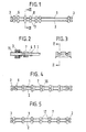
- the assembly unit shown in the figures consists essentially of two supply lines 1 and 2, which are preferably made of plastic and can have the same or different diameters.
- the lines 1 and 2 are connected at their ends with so-called plug-in couplings 3, which are intended to connect further connecting lines 14 and 15 (FIG. 8).
- the plug-in couplings 3 can be connected at the rear end to a connecting piece 4, on which the supply line 1 or 2 is plugged with a somewhat enlarged end piece 5 (FIG. 1). It is also possible to provide the plug-in coupling 3 at its rear end with a further plug-in coupling 6, into which the supply line 1 or 2 can be inserted directly (FIG. 4).
- the supply lines 1, 2 are also connected to one another by a large number of known line holders 7, which are provided with an integrated fastener part 8 for pressing the line holder 7 onto so-called plug bolts 9.
- These can be designed both as T-bolts and as threaded bolts, the preferred threaded bolts 9 being shown in the drawing (FIGS. 3, 9 and 10).
- Fastener parts for receiving threaded bolts are widely known, for. B. by EP no. 28 323 or DE-PS 34 06 934.
- the line holders 7 sit at irregular intervals on the supply lines 1 and 2. Only the two outer line holders 7 sit on the connecting piece 5 the plug-in couplings 4 in the place they need for later assembly on the threaded bolt 9.
- the assembly sequence for this assembly unit is shown schematically in FIGS. 6 to 10.
- FIG. 6 shows the assembly unit from the side, the line holders 7 having already been moved into their assembly position.
- the assembly unit is placed with the aligned line holders 7 on a lifting plate or beam 10 located next to the assembly line, corresponding recesses 11 being provided for the position-specific reception of the line holders 7.
- the positioning of the line holder can of course also be done by pins or any other suitable type.
- the prepared walking beam 10 is then placed in its place on the assembly line and raised from below against the vehicle body 13 by means of a lifting device 12 (FIGS. 7 and 9) until the line holders 7 with their fastening parts 8 are anchored on the threaded bolt 9 (FIG. 8 and 10). Finally, connecting lines 14 and 15 are inserted into the coupling pieces 3 in the direction of the arrow and the line assembly is finished.
- the line holder 7 can already be fixed immovably at the manufacturer at the position-determined locations on the supply lines 1 and 2. This is done in Figure 4 by attaching additional clamping springs 16, which can be connected to the line holder 7, or can be plugged onto its two sides.
- FIG. 5 Another possibility of axial fixing is indicated in FIG. 5.
- beads 17 are provided, which have either been applied beforehand in the factory during the line production, or have been generated by the manufacturer of the assembly unit after aligning the line holder 7, for example by pressing hot stamps or the like . It is advisable here to set the beads 17 in such a way that a small axial displacement of the line holder 7 on the lines 1 and 2 is possible, by an amount such as is required for tolerance compensation between the threaded bolts 9.
Landscapes
- Engineering & Computer Science (AREA)
- Mechanical Engineering (AREA)
- Automobile Manufacture Line, Endless Track Vehicle, Trailer (AREA)
- Clamps And Clips (AREA)
Applications Claiming Priority (2)
| Application Number | Priority Date | Filing Date | Title |
|---|---|---|---|
| DE19873705626 DE3705626A1 (de) | 1987-02-21 | 1987-02-21 | Montageeinheit zur befestigung von versorgungsleitungen an kraftfahrzeugen |
| DE3705626 | 1987-02-21 |
Publications (3)
| Publication Number | Publication Date |
|---|---|
| EP0283714A2 true EP0283714A2 (fr) | 1988-09-28 |
| EP0283714A3 EP0283714A3 (en) | 1989-02-22 |
| EP0283714B1 EP0283714B1 (fr) | 1990-08-22 |
Family
ID=6321501
Family Applications (1)
| Application Number | Title | Priority Date | Filing Date |
|---|---|---|---|
| EP88102344A Expired - Lifetime EP0283714B1 (fr) | 1987-02-21 | 1988-02-18 | Unité préassemblée pour la fixation de canalisations sur des véhicules automobiles |
Country Status (3)
| Country | Link |
|---|---|
| EP (1) | EP0283714B1 (fr) |
| DE (2) | DE3705626A1 (fr) |
| ES (1) | ES2016864B3 (fr) |
Cited By (2)
| Publication number | Priority date | Publication date | Assignee | Title |
|---|---|---|---|---|
| FR2640563A1 (fr) * | 1988-12-16 | 1990-06-22 | Peugeot | Appui de cric pour vehicule automobile |
| CN111807258A (zh) * | 2020-07-10 | 2020-10-23 | 临沂矿业集团菏泽煤电有限公司 | 一种托管梁更换辅助装置 |
Families Citing this family (7)
| Publication number | Priority date | Publication date | Assignee | Title |
|---|---|---|---|---|
| EP0316606B1 (fr) * | 1987-11-14 | 1991-12-11 | A. Raymond & Cie | Support pour la fixation des lignes d'alimentation des véhicules automobiles |
| DE4022173A1 (de) * | 1990-07-12 | 1992-01-23 | Tucker Gmbh | Befestigungsvorrichtung |
| US5161759A (en) * | 1991-06-17 | 1992-11-10 | Emhart, Inc. | Wire bundle retainer |
| DE4404879C2 (de) * | 1994-02-17 | 1997-04-10 | Technoflow Tube Systems Gmbh | Werkmäßig vorgefertigtes Fluidleitungssystem, welches zur Montage in ein Kraftfahrzeug im Zuge der automatischen Bandfertigung von typisierten Kraftfahrzeugen eingerichtet ist |
| DE19840136A1 (de) * | 1998-09-03 | 2000-03-09 | Volkswagen Ag | Halterungselement und Halterung für starre Leitungen in einem Fahrzeug |
| FR2812064B1 (fr) * | 2000-07-19 | 2003-01-03 | Renault | Dispositif de fixation d'element de cablage ou analogue sur materiau mou, notamment insonorisant pour voiture |
| FR2990387A1 (fr) * | 2012-05-09 | 2013-11-15 | Peugeot Citroen Automobiles Sa | Procede d'installation d'au moins une canalisation menagee sous une caisse d'un vehicule automobile |
Citations (2)
| Publication number | Priority date | Publication date | Assignee | Title |
|---|---|---|---|---|
| EP0028323A1 (fr) | 1979-11-06 | 1981-05-13 | Firma A. Raymond | Clip pour la fixation détachable d'éléments de construction sur une plaque support en utilisant des boulons taraudés |
| DE3406934C1 (de) | 1984-02-25 | 1985-09-05 | Fa. A. Raymond, 7850 Lörrach | Mutternartiges Befestigungselement |
Family Cites Families (3)
| Publication number | Priority date | Publication date | Assignee | Title |
|---|---|---|---|---|
| DE3236981A1 (de) * | 1982-10-06 | 1984-04-12 | Hans-Hellmut Dipl.-Ing. 2061 Sülfeld Ernst | Vorrichtung zum befestigen von rohren, insbesondere in fahrzeugen |
| DE3236983A1 (de) * | 1982-10-06 | 1984-04-12 | Hans-Hellmut Dipl.-Ing. 2061 Sülfeld Ernst | Vorrichtung zum befestigen von rohren, insbesondere in fahrzeugen |
| DE3602625C1 (de) * | 1986-01-29 | 1987-03-05 | Bayerische Motoren Werke Ag | Haltevorrichtung fuer mindestens eine Leitung,insbesondere eine Kraftstoffleitung an einem Kraftfahrzeug |
-
1987
- 1987-02-21 DE DE19873705626 patent/DE3705626A1/de not_active Withdrawn
-
1988
- 1988-02-18 ES ES88102344T patent/ES2016864B3/es not_active Expired - Lifetime
- 1988-02-18 EP EP88102344A patent/EP0283714B1/fr not_active Expired - Lifetime
- 1988-02-18 DE DE8888102344T patent/DE3860470D1/de not_active Expired - Fee Related
Patent Citations (2)
| Publication number | Priority date | Publication date | Assignee | Title |
|---|---|---|---|---|
| EP0028323A1 (fr) | 1979-11-06 | 1981-05-13 | Firma A. Raymond | Clip pour la fixation détachable d'éléments de construction sur une plaque support en utilisant des boulons taraudés |
| DE3406934C1 (de) | 1984-02-25 | 1985-09-05 | Fa. A. Raymond, 7850 Lörrach | Mutternartiges Befestigungselement |
Cited By (3)
| Publication number | Priority date | Publication date | Assignee | Title |
|---|---|---|---|---|
| FR2640563A1 (fr) * | 1988-12-16 | 1990-06-22 | Peugeot | Appui de cric pour vehicule automobile |
| EP0375509A1 (fr) * | 1988-12-16 | 1990-06-27 | Automobiles Peugeot | Dispositif de fixation de tubes rigides et de nappes souples sur un véhicule automobile |
| CN111807258A (zh) * | 2020-07-10 | 2020-10-23 | 临沂矿业集团菏泽煤电有限公司 | 一种托管梁更换辅助装置 |
Also Published As
| Publication number | Publication date |
|---|---|
| EP0283714A3 (en) | 1989-02-22 |
| EP0283714B1 (fr) | 1990-08-22 |
| DE3705626A1 (de) | 1988-09-01 |
| ES2016864B3 (es) | 1990-12-01 |
| DE3860470D1 (de) | 1990-09-27 |
Similar Documents
| Publication | Publication Date | Title |
|---|---|---|
| EP2125425B1 (fr) | Siège de véhicule et procédé de montage | |
| DE10018407A1 (de) | Karosserie eines Kraftfahrzeuges mit einem Sitzmodul | |
| DE10304278B4 (de) | Struktur zur Befestigung einer Anzeigeeinheit an einer Instrumentenkonsole eines Automobils | |
| DE3034729A1 (de) | Befestigungsvorrichtung fuer verkleidungsplatten | |
| EP0550742B1 (fr) | Ensemble d'actionnement des freins pour vehicules a moteur | |
| EP0283714B1 (fr) | Unité préassemblée pour la fixation de canalisations sur des véhicules automobiles | |
| EP2730456B1 (fr) | Entraînement d'un dispositif de réglage de siège pour véhicules automobiles | |
| EP3374234B1 (fr) | Système de fixation | |
| DE69523357T2 (de) | Vorrichtung und Verfahren zur Montage von Motorfahrzeugen | |
| DE102009010296A1 (de) | Verbindungsanordnung eines Anbauteils an einem Karosseriebauteil | |
| DE2601546C3 (de) | Klemmhülse zum Befestigen einer Aufnahmebuchse für einen Zigarrenanzünder am Armaturenbrett von Kraftfahrzeugen | |
| EP0412418B1 (fr) | Bouton de demande d'arrêt | |
| DE102020000491A1 (de) | Haltevorrichtung für Batterien eines zumindest teilweise elektrisch betriebenen Kraftfahrzeugs | |
| DE19741551A1 (de) | Verbindungsanordnung zwischen Karosserieträgern und vormontierten Baugruppen | |
| DE4321303C1 (de) | Vorrichtung zum Befestigen eines Verkleidungsteiles an einem Karosserieteil | |
| DE29920025U1 (de) | Vorrichtung zur Befestigung eines Gassackmoduls an einem Lenkrad | |
| DE19832418B4 (de) | Karosseriebauteil mit einem Zentrierbolzen und Verfahren zur Reparatur eines solchen | |
| EP1467432A1 (fr) | Adaptateur de contact pour faire un contact à une structure d'antenne pour une voiture | |
| DE10305190B3 (de) | Gehäuse zum Anbringen an einem Fahrzeugbauteil | |
| DE102019205524A1 (de) | Befestigungsvorrichtung für ein Kraftfahrzeug, Kraftfahrzeug mit einer Befestigungsvorrichtung und Verfahren zur Montage einer Befestigungsvorrichtung | |
| DE102019135321B4 (de) | Haltervorrichtung zu Befestigung einer Leitung an einem Schienenfahrzeug | |
| EP0297218A2 (fr) | Raccord enfichable | |
| DE102009004553A1 (de) | Verkleidungspaneel-Haltesystem | |
| DE10222065B4 (de) | Halterungsklammer zur Festlegung eines Leitungsstranges in einem Fahrzeug | |
| DE10334734A1 (de) | Befestigungsvorrichtung mit Toleranzausgleich |
Legal Events
| Date | Code | Title | Description |
|---|---|---|---|
| PUAI | Public reference made under article 153(3) epc to a published international application that has entered the european phase |
Free format text: ORIGINAL CODE: 0009012 |
|
| AK | Designated contracting states |
Kind code of ref document: A2 Designated state(s): DE ES FR GB IT NL SE |
|
| RBV | Designated contracting states (corrected) |
Designated state(s): DE ES FR GB IT NL SE |
|
| PUAL | Search report despatched |
Free format text: ORIGINAL CODE: 0009013 |
|
| AK | Designated contracting states |
Kind code of ref document: A3 Designated state(s): DE ES FR GB IT NL SE |
|
| RHK1 | Main classification (correction) |
Ipc: B60R 1/08 |
|
| 17P | Request for examination filed |
Effective date: 19890706 |
|
| 17Q | First examination report despatched |
Effective date: 19891012 |
|
| GRAA | (expected) grant |
Free format text: ORIGINAL CODE: 0009210 |
|
| AK | Designated contracting states |
Kind code of ref document: B1 Designated state(s): DE ES FR GB IT NL SE |
|
| ITF | It: translation for a ep patent filed | ||
| REF | Corresponds to: |
Ref document number: 3860470 Country of ref document: DE Date of ref document: 19900927 |
|
| GBT | Gb: translation of ep patent filed (gb section 77(6)(a)/1977) | ||
| RAP2 | Party data changed (patent owner data changed or rights of a patent transferred) |
Owner name: A. RAYMOND KG |
|
| ET | Fr: translation filed | ||
| NLT2 | Nl: modifications (of names), taken from the european patent patent bulletin |
Owner name: A. RAYMOND KG TE LOERRACH, BONDSREPUBLIEK DUITSLAN |
|
| NLS | Nl: assignments of ep-patents |
Owner name: A. RAYMOND KG TE LOERRACH, BONDSREPUBLIEK DUITSLAN |
|
| PLBI | Opposition filed |
Free format text: ORIGINAL CODE: 0009260 |
|
| 26 | Opposition filed |
Opponent name: BAYERISCHE MOTOREN WERKE AKTIENGESELLSCHAFT Effective date: 19910517 |
|
| NLR1 | Nl: opposition has been filed with the epo |
Opponent name: BAYERISCHE MOTOREN WERKE AKTIENGESELLSCHAFT. |
|
| PLBM | Termination of opposition procedure: date of legal effect published |
Free format text: ORIGINAL CODE: 0009276 |
|
| STAA | Information on the status of an ep patent application or granted ep patent |
Free format text: STATUS: OPPOSITION PROCEDURE CLOSED |
|
| ITTA | It: last paid annual fee | ||
| 27C | Opposition proceedings terminated |
Effective date: 19911114 |
|
| NLR2 | Nl: decision of opposition | ||
| EAL | Se: european patent in force in sweden |
Ref document number: 88102344.4 |
|
| REG | Reference to a national code |
Ref country code: GB Ref legal event code: 732E |
|
| PGFP | Annual fee paid to national office [announced via postgrant information from national office to epo] |
Ref country code: FR Payment date: 20010227 Year of fee payment: 14 |
|
| REG | Reference to a national code |
Ref country code: GB Ref legal event code: IF02 |
|
| PG25 | Lapsed in a contracting state [announced via postgrant information from national office to epo] |
Ref country code: FR Free format text: LAPSE BECAUSE OF NON-PAYMENT OF DUE FEES Effective date: 20021031 |
|
| REG | Reference to a national code |
Ref country code: FR Ref legal event code: ST |
|
| PGFP | Annual fee paid to national office [announced via postgrant information from national office to epo] |
Ref country code: ES Payment date: 20030127 Year of fee payment: 16 |
|
| PGFP | Annual fee paid to national office [announced via postgrant information from national office to epo] |
Ref country code: GB Payment date: 20030213 Year of fee payment: 16 |
|
| PGFP | Annual fee paid to national office [announced via postgrant information from national office to epo] |
Ref country code: NL Payment date: 20030228 Year of fee payment: 16 |
|
| PGFP | Annual fee paid to national office [announced via postgrant information from national office to epo] |
Ref country code: DE Payment date: 20040128 Year of fee payment: 17 |
|
| PGFP | Annual fee paid to national office [announced via postgrant information from national office to epo] |
Ref country code: SE Payment date: 20040216 Year of fee payment: 17 |
|
| PG25 | Lapsed in a contracting state [announced via postgrant information from national office to epo] |
Ref country code: GB Free format text: LAPSE BECAUSE OF NON-PAYMENT OF DUE FEES Effective date: 20040218 |
|
| PG25 | Lapsed in a contracting state [announced via postgrant information from national office to epo] |
Ref country code: ES Free format text: LAPSE BECAUSE OF NON-PAYMENT OF DUE FEES Effective date: 20040219 |
|
| PG25 | Lapsed in a contracting state [announced via postgrant information from national office to epo] |
Ref country code: NL Free format text: LAPSE BECAUSE OF NON-PAYMENT OF DUE FEES Effective date: 20040901 |
|
| GBPC | Gb: european patent ceased through non-payment of renewal fee |
Effective date: 20040218 |
|
| NLV4 | Nl: lapsed or anulled due to non-payment of the annual fee |
Effective date: 20040901 |
|
| PG25 | Lapsed in a contracting state [announced via postgrant information from national office to epo] |
Ref country code: IT Free format text: LAPSE BECAUSE OF NON-PAYMENT OF DUE FEES;WARNING: LAPSES OF ITALIAN PATENTS WITH EFFECTIVE DATE BEFORE 2007 MAY HAVE OCCURRED AT ANY TIME BEFORE 2007. THE CORRECT EFFECTIVE DATE MAY BE DIFFERENT FROM THE ONE RECORDED. Effective date: 20050218 |
|
| PG25 | Lapsed in a contracting state [announced via postgrant information from national office to epo] |
Ref country code: SE Free format text: LAPSE BECAUSE OF NON-PAYMENT OF DUE FEES Effective date: 20050219 |
|
| REG | Reference to a national code |
Ref country code: ES Ref legal event code: FD2A Effective date: 20040219 |
|
| PG25 | Lapsed in a contracting state [announced via postgrant information from national office to epo] |
Ref country code: DE Free format text: LAPSE BECAUSE OF NON-PAYMENT OF DUE FEES Effective date: 20050901 |
|
| EUG | Se: european patent has lapsed |