EP0283880A1 - Elément de ressort commandé électriquement - Google Patents
Elément de ressort commandé électriquement Download PDFInfo
- Publication number
- EP0283880A1 EP0283880A1 EP88103936A EP88103936A EP0283880A1 EP 0283880 A1 EP0283880 A1 EP 0283880A1 EP 88103936 A EP88103936 A EP 88103936A EP 88103936 A EP88103936 A EP 88103936A EP 0283880 A1 EP0283880 A1 EP 0283880A1
- Authority
- EP
- European Patent Office
- Prior art keywords
- plunger
- spring element
- electrically controlled
- elements
- basic
- Prior art date
- Legal status (The legal status is an assumption and is not a legal conclusion. Google has not performed a legal analysis and makes no representation as to the accuracy of the status listed.)
- Granted
Links
- 230000005415 magnetization Effects 0.000 claims abstract description 23
- 239000000463 material Substances 0.000 claims abstract description 17
- 230000005284 excitation Effects 0.000 claims abstract description 15
- 230000005540 biological transmission Effects 0.000 claims abstract description 3
- 206010001497 Agitation Diseases 0.000 claims description 2
- 229910052729 chemical element Inorganic materials 0.000 abstract description 4
- 229910001329 Terfenol-D Inorganic materials 0.000 abstract description 2
- 229910045601 alloy Inorganic materials 0.000 description 8
- 239000000956 alloy Substances 0.000 description 8
- 230000009021 linear effect Effects 0.000 description 8
- 229910052761 rare earth metal Inorganic materials 0.000 description 6
- 150000002910 rare earth metals Chemical class 0.000 description 6
- 238000000034 method Methods 0.000 description 5
- 230000004075 alteration Effects 0.000 description 4
- 230000001419 dependent effect Effects 0.000 description 4
- XEEYBQQBJWHFJM-UHFFFAOYSA-N Iron Chemical compound [Fe] XEEYBQQBJWHFJM-UHFFFAOYSA-N 0.000 description 3
- PXHVJJICTQNCMI-UHFFFAOYSA-N Nickel Chemical compound [Ni] PXHVJJICTQNCMI-UHFFFAOYSA-N 0.000 description 3
- 238000010276 construction Methods 0.000 description 3
- 230000000694 effects Effects 0.000 description 3
- 230000008859 change Effects 0.000 description 2
- 230000004907 flux Effects 0.000 description 2
- 238000004519 manufacturing process Methods 0.000 description 2
- 230000009347 mechanical transmission Effects 0.000 description 2
- 229910052751 metal Inorganic materials 0.000 description 2
- 239000002184 metal Substances 0.000 description 2
- 239000007769 metal material Substances 0.000 description 2
- 239000008188 pellet Substances 0.000 description 2
- 230000001052 transient effect Effects 0.000 description 2
- 229910052692 Dysprosium Inorganic materials 0.000 description 1
- 229910052691 Erbium Inorganic materials 0.000 description 1
- 229910052689 Holmium Inorganic materials 0.000 description 1
- 229910052772 Samarium Inorganic materials 0.000 description 1
- XUIMIQQOPSSXEZ-UHFFFAOYSA-N Silicon Chemical compound [Si] XUIMIQQOPSSXEZ-UHFFFAOYSA-N 0.000 description 1
- 229910052771 Terbium Inorganic materials 0.000 description 1
- 239000011149 active material Substances 0.000 description 1
- 238000005275 alloying Methods 0.000 description 1
- 238000011161 development Methods 0.000 description 1
- 230000018109 developmental process Effects 0.000 description 1
- KBQHZAAAGSGFKK-UHFFFAOYSA-N dysprosium atom Chemical compound [Dy] KBQHZAAAGSGFKK-UHFFFAOYSA-N 0.000 description 1
- UYAHIZSMUZPPFV-UHFFFAOYSA-N erbium Chemical compound [Er] UYAHIZSMUZPPFV-UHFFFAOYSA-N 0.000 description 1
- 239000012530 fluid Substances 0.000 description 1
- KJZYNXUDTRRSPN-UHFFFAOYSA-N holmium atom Chemical compound [Ho] KJZYNXUDTRRSPN-UHFFFAOYSA-N 0.000 description 1
- 229910052742 iron Inorganic materials 0.000 description 1
- 238000002955 isolation Methods 0.000 description 1
- 238000003475 lamination Methods 0.000 description 1
- 238000011068 loading method Methods 0.000 description 1
- 239000000696 magnetic material Substances 0.000 description 1
- 239000012528 membrane Substances 0.000 description 1
- 150000002739 metals Chemical class 0.000 description 1
- 239000000203 mixture Substances 0.000 description 1
- 229910052759 nickel Inorganic materials 0.000 description 1
- 239000003921 oil Substances 0.000 description 1
- 230000036961 partial effect Effects 0.000 description 1
- 230000035699 permeability Effects 0.000 description 1
- 230000000704 physical effect Effects 0.000 description 1
- 230000008569 process Effects 0.000 description 1
- KZUNJOHGWZRPMI-UHFFFAOYSA-N samarium atom Chemical compound [Sm] KZUNJOHGWZRPMI-UHFFFAOYSA-N 0.000 description 1
- 229910052710 silicon Inorganic materials 0.000 description 1
- 239000010703 silicon Substances 0.000 description 1
- 230000003068 static effect Effects 0.000 description 1
- 239000000725 suspension Substances 0.000 description 1
- 230000001360 synchronised effect Effects 0.000 description 1
- GZCRRIHWUXGPOV-UHFFFAOYSA-N terbium atom Chemical compound [Tb] GZCRRIHWUXGPOV-UHFFFAOYSA-N 0.000 description 1
- 238000004804 winding Methods 0.000 description 1
Images


Classifications
-
- F—MECHANICAL ENGINEERING; LIGHTING; HEATING; WEAPONS; BLASTING
- F16—ENGINEERING ELEMENTS AND UNITS; GENERAL MEASURES FOR PRODUCING AND MAINTAINING EFFECTIVE FUNCTIONING OF MACHINES OR INSTALLATIONS; THERMAL INSULATION IN GENERAL
- F16F—SPRINGS; SHOCK-ABSORBERS; MEANS FOR DAMPING VIBRATION
- F16F6/00—Magnetic springs; Fluid magnetic springs, i.e. magnetic spring combined with a fluid
-
- H—ELECTRICITY
- H10—SEMICONDUCTOR DEVICES; ELECTRIC SOLID-STATE DEVICES NOT OTHERWISE PROVIDED FOR
- H10N—ELECTRIC SOLID-STATE DEVICES NOT OTHERWISE PROVIDED FOR
- H10N35/00—Magnetostrictive devices
Definitions
- the invention relates to an electrically controlled spring element according to the precharacterising part of Claim 1.
- an electrically controlled spring element can be specially designed to provide it with extremely good frequency properties. This enables it to be used as basic element in equipment for vibration-free suspension of extremely sensitive instruments, for instance, vibration-free mechanical transmission, as active mechanical moderator or actuator, controllable inductance, electromechanical transformer, etc.
- the main and essential difference between a passive, conventional spring element, and an electrically controllable spring element resides in the property of the latter that its spring constant, spring force and stretch can all be electrically controlled.
- the spring element can be caused within an extremely short time, in the region of 50 ms, to behave as a pre-stressed, mechanically passive spring element. Thanks to the good frequency properties the element can be designed with, it can also be altered in a very short time from one static, spring-force state into another and can thus also respond very well to dynamic electric control.
- US-A-4 378 258 shows a method of converting magnetic energy into mechanical energy, in which the mechanical energy appears in a change in the dimensions of a special alloy caused by a change in the magnetic field.
- These particular alloys have now been used in several practical applications, e.g. in the form of a SONAR, see US-A-4 438 509, and in valves, see US-A-4 158 368.
- the rare earth metals are generally expensive. Furthermore, the production of materials containing these alloys entails relatively complicated processes. Intensive research has therefore been carried on to develop alloys with optimal data both from the cost and the manufacturing aspects.
- the best composition discovered so far consists of Tb 0.27 DY 0.73 Fe 1.9 , and the alloy has been called TERFENOL-D.
- the material is currently manufactured in a limited number of places in the world and is supplied in the form of cylindrical rods having a diameter of about 6 to 40 mm and a length of up to about 300 mm.
- the invention aims at developing an electrically controlled spring element of the above-mentioned kind in which the necessary mechanical prestressing which is required to avoid tensile strain in the magnetostrictive material is provided in a very economical way without the need for excess magnetic energy.
- a further object of the invention is to design an electrically controlled spring element that exhibits a considerably magnified stretch in comparison to the stretch obtainable in the proper magnetostrictive material.
- the invention suggests an electrically controlled spring element according to the introductory part of Claim 1, which is characterized by the features of the characterizing part of Claim 1.
- Figure 1 the relative linear expansion ⁇ l/l (mm/m) is shown for a T-rod which is subjected to a magnetizing magnetic field strength H (A/m) along the symmetry axis of the rod.
- the graph shows how the linear expansion is dependent on the mechanical stress (MPa) applied on the T-rod.
- an electrically controlled spring element In an electrically controlled spring element according to the invention it is the mechanical properties which are utilized more in isolation, but of course intimately associated with the linear alterations in the T-rod.
- the alteration in length which can be obtained at various magnetization conditions of the highly magnetostrictive materials means that the stretch range, which may be up to about 100 ⁇ m, will in many applications be insufficient in a spring element based solely on the linear expansion of a T-rod.
- a spring element according to the invention therefore also includes a mechanical transmission between the highly magnetostrictive material and the mechanical load, in the form of a mechanical transformer permitting a considerably increased stretch range.
- the magnetostriction is dependent on the magnetizing field strength H. If the magnetization in a quasi-stationary state is to be proportional to an applied time-varying magnetization, therefore, the T-rod must be premagnetized, preferably by means of permanent magnets. According to a known method, e.g. described in WO 86/03888, this can be achieved by dividing the T-rod in axial direction into a number of pellets between which permanent magnets are placed, in order to ensure a magnetization distributed as uniformly as possible.
- various forms of lamination may be advisable, such as dividing the T-rod axially into a number of straight lamina of substantially equal width, by slicing the T-rod as shown in WO 86/03888, or by producing a spiral air gap by means of spark treating.
- a correspondingly large dynamic magnetizing field strength H is also required.
- the excitation coil surrounding the T-rod shall be able to generate this.
- the dynamic magnetization can be effected in conventional manner by increasing the supply voltage at increasing frequency.
- Another method might be the use of a coil system consisting of a number of coaxial, concentric coils supplied via galvanically separated, frequency-selecting amplifiers in such a way that the innermost coil is supplied by high-frequency components and the outermost coil is connected to an amplifier step with low frequency components.
- T-rod the tensile strength of a T-rod is considerably lower than its compressive strength.
- Mechanical pre-stressing is thus also necessary for T-rods under strong mechanical and electrical loads, to prevent them from being subjected to tensile stress.
- the mechanical pre-stressing required to prevent the occurrence of tensile stress in the T-rod, in the case of transient magnetic excitation and considerable mechanical load, is considerably greater than the pre-stressing required when taking into consideration only the selection of optimum operating point.
- Characteristic of the invention is that two such elementary elements A and B comprised in Figure 4 form an electrically controlled so-called "basic spring element" (AB).
- the elementary elements are mounted in a frame 1, the rods TA and TB being aligned with their axial centre lines and being separated by an intermediate transmission element with a power output 2.
- Pre-magnetization is suitably effected by dividing the T-rods into axially aligned pellets with permanent magnets inserted between them, indicated symbolically in Figure 4 as PA and PB.
- the excitation coils are designated 3 and 4.
- the magnetization circuits for the two elements should be spaced such that they do not noticeably influence each other.
- pre-stressing is effected by mechanically counter-connecting the two elementary elements comprised in the basic spring element. This can be achieved by ensuring that the magnetic orientation of the pre-magnetization and the excitation coils are always directed in a certain manner, i.e. the external electrically controlled magnetization must always be directed in the same direction as the pre-magnetization in one element and always directed opposite to the pre-magnetization direction in the other element.
- the external electrically controlled magnetization must always be directed in the same direction as the pre-magnetization in one element and always directed opposite to the pre-magnetization direction in the other element.
- magnetization is harmonious and the coils are otherwise identical, they may suitably be connected in series.
- the elementary elements may be supplied from different sources, mutually synchronized. Control is increased by this arrangement both because the resonance frequency of the system can be controlled and because no unnecessary energy is utilized to stress springs, as is the case in the state of the art when passive springs are used in strong transient magnetization. As explained, this is because the material must be protected against tensile stress by considerably over-dimensioned, mechanical pre-stressing. Furthermore, if passive springs are used for pre-stressing, they will also serve as pull-off springs for the previously mentioned simple spring elements, as e.g. sonars, etc.
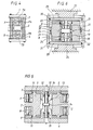
- an electrically controlled spring element according to the invention includes a mechanical transformer composed in principle as a differential plunger arrangement in order to increase the stretch range further than is permitted by the T-rod.
- This transformer and two electrically controlled basic spring elements AB mechanically counter-connected as shown in Figure 4 constitute a preferred embodiment of a complete, electrically controlled spring element according to the invention and will be described with reference to Figure 5.
- the complete spring element consists of a body with a central symmetry plane as shown in Figure 5. In a preferred embodiment the body is cylindrical, with central cylindrical openings in the end surfaces for power outputs.
- the construction consists of an upper lid 5, a lower lid 6 and two rings 7 and 8 abutting the inner side of the upper and lower lids, respectively.
- the rings may also constitute an integral part of each lid.
- the construction is made up of two complete basic spring elements according to Figure 4. Each of these is located between the lids and on opposite sides and equidistant from the symmetry axis (mid-line in Figure 5) of the symmetry plane. Lids, rings and basic spring elements are held together by a screw arrangement, not shown. Inside the construction is a first plunger 9 having two diametrically located power outputs 2, located centrally and extending radially outwards from the plunger, corresponding to the power outputs on the basic spring element according to Figure 4.
- This first plunger thus moves synchronously with the upward and downward movement of the T-rods which, as mentioned above, in practice move maximally 50-100 ⁇ m.
- the upward and downward movement of this plunger is controlled by the inner surface of the rings 7 and 8 and a seal is located in grooves in plunger and rings in the form of low-friction seals 10 and 11, permitting the upward and downward movement of the plunger.
- This first plunger has a central, cylindrical through-opening with a lining 12, inside which a second plunger 13 can move.
- the second plunger is sealed by a piston ring 14 to the lining of the first plunger.
- a tapped pin 15 runs centrally through the second plunger and is guided by said central openings in the lids 5 and 6. Seals in the form of piston rings 16 and 17 are also provided between each lid and the central pin.
- the free, sealed space defined by the top of the first plunger, the inner surface of lid 5, the lining 12, the central pin and the top of the second plunger is filled with a low-compressive medium having low internal friction, e.g. silicon oil, under a certain over-pressure.
- the corresponding space in the lower half of the complete spring element is also filled with the same medium under the same over-pressure.
- the second plunger with its central pin will move in the opposite direction to the first plunger with an amplitude/stretch gain corresponding to the ratio between the active hydraulic areas of the two plungers.
- an active area ratio of 200 which, with a maximum movement of about 100 ⁇ m of the first plunger, would give a movement of 20 mm for the second plunger including its central pin.
- the available force on the central pin will be a corresponding number of times lower than the force on the output shoulders 2.
- An extremely simple way of influencing the stretch increase or the tensile or compressive force is to alter the ratio between the active areas of the plungers. This can be done, for instance, by altering the inner diameter of the lining ring 12 and thus the outer diameter of the second plunger.
- the number of pairs of mechanically connected electrically controlled basic spring elements according to Figure 4 may be increased.
- the basic spring elements are preferably located in a symmetrical or mirror-symmetrical configuration.
- the shape of the complete spring element need not necessarily be cylindrical.
- the lids, and thus the outer contours, may have elliptical, rectangular, quadratic or some other shape depending on the application.
- FIG. 6 An electrically controlled spring element having only one basic spring element AB according to Figure 4 is also possible.
- An embodiment of this kind with substantially the same principle for the mechanical transformer is shown in Figure 6.
- the basic spring element AB is located centrally.
- the power outputs 2 are in engagement with a plunger 18 surrounding the basic spring element and controlled by two sleeves 19 and 20.
- the plunger is sealed from the outer spaces 21 and 22, filled with low-compressive medium, by means of low-friction seals 23 and 24.
- the piston 18 is provided with an outer lining ring 25 against which an outer plunger 26 can move.
- This plunger constitutes an integral part of an outer, tubular casing 27 from which power output occurs from the electrically controlled spring element.
- the tubular casing is guided by the two lids 28 and 29.
- the two spaces 21 and 22 filled with low-compressive medium are provided with seals 30 and 31 between the casing and respective lids, and a seal 32 between the spaces 21 and 22.
- Other external positioning means are supports 33 and 34.
- the plungers 18 and 26 move in opposite directions and the amplitude/stretch gain is dependent on the ratio between the hydraulic areas of the plungers.
Landscapes
- Engineering & Computer Science (AREA)
- General Engineering & Computer Science (AREA)
- Mechanical Engineering (AREA)
- Springs (AREA)
- Registering, Tensioning, Guiding Webs, And Rollers Therefor (AREA)
- Surgical Instruments (AREA)
- Dry Shavers And Clippers (AREA)
- General Electrical Machinery Utilizing Piezoelectricity, Electrostriction Or Magnetostriction (AREA)
Applications Claiming Priority (2)
| Application Number | Priority Date | Filing Date | Title |
|---|---|---|---|
| SE8701138A SE8701138D0 (sv) | 1987-03-19 | 1987-03-19 | Elektriskt styrt fjederelement |
| SE8701138 | 1987-03-19 |
Publications (2)
| Publication Number | Publication Date |
|---|---|
| EP0283880A1 true EP0283880A1 (fr) | 1988-09-28 |
| EP0283880B1 EP0283880B1 (fr) | 1993-01-13 |
Family
ID=20367915
Family Applications (1)
| Application Number | Title | Priority Date | Filing Date |
|---|---|---|---|
| EP88103936A Expired - Lifetime EP0283880B1 (fr) | 1987-03-19 | 1988-03-12 | Elément de ressort commandé électriquement |
Country Status (6)
| Country | Link |
|---|---|
| US (1) | US4802660A (fr) |
| EP (1) | EP0283880B1 (fr) |
| JP (1) | JPS63254243A (fr) |
| DE (1) | DE3877392T2 (fr) |
| NO (1) | NO178710C (fr) |
| SE (1) | SE8701138D0 (fr) |
Cited By (6)
| Publication number | Priority date | Publication date | Assignee | Title |
|---|---|---|---|---|
| EP0379075A1 (fr) * | 1989-01-16 | 1990-07-25 | Asea Brown Boveri Ab | Circuit magnétique |
| EP0425954A1 (fr) * | 1989-10-31 | 1991-05-08 | Abb Atom Ab | Dispositif pour transmission du mouvement et force de compression |
| EP0443873A1 (fr) * | 1990-02-23 | 1991-08-28 | Kabushiki Kaisha Toshiba | Organe d'actionnement magnétostrictif |
| US5052529A (en) * | 1989-03-16 | 1991-10-01 | Topexpress Limited | Active control of vibration |
| US5238232A (en) * | 1991-10-09 | 1993-08-24 | Honda Giken Kogyo Kabushiki Kaisha | Self-expanding mount |
| WO2009044180A1 (fr) * | 2007-10-03 | 2009-04-09 | Feonic Plc | Actionneur magnetostrictif |
Families Citing this family (10)
| Publication number | Priority date | Publication date | Assignee | Title |
|---|---|---|---|---|
| SE466467B (sv) * | 1987-12-10 | 1992-02-17 | Asea Atom Ab | Vaetskepump driven av element av ett jaettemagnetostriktivt material |
| SE464933B (sv) * | 1989-12-21 | 1991-07-01 | Wabco Holdings Sab | Kraftaktuatorarrangemang |
| DE4032555A1 (de) * | 1990-10-13 | 1992-04-16 | Teves Gmbh Alfred | Elektromagnetisch betaetigte hydraulische pumpe |
| WO1997038242A1 (fr) * | 1996-04-08 | 1997-10-16 | Delta Tooling Co., Ltd. | Ressort magnetique dote de caracteristiques d'amortissement et mecanisme vibratoire equipe de ce type de ressort |
| JP3725272B2 (ja) * | 1996-12-27 | 2005-12-07 | 株式会社デルタツーリング | 振動発生機構 |
| JPH1130274A (ja) * | 1997-05-15 | 1999-02-02 | Delta Tsuuring:Kk | 磁気バネを有する振動機構 |
| KR100281474B1 (ko) | 1997-05-16 | 2001-02-01 | 후지타 히토시 | 자기스프링을구비한에너지출력기구 |
| US20070210527A1 (en) * | 2006-03-01 | 2007-09-13 | Yoshio Yano | Seal device |
| CN104976263B (zh) * | 2015-05-14 | 2017-03-15 | 上海交通大学 | 一种对称型电磁作动器 |
| CN105840707B (zh) * | 2016-06-20 | 2017-10-24 | 中国舰船研究设计中心 | 船用电磁作动器 |
Citations (4)
| Publication number | Priority date | Publication date | Assignee | Title |
|---|---|---|---|---|
| US4438509A (en) * | 1981-05-18 | 1984-03-20 | Raytheon Company | Transducer with tensioned-wire precompression |
| WO1985002084A1 (fr) * | 1983-10-31 | 1985-05-09 | Gould Inc. | Transducteur de sons a basse frequence |
| WO1986003888A1 (fr) * | 1984-12-19 | 1986-07-03 | Gould Inc. | Transducteur flextensionnel en terres rares |
| GB2174863A (en) * | 1985-05-10 | 1986-11-12 | Raytheon Co | Permanent magnet biased magnetostrictive transducer |
Family Cites Families (5)
| Publication number | Priority date | Publication date | Assignee | Title |
|---|---|---|---|---|
| US4378258A (en) * | 1972-03-16 | 1983-03-29 | The United States Of America As Represented By The Secretary Of The Navy | Conversion between magnetic energy and mechanical energy |
| US4158368A (en) * | 1976-05-12 | 1979-06-19 | The United States Of America As Represented By The Secretary Of The Navy | Magnetostrictive transducer |
| US4308474A (en) * | 1979-11-14 | 1981-12-29 | The United States Of America As Represented By The Secretary Of The Navy | Rare earth-iron magnetostrictive materials and devices using these materials |
| US4642802A (en) * | 1984-12-14 | 1987-02-10 | Raytheon Company | Elimination of magnetic biasing using magnetostrictive materials of opposite strain |
| US4845450A (en) * | 1986-06-02 | 1989-07-04 | Raytheon Company | Self-biased modular magnetostrictive driver and transducer |
-
1987
- 1987-03-19 SE SE8701138A patent/SE8701138D0/xx unknown
-
1988
- 1988-03-12 EP EP88103936A patent/EP0283880B1/fr not_active Expired - Lifetime
- 1988-03-12 DE DE8888103936T patent/DE3877392T2/de not_active Expired - Fee Related
- 1988-03-14 NO NO881123A patent/NO178710C/no not_active IP Right Cessation
- 1988-03-15 US US07/168,417 patent/US4802660A/en not_active Expired - Lifetime
- 1988-03-17 JP JP63064642A patent/JPS63254243A/ja active Pending
Patent Citations (4)
| Publication number | Priority date | Publication date | Assignee | Title |
|---|---|---|---|---|
| US4438509A (en) * | 1981-05-18 | 1984-03-20 | Raytheon Company | Transducer with tensioned-wire precompression |
| WO1985002084A1 (fr) * | 1983-10-31 | 1985-05-09 | Gould Inc. | Transducteur de sons a basse frequence |
| WO1986003888A1 (fr) * | 1984-12-19 | 1986-07-03 | Gould Inc. | Transducteur flextensionnel en terres rares |
| GB2174863A (en) * | 1985-05-10 | 1986-11-12 | Raytheon Co | Permanent magnet biased magnetostrictive transducer |
Cited By (9)
| Publication number | Priority date | Publication date | Assignee | Title |
|---|---|---|---|---|
| EP0379075A1 (fr) * | 1989-01-16 | 1990-07-25 | Asea Brown Boveri Ab | Circuit magnétique |
| US5052529A (en) * | 1989-03-16 | 1991-10-01 | Topexpress Limited | Active control of vibration |
| EP0425954A1 (fr) * | 1989-10-31 | 1991-05-08 | Abb Atom Ab | Dispositif pour transmission du mouvement et force de compression |
| EP0443873A1 (fr) * | 1990-02-23 | 1991-08-28 | Kabushiki Kaisha Toshiba | Organe d'actionnement magnétostrictif |
| US5238232A (en) * | 1991-10-09 | 1993-08-24 | Honda Giken Kogyo Kabushiki Kaisha | Self-expanding mount |
| EP0536761B1 (fr) * | 1991-10-09 | 1996-02-07 | Honda Giken Kogyo Kabushiki Kaisha | Support auto-dilatant pour limiter la transmission de vibration d'une source de vibration à une embase |
| WO2009044180A1 (fr) * | 2007-10-03 | 2009-04-09 | Feonic Plc | Actionneur magnetostrictif |
| US8471432B2 (en) | 2007-10-03 | 2013-06-25 | Feonic Plc | Magnetostrictive actuator |
| CN101821871B (zh) * | 2007-10-03 | 2013-11-13 | Feonic公共有限公司 | 磁致伸缩致动器 |
Also Published As
| Publication number | Publication date |
|---|---|
| NO881123L (no) | 1988-09-20 |
| SE8701138D0 (sv) | 1987-03-19 |
| DE3877392D1 (de) | 1993-02-25 |
| DE3877392T2 (de) | 1993-08-19 |
| JPS63254243A (ja) | 1988-10-20 |
| US4802660A (en) | 1989-02-07 |
| EP0283880B1 (fr) | 1993-01-13 |
| NO178710B (no) | 1996-02-05 |
| NO881123D0 (no) | 1988-03-14 |
| NO178710C (no) | 1996-05-15 |
Similar Documents
| Publication | Publication Date | Title |
|---|---|---|
| EP0283880B1 (fr) | Elément de ressort commandé électriquement | |
| EP0838095B1 (fr) | Procede de production de mouvement et de force par commande de l'orientation de la structure jumelee d'un materiau, et ses utilisations | |
| US6037682A (en) | Integrated multi-mode transducer and method | |
| DE3785252T2 (de) | Magnetostriktives antriebsmodul. | |
| Jenner et al. | Actuation and transduction by giant magnetostrictive alloys | |
| JP2006521198A (ja) | 磁歪性材料を含む減衰・作動装置、振動減衰デバイス、および上記装置の使用方法 | |
| JP2756471B2 (ja) | ラジアル配向磁石の製造方法およびラジアル配向磁石 | |
| EP0379075B1 (fr) | Circuit magnétique | |
| US5357232A (en) | Magnetostrictive element | |
| CN1320737C (zh) | 自动对中线性电动机和发电机 | |
| US6300855B1 (en) | Hysteresis reduction in giant magnetostrictive materials | |
| CN111541352A (zh) | 包括气隙内的可移位铁磁构件的螺线管 | |
| JP3315235B2 (ja) | 磁歪式アクチュエータ | |
| Goodfriend et al. | High-force high-strain wide-bandwidth linear actuator using the magnetostrictive material Terfenol-D | |
| US10153682B2 (en) | Self-centering electromagnetic transducers | |
| US20240031751A1 (en) | Loudspeakers | |
| US3439199A (en) | Magnetostrictive unit | |
| JP3332125B2 (ja) | 磁歪式アクチュエータ | |
| US20200188956A1 (en) | Vibration source | |
| JPH04229085A (ja) | 磁歪式アクチュエータ | |
| Hall et al. | Broadband performance of a magnetostrictive shaker | |
| Ubaidillah et al. | Design and fabrication of magnetorheological elastomer vibration isolator/Ubaidillah...[et al.] | |
| Yang et al. | Low-frequency Vibration Shaker with High Output Force Based on Giant Magnetostrictive Actuator | |
| Humali | Influence of Shaft Material Magnetic Characteristics on Electromag-netic Actuator | |
| JP3131090U (ja) | 磁歪素子アクチュエータ |
Legal Events
| Date | Code | Title | Description |
|---|---|---|---|
| PUAI | Public reference made under article 153(3) epc to a published international application that has entered the european phase |
Free format text: ORIGINAL CODE: 0009012 |
|
| AK | Designated contracting states |
Kind code of ref document: A1 Designated state(s): DE GB SE |
|
| 17P | Request for examination filed |
Effective date: 19890131 |
|
| 17Q | First examination report despatched |
Effective date: 19910723 |
|
| GRAA | (expected) grant |
Free format text: ORIGINAL CODE: 0009210 |
|
| AK | Designated contracting states |
Kind code of ref document: B1 Designated state(s): DE GB SE |
|
| REF | Corresponds to: |
Ref document number: 3877392 Country of ref document: DE Date of ref document: 19930225 |
|
| PLBE | No opposition filed within time limit |
Free format text: ORIGINAL CODE: 0009261 |
|
| STAA | Information on the status of an ep patent application or granted ep patent |
Free format text: STATUS: NO OPPOSITION FILED WITHIN TIME LIMIT |
|
| 26N | No opposition filed | ||
| EAL | Se: european patent in force in sweden |
Ref document number: 88103936.6 |
|
| REG | Reference to a national code |
Ref country code: GB Ref legal event code: IF02 |
|
| PGFP | Annual fee paid to national office [announced via postgrant information from national office to epo] |
Ref country code: SE Payment date: 20020306 Year of fee payment: 15 |
|
| PGFP | Annual fee paid to national office [announced via postgrant information from national office to epo] |
Ref country code: GB Payment date: 20020313 Year of fee payment: 15 |
|
| PGFP | Annual fee paid to national office [announced via postgrant information from national office to epo] |
Ref country code: DE Payment date: 20020327 Year of fee payment: 15 |
|
| PG25 | Lapsed in a contracting state [announced via postgrant information from national office to epo] |
Ref country code: GB Free format text: LAPSE BECAUSE OF NON-PAYMENT OF DUE FEES Effective date: 20030312 |
|
| PG25 | Lapsed in a contracting state [announced via postgrant information from national office to epo] |
Ref country code: SE Free format text: LAPSE BECAUSE OF NON-PAYMENT OF DUE FEES Effective date: 20030313 |
|
| PG25 | Lapsed in a contracting state [announced via postgrant information from national office to epo] |
Ref country code: DE Free format text: LAPSE BECAUSE OF NON-PAYMENT OF DUE FEES Effective date: 20031001 |
|
| EUG | Se: european patent has lapsed | ||
| GBPC | Gb: european patent ceased through non-payment of renewal fee |
Effective date: 20030312 |