EP0283939A2 - Barrière d'arrêt pour véhicules - Google Patents
Barrière d'arrêt pour véhicules Download PDFInfo
- Publication number
- EP0283939A2 EP0283939A2 EP88104281A EP88104281A EP0283939A2 EP 0283939 A2 EP0283939 A2 EP 0283939A2 EP 88104281 A EP88104281 A EP 88104281A EP 88104281 A EP88104281 A EP 88104281A EP 0283939 A2 EP0283939 A2 EP 0283939A2
- Authority
- EP
- European Patent Office
- Prior art keywords
- gate
- vehicle
- travelway
- base
- end portion
- Prior art date
- Legal status (The legal status is an assumption and is not a legal conclusion. Google has not performed a legal analysis and makes no representation as to the accuracy of the status listed.)
- Withdrawn
Links
- 230000004888 barrier function Effects 0.000 title claims abstract description 111
- 239000012530 fluid Substances 0.000 claims abstract 7
- 230000000712 assembly Effects 0.000 description 4
- 238000000429 assembly Methods 0.000 description 4
- 239000002184 metal Substances 0.000 description 3
- 238000010276 construction Methods 0.000 description 1
- 230000000694 effects Effects 0.000 description 1
- 230000003116 impacting effect Effects 0.000 description 1
- 238000004519 manufacturing process Methods 0.000 description 1
- 230000004048 modification Effects 0.000 description 1
- 238000012986 modification Methods 0.000 description 1
- 230000000630 rising effect Effects 0.000 description 1
Images


Classifications
-
- E—FIXED CONSTRUCTIONS
- E01—CONSTRUCTION OF ROADS, RAILWAYS, OR BRIDGES
- E01F—ADDITIONAL WORK, SUCH AS EQUIPPING ROADS OR THE CONSTRUCTION OF PLATFORMS, HELICOPTER LANDING STAGES, SIGNS, SNOW FENCES, OR THE LIKE
- E01F13/00—Arrangements for obstructing or restricting traffic, e.g. gates, barricades ; Preventing passage of vehicles of selected category or dimensions
- E01F13/12—Arrangements for obstructing or restricting traffic, e.g. gates, barricades ; Preventing passage of vehicles of selected category or dimensions for forcibly arresting or disabling vehicles, e.g. spiked mats
- E01F13/123—Arrangements for obstructing or restricting traffic, e.g. gates, barricades ; Preventing passage of vehicles of selected category or dimensions for forcibly arresting or disabling vehicles, e.g. spiked mats depressible or retractable below the traffic surface, e.g. one-way spike barriers, power-controlled prong barriers
-
- E—FIXED CONSTRUCTIONS
- E01—CONSTRUCTION OF ROADS, RAILWAYS, OR BRIDGES
- E01F—ADDITIONAL WORK, SUCH AS EQUIPPING ROADS OR THE CONSTRUCTION OF PLATFORMS, HELICOPTER LANDING STAGES, SIGNS, SNOW FENCES, OR THE LIKE
- E01F13/00—Arrangements for obstructing or restricting traffic, e.g. gates, barricades ; Preventing passage of vehicles of selected category or dimensions
- E01F13/04—Arrangements for obstructing or restricting traffic, e.g. gates, barricades ; Preventing passage of vehicles of selected category or dimensions movable to allow or prevent passage
- E01F13/08—Arrangements for obstructing or restricting traffic, e.g. gates, barricades ; Preventing passage of vehicles of selected category or dimensions movable to allow or prevent passage by swinging into closed position about a transverse axis situated in the road surface, e.g. tiltable sections of the road surface, tiltable parking posts
Definitions
- the security barrier generally comprises a base portion defining a travelway and a security gate mounted on the base portion which can be selectively raised to prohibit vehicular travel through the security barrier.
- Yet another object of the present invention is to provide a vehicle security barrier which may be easily transported, either in an assembled or disassembled state, to a roadway to effect a temporary security barrier.
- Still another object of the present invention is to provide a vehicle security barrier which allows maximum control over a vehicle and its occupants when such vehicle is stopped at the security barrier.
- a further object of the present invention is to provide a vehicle security barrier which is inexpensive to manufacture and maintain.
- the present invention provides a vehicle security barrier for selectively prohibiting a vehicle from accessing a preselected area and for otherwise controlling vehicular traffic.
- the vehicle security barrier comprises a base defining a travelway over which a vehicle can be driven.
- the base comprises a forward end portion defining an entryway whereby a vehicle enters onto the travelway and a rearward end portion defining a travelway exit whereby a vehicle selectively exits the travelway.
- the security barrier further comprises a security gate which is pivotally mounted on the base for being selectively raised to obstruct the travelway and prohibit a vehicle from exiting the travelway. Reciprocal actuating means are also provided for selectively raising and lowering the security gate.
- the security barrier can be positioned on an existing roadway to intercept vehicular traffic and either prohibit or allow the vehicles access to the roadway beyond the barrier.
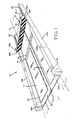
- a vehicle security barrier incorporating various features of the present invention is illustrated at 10 in the figures.
- the security barrier 10 is designed to be easily transported, in either an assembled or disassembled state, to a roadway 11 to provide a means for controlling vehicular travel on the roadway and/or for limiting access to a selected area via such roadway.
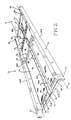
- the security barrier 10 generally comprises a base portion 12 defining a travelway 14 bounded on either side by longitudinal side barriers 16A and 16B.
- a security gate 18 is pivotally mounted on the base portion 12 for selectively closing the travelway 14 to vehicular travel. Accordingly, it will be understood that the barrier 10 is utilized by placing it on the roadway 11 where vehicular travel is to be controlled such that the travelway 14 intercepts the vehicular traffic on the roadway. The gate 18 is then selectively raised to restrict a vehicle's travel from the travelway 14 back onto the roadway.
- the base portion 12 defines a forwardly disposed entryway 20 whereby a vehicle accesses the travelway 14, and a rearwardly disposed exit 22 whereby a vehicle exits the travelway 14.
- entry onto the travelway 14 is facilitated by the entry ramp members 24A and B which are mounted on the forward edge 26 of the base 12, and exit from the travelway 14 is facilitated by the exit ramp members 28A and 28B which are attached to the rearward edge 30 of the base 12.
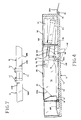
- the entry ramp members 24A and B and the exit ramp members 28A and B can be integral with, or fixedly attached to, the base 12, in the preferred embodiment, the ramp members 24 and 28 are pivotally and releasably attached to the base 12 with hinge members 32 (as illustrated in Figure 4 with respect to the ramp members 28A) such that they more readily engage the surface of the roadway and such that they can be removed during transport.
- the base 12 comprises longitudinal side barriers 16A and 16B.
- the side barriers 16A and B serve primarily to prohibit a vehicle which has entered onto the travelway 14 from exiting other than via the exit 22 or by backing out of the entryway 20.
- the side barriers 16A and B each define a cylinder housing 34 and a gate housing 36 both of which will be discussed further hereinafter.
- the side barriers 16A and B can be provided with detachable curb guides 35, if desired, to facilitate a vehicle's entry onto the travelway 14.
- the base 12 comprises first and second oppositely disposed sections 38A and 38B, respectively, preferably fabricated of a strong durable metal.
- the sections 38A and B define inner edge portions 40A and B, respectively, which are releasably joined by suitable fastening means.
- the inner edge portions 40A and 40B form an overlapping longitudinal joint 42 releasably secured with a plurality of bolts 44.
- the base portion 12 can be fabricated as an intregral unit. However, the ability to break the base portion 12 down into the sections 38A and 38B facilitates transport of the base portion 12.
- each of the sections 38A and B define an opening 46 which is releasably receptive of a travelway panel 48 preferably fabricated of expanded metal.
- a travelway panel 48 preferably fabricated of expanded metal.
- the security gate 18 is pivotally mounted on the base 12 proximate the rearward portion of the base 12 and is disposed such that when raised, the gate 18 blocks the travelway 14 and prohibits a vehicle from exiting the security barrier 10 through the exit 22.
- the gate 18 is fabricated of a strong durable metal.
- the positioning of the gate 18 proximate of the rearward portion of the base 12 allows a vehicle, such as the illustrated vehicle 50, to be driven onto the travelway 14, such that all or substantially all of the vehicle is positioned on the security barrier. It will be appreciated by those skilled in the art that when the vehicle 50 is committed to a position on the security barrier 10 between the side barriers 16A and B, the operators of the security barrier 10 are in a better position to exercise control over the vehicle and its occupants.
- the security gate 18 is pivotally secured to the base 12 with a hinge 52 such that the gate 18 pivots forward to lay flat against the travelway 14 to selectively allow vehicles to pass through the security barrier 10.
- the hinge 52 comprises a plurality of gate mounting segments 54 secured to the gate 18 and a plurality of base segments 56 secured to the base 12, the segments 54 and 56 being designed to interlock and pivotally receive the mounting shafts 58A and B.
- suitable hinge means can be utilized if desired and the illustrated hinge 52 is simply illustrative of a suitable hinge means.
- a pair of forward gate ramps 60 and a pair of rearward gate ramps 62 are provided in the preferred embodiment. It will be noted, however, that the forward gate ramps 60 can be obviated by bevelling the outboard edge 19 of the gate 18 as illustrated by the broken line at 61 of Figure 4..
- the security barrier 10 is provided with reciprocal actuating means.
- actuating means comprises a pair of pneumatic cylinders 64A and B provided with selectively reciprocating actuator arms 66, the cylinders 64 being powered by a suitable compressed gas source (not shown) and provided with suitable control means (not shown).
- a suitable compressed gas source not shown
- suitable control means not shown
- other reciprocal actuator means can be utilized if desired; as for example, hydraulic cylinders or electromagnetic actuators.
- the cylinders 64A and B are housed within the cylinder housings 34A and B, respectively, and are pivotally secured at their rearward end portions to the base 12.
- the opposite end portions 68A and B of the gate 18 extend into the gate housings 36A and B, respectively, and are provided with actuator arm engaging assemblies 70A and 70B. Resultantly, when the actuator arms 66A and B are substantially fully extended, the gate 18 is in a lowered position, and retraction of the actuator arms 66A and B into the cylinders 64A and B, respectively, raises the gate 18 to prohibit vehicles from exiting the barrier 10 via the exit 22.
- the actuator arm engaging assemblies 70A and B comprise a pair of mounting plates 72 and 74 secured to, and disposed substantially perpendicular to, the gate 18 proximate the opposite end portions 68A and B of the gate 18 so as to be selectively received in the gate housing 36A and B.
- the outboard end portion 76 of the actuator arm 66 is received between and pivotally secured to the mounting plates 72 and 74 at a pivot point 78.
- the pivot point 78 is located such that as the gate 18 is pivoted from the travelway 14 to a raised position, the pivot point 78 is at all times above the level of the pivot point of the hinge 52 such that sufficient leverage is provided for the cylinders 64 to raise the gate 18.
- assemblies 70A and B are each provided with a gate housing cover 80 secured to the mounting plates 72 and 74, the covers 80 serving to cover the upper portion of the gate housing 36 when the gate 18 is in a lowered position.
- Each of the covers 80 comprises a first and second cover panel 82 and 84, respectively, pivotally joined by hinge 86.
- the outboard end portion of the second panel 84 carries a follower 88 which is slidably received in a longitudinally disposed elongated opening 90 in each cylinder housing cover 92.
- the barrier 10 in order to further support the gate 18 when in a raised position such that the gate 18 can sustain a substantial impact from a moving vehicle and still prohibit such vehicle from traversing the security barrier 10, the barrier 10 is provided with a gate support means 94.
- the gate support means 94 comprises a support arm 96 having a first end portion 98 pivotally and slidably secured to the gate 12, and a second end portion 100 pivotally secured to the gate 18 proximate the outboard edge 19 of the gate 18.
- a pair of oppositely disposed support guide members 102 and 104 are provided on the base 12, each of the guide members 102 and 104 defining a groove 106, with a stop member 108 also being provided on the base 12 rearward of the guide members 102 and 104.
- the first end portion 98 of the support arm 96 is provided with oppositely disposed mounting stems 110 and 111 which are slidably and pivotally received in the grooves 106 of the guide members 102 and 104 thereby securing the support arm 96 to the base 12.
- the second end portion 100 of the support arm 96 is, in turn, pivotally secured to a gate support mount 112 carried by the gate 18.
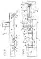
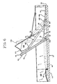
- the gate 18 when the gate 18 is in a lowered position, the first end portion 98 of the support arm 96 is positioned proximate the forward end of the guide members 102 and 104. As the gate 18 is raised the first end portion 98 slides rearwardly and pivots as the second end portion 100 follows the rising motion of the gate. Of course, when the gate 18 rises to the point where the first end portion 98 engages the stop member 108 the support arm 96 braces against the stop member 108 prohibiting further pivoting of the gate 18. In this regard, however, it is contemplated that in normal use, the gate 18 will be raised only to the normally raised position indicated at 114 in Figure 6 such that the gate support means 94 is not engaged.
- the gate 18 will pivot to the full impact position indicated at 116 such that the gate support means 94 will be engaged.
- the gate 18 will pivotally giveway to the point of the full impact position 116 such that damage to the security barrier 10 and the vehicle is avoided or minimized.
- some of the force of the impact is absorbed by the cylinders 64 and in the movement of the gate as the gate 18 pivots from the normally raised position 114 to the full impact position 116.
- the preferred embodiment of the barrier 10 is provided with anti-skid means.
- anti-skid means can comprise cleats or other friction producing devices provided on the lower surface 13 of the base 12, in one preferred embodiment (see Figure 4) such anti-skid means comprises a pair of foot members 118 mounted on the actuator arm engaging assemblies 70A and B of the gate 18 (or directly on the lower edge of the gate 18 if desired) such that the foot members 118 pivot with the gate 18.
- openings 120 are provided in the base 12 to accommodate the pivoting of the foot members 118, and it will be noted that when the gate 18 is raised to the normally raised position 114 the foot members 118 are received in the openings 120, but do not pivot sufficiently to extend below the lower surface 13 of the base 12. However, as the gate 18 is pivoted beyond the normally raised position 114 toward the full impact position, as when a vehicle impacts the gate 18, the foot members 118 pivot below the surface 13 and engage and grip the roadway beneath to prohibit or minimize the skidding of the security barrier 10 on the roadway.
- the anti-skid members 126 can be mounted on the base 12 at selected locations.
- the anti-skid members 126 each comprise a foot member 118 ⁇ which is pivotally mounted on the base 12 proximate an operatively associated opening 127 and downwardly biased with spring biasing means 128. Thus, as illustrated, the foot member 118 ⁇ pivots through the opening 127 and engages the roadway beneath the barrier 10.
- the security gate 18 prohibits the vehicle from exiting through the exit 22 and the side barriers 16A and B prohibit the vehicle from turning to the side and driving around the gate 18.
- the barrier 10 can be provided with anti-back up means to prevent a vehicle from backing out of the entryway 20.
- anti-backup means comprises one or more tire puncture devices 122 pivotally mounted on the base 12 proximate the forward edge 26.
- the puncture devices 122 carry a plurality of teeth 124 which can be pivoted toward the rearward portion of the base 12 such that a vehicle entering the barrier 10 can drive over the puncture devices 122, but when attempting to back over the devices 122 the teeth 124 can be pivoted upwardly such that the tires of the vehicle will be punctured by the teeth 124.
- the present invention provides a vehicle security barrier which can be easily transported to selected locations and placed over a roadway to intercept and control vehicular travel.
- the security barrier 10 is capable of withstanding the impact of a moving vehicle and still prohibit access to the roadway beyond, and offers maximum control over a vehicle and its occupants when the vehicle is stopped on the barrier 10. Therefore, the barrier 10 is ideal for temporary, or permanent road blocks, or for temporarily or permanently controlling vehicular access to a secured area.
- the security barrier 10 can be utilized as a gangway for stairs or as a bridge to provide controlled vehicular travel over a ditch, gully or small stream.
Landscapes
- Engineering & Computer Science (AREA)
- Architecture (AREA)
- Civil Engineering (AREA)
- Structural Engineering (AREA)
- Refuge Islands, Traffic Blockers, Or Guard Fence (AREA)
- Burglar Alarm Systems (AREA)
- Traffic Control Systems (AREA)
Applications Claiming Priority (2)
| Application Number | Priority Date | Filing Date | Title |
|---|---|---|---|
| US07/027,743 US4752152A (en) | 1987-03-19 | 1987-03-19 | Vehicle security barrier |
| US27743 | 1987-03-19 |
Publications (2)
| Publication Number | Publication Date |
|---|---|
| EP0283939A2 true EP0283939A2 (fr) | 1988-09-28 |
| EP0283939A3 EP0283939A3 (fr) | 1990-02-07 |
Family
ID=21839537
Family Applications (1)
| Application Number | Title | Priority Date | Filing Date |
|---|---|---|---|
| EP88104281A Withdrawn EP0283939A3 (fr) | 1987-03-19 | 1988-03-17 | Barrière d'arrêt pour véhicules |
Country Status (3)
| Country | Link |
|---|---|
| US (1) | US4752152A (fr) |
| EP (1) | EP0283939A3 (fr) |
| KR (1) | KR880011418A (fr) |
Cited By (1)
| Publication number | Priority date | Publication date | Assignee | Title |
|---|---|---|---|---|
| EP0468047A4 (en) * | 1990-02-14 | 1992-08-05 | Frommelt Industries, Inc. | Thermal door system |
Families Citing this family (23)
| Publication number | Priority date | Publication date | Assignee | Title |
|---|---|---|---|---|
| US4828424A (en) * | 1987-03-19 | 1989-05-09 | Barrier Concepts, Inc. | Vehicle security barrier |
| US5009542A (en) * | 1990-03-06 | 1991-04-23 | Hardin Jr Paul W | Traffic barrier gate |
| US5211503A (en) * | 1991-04-24 | 1993-05-18 | Energy Absorptions Systems, Inc. | Barrier gate for longitudinal highway barrier |
| US5228237A (en) * | 1992-07-28 | 1993-07-20 | Nasatka Ralph G | Vehicle barrier |
| USD365531S (en) | 1994-01-05 | 1995-12-26 | Stirling Jack L | Security parking barrier for vehicles |
| US5482397A (en) * | 1994-02-18 | 1996-01-09 | Eagle Research Group, Inc. | Tire deflator and method of deflating a tire |
| US5509753A (en) * | 1994-11-22 | 1996-04-23 | Thompson; Clinton C. | Retractable speed bump |
| US6142702A (en) * | 1998-11-25 | 2000-11-07 | Simmons; Jason | Parking space security and status indicator system |
| GB2344128B (en) * | 1998-11-26 | 2002-08-21 | Jaginder Singh Mudhar | Barriers |
| US6382869B1 (en) * | 1999-12-09 | 2002-05-07 | Harry D. Dickinson | Above grade mass displacement trafficway barrier |
| WO2003004776A2 (fr) * | 2001-07-06 | 2003-01-16 | Designated Parking Corp. | Barriere de parking commandee a distance |
| US7101112B2 (en) * | 2004-04-27 | 2006-09-05 | Robert Burns | Security barrier |
| US7775738B2 (en) | 2004-10-22 | 2010-08-17 | Darcy Daniel T | Vehicle barrier system |
| US20070068079A1 (en) * | 2005-07-01 | 2007-03-29 | Mitch Morgan | Vehicle barrier control device |
| US7264417B1 (en) * | 2006-03-23 | 2007-09-04 | Nasatka Barrier, Inc. | Vehicle barrier system, and related method |
| WO2007134396A1 (fr) * | 2006-05-22 | 2007-11-29 | Akras Engineering Pty Ltd | Procédé d'alimentation en carburant et appareil anti-fuite |
| US7794172B2 (en) * | 2006-10-24 | 2010-09-14 | Gregory Robert Winkler | Perimeter anti-ram system |
| US20100003078A1 (en) * | 2008-07-07 | 2010-01-07 | National Taipei University Of Technology | Anti-terror car-attack defending apparatus |
| CA2886919A1 (fr) | 2012-10-01 | 2014-04-10 | The Texas A&M University System | Obstacle escamotable en forme de cale, monte en surface |
| US8678701B1 (en) | 2013-05-28 | 2014-03-25 | Farraj J. A. Aldasem | System for remote control of retractable, ground-based vehicle barriers |
| WO2016069769A1 (fr) | 2014-10-28 | 2016-05-06 | Neusch Innovations, Lp | Barrière cunéiforme active |
| EP3445914B1 (fr) * | 2016-04-20 | 2020-05-20 | Guardiar Europe BVBA | Porte et barrière de sécurité comprenant une porte |
| GB2562059B (en) * | 2017-05-02 | 2020-08-12 | Atg Access Ltd | Improvements in and relating to barriers |
Family Cites Families (25)
| Publication number | Priority date | Publication date | Assignee | Title |
|---|---|---|---|---|
| US2735202A (en) * | 1956-02-21 | Automobile toll collector with barrier | ||
| US1709344A (en) * | 1926-09-02 | 1929-04-16 | Linn W Searles | Railway gate |
| US1765906A (en) * | 1929-10-28 | 1930-06-24 | Harry S Coder | Grade-crossing safety equipment |
| DE649349C (de) * | 1935-10-22 | 1937-08-23 | Eisenwerk Weserhuette Akt Ges | Vorrichtung zum Zerstoeren von auf der Fahrbahn rollenden Radreifen von Fahrzeugen, insbesondere Kampffahrzeugen |
| US2637920A (en) * | 1949-04-28 | 1953-05-12 | Richard H Hallsted | Barrier for motor vehicle parking systems |
| US2935162A (en) * | 1959-05-29 | 1960-05-03 | Roy E Lindsay | Parking barrier |
| US3295255A (en) * | 1964-02-24 | 1967-01-03 | Russo Angelo | Unidirectional traffic control |
| FR1478659A (fr) * | 1966-03-22 | 1967-04-28 | Herse de protection routière | |
| FR2120398A5 (fr) * | 1970-12-31 | 1972-08-18 | Renaux Georges | |
| US3783558A (en) * | 1973-01-17 | 1974-01-08 | Auto Parks Inc | Directional traffic control devices |
| BE845734A (nl) * | 1976-09-01 | 1976-12-31 | Parkeerplaats | |
| FR2417613A1 (fr) * | 1978-02-20 | 1979-09-14 | Gros Pierre | Appareil pour la protection des preposes aux stations services |
| US4152871A (en) * | 1978-03-15 | 1979-05-08 | The United States Of America As Represented By The Attorney General | Vehicle barricade |
| GB2032983A (en) * | 1978-10-25 | 1980-05-14 | Lilleshall Eng Ltd | Vehicle Control Device |
| US4354771A (en) * | 1981-03-06 | 1982-10-19 | Dickinson Harry D | Motorized curb barrier traffic-way controller |
| DE3118487A1 (de) * | 1981-05-09 | 1982-11-25 | Reinhard 7500 Karlsruhe Juraschek | Verbundsystem zum errichten von abgrenzungen und verbundstein fuer dieses system |
| GB8307553D0 (en) * | 1983-03-18 | 1983-04-27 | Oleo Int Holdings Ltd | Movable stops for railway vehicles |
| US4490068A (en) * | 1983-04-25 | 1984-12-25 | Dickinson Harry D | Hydraulic safety barrier traffic-way controller |
| US4574523A (en) * | 1984-03-27 | 1986-03-11 | Nasatka Ralph G | Vehicle barricade or maximum security barrier |
| US4627763A (en) * | 1984-07-03 | 1986-12-09 | Roemac Industrial Sales, Inc. | Vehicle barrier construction |
| US4577991A (en) * | 1984-11-28 | 1986-03-25 | Rolow Willard J | Deployable vehicular barricade |
| US4624600A (en) * | 1985-03-22 | 1986-11-25 | Wagner Richard H | Anti-terrorist vehicle impaler |
| US4630395A (en) * | 1985-07-29 | 1986-12-23 | Nasatka Ralph G | Portable vehicle barricade or portable maximum security barrier |
| ZA87516B (en) * | 1986-07-17 | 1987-09-30 | Alexander Forrest | Vehicle security device |
| FR2606049B1 (fr) * | 1986-11-04 | 1993-03-12 | Mothe Gerard | Barriere anti-intrusion modulaire |
-
1987
- 1987-03-19 US US07/027,743 patent/US4752152A/en not_active Expired - Fee Related
-
1988
- 1988-03-17 EP EP88104281A patent/EP0283939A3/fr not_active Withdrawn
- 1988-03-19 KR KR1019880002935A patent/KR880011418A/ko not_active Withdrawn
Cited By (1)
| Publication number | Priority date | Publication date | Assignee | Title |
|---|---|---|---|---|
| EP0468047A4 (en) * | 1990-02-14 | 1992-08-05 | Frommelt Industries, Inc. | Thermal door system |
Also Published As
| Publication number | Publication date |
|---|---|
| EP0283939A3 (fr) | 1990-02-07 |
| US4752152A (en) | 1988-06-21 |
| KR880011418A (ko) | 1988-10-28 |
| JPS641809A (en) | 1989-01-06 |
Similar Documents
| Publication | Publication Date | Title |
|---|---|---|
| US4752152A (en) | Vehicle security barrier | |
| US4828424A (en) | Vehicle security barrier | |
| EP0125817B1 (fr) | Délimitation déplaçable pour voie de circulation | |
| US5288164A (en) | Combined vehicle barrier | |
| US4576509A (en) | Security gate | |
| US5890832A (en) | Method and apparatus for deflating a tire of a vehicle | |
| CA2268643C (fr) | Herse routiere | |
| US6460292B1 (en) | Barrier gate arm assembly and methods for use thereof | |
| GB2079356A (en) | Retractable road surface ramps | |
| KR0146372B1 (ko) | 도로의 가동성 중앙 분리대 | |
| US5482397A (en) | Tire deflator and method of deflating a tire | |
| CA2081027C (fr) | Plate-forme elevatrice de fauteuil roulant pour vehicules de transport en commun a plancher sureleve | |
| JP2001220916A (ja) | 折畳式支持部を有する動力式車輪止め | |
| EP0092282B1 (fr) | Barrière routière escamotable | |
| GB2032983A (en) | Vehicle Control Device | |
| US20070177940A1 (en) | On-grade barrier and method of its use | |
| US5165839A (en) | Wheelchair lift for railway cars | |
| EP0758698B1 (fr) | Glissière métallique de sécurité pour barrière médiane | |
| JP2001123695A (ja) | 動力式車輪止め装置 | |
| US6394513B2 (en) | Road block, mounted at the rear end of a vehicle | |
| US3295255A (en) | Unidirectional traffic control | |
| KR100871934B1 (ko) | 보도의 차량진입 방지장치 | |
| JP3296908B2 (ja) | 道路防護壁運搬装置 | |
| US20090278014A1 (en) | Overhead track system for roadways | |
| RU2044858C1 (ru) | Способ парковки автомобиля и устройство для его осуществления |
Legal Events
| Date | Code | Title | Description |
|---|---|---|---|
| PUAI | Public reference made under article 153(3) epc to a published international application that has entered the european phase |
Free format text: ORIGINAL CODE: 0009012 |
|
| AK | Designated contracting states |
Kind code of ref document: A2 Designated state(s): AT BE CH DE ES FR GB GR IT LI LU NL SE |
|
| PUAL | Search report despatched |
Free format text: ORIGINAL CODE: 0009013 |
|
| AK | Designated contracting states |
Kind code of ref document: A3 Designated state(s): AT BE CH DE ES FR GB GR IT LI LU NL SE |
|
| STAA | Information on the status of an ep patent application or granted ep patent |
Free format text: STATUS: THE APPLICATION IS DEEMED TO BE WITHDRAWN |
|
| 18D | Application deemed to be withdrawn |
Effective date: 19900808 |