EP0283954A2 - Système d'entraînement d'un compresseur et appareil de conditionnement de l'air l'utilisant - Google Patents
Système d'entraînement d'un compresseur et appareil de conditionnement de l'air l'utilisant Download PDFInfo
- Publication number
- EP0283954A2 EP0283954A2 EP88104356A EP88104356A EP0283954A2 EP 0283954 A2 EP0283954 A2 EP 0283954A2 EP 88104356 A EP88104356 A EP 88104356A EP 88104356 A EP88104356 A EP 88104356A EP 0283954 A2 EP0283954 A2 EP 0283954A2
- Authority
- EP
- European Patent Office
- Prior art keywords
- output
- signal
- motor
- rectifier
- compressor
- Prior art date
- Legal status (The legal status is an assumption and is not a legal conclusion. Google has not performed a legal analysis and makes no representation as to the accuracy of the status listed.)
- Granted
Links
Images



Classifications
-
- F—MECHANICAL ENGINEERING; LIGHTING; HEATING; WEAPONS; BLASTING
- F25—REFRIGERATION OR COOLING; COMBINED HEATING AND REFRIGERATION SYSTEMS; HEAT PUMP SYSTEMS; MANUFACTURE OR STORAGE OF ICE; LIQUEFACTION SOLIDIFICATION OF GASES
- F25B—REFRIGERATION MACHINES, PLANTS OR SYSTEMS; COMBINED HEATING AND REFRIGERATION SYSTEMS; HEAT PUMP SYSTEMS
- F25B49/00—Arrangement or mounting of control or safety devices
- F25B49/02—Arrangement or mounting of control or safety devices for compression type machines, plants or systems
- F25B49/025—Motor control arrangements
-
- G—PHYSICS
- G05—CONTROLLING; REGULATING
- G05D—SYSTEMS FOR CONTROLLING OR REGULATING NON-ELECTRIC VARIABLES
- G05D23/00—Control of temperature
- G05D23/19—Control of temperature characterised by the use of electric means
- G05D23/1906—Control of temperature characterised by the use of electric means using an analogue comparing device
-
- G—PHYSICS
- G05—CONTROLLING; REGULATING
- G05D—SYSTEMS FOR CONTROLLING OR REGULATING NON-ELECTRIC VARIABLES
- G05D23/00—Control of temperature
- G05D23/19—Control of temperature characterised by the use of electric means
- G05D23/20—Control of temperature characterised by the use of electric means with sensing elements having variation of electric or magnetic properties with change of temperature
- G05D23/22—Control of temperature characterised by the use of electric means with sensing elements having variation of electric or magnetic properties with change of temperature the sensing element being a thermocouple
-
- F—MECHANICAL ENGINEERING; LIGHTING; HEATING; WEAPONS; BLASTING
- F25—REFRIGERATION OR COOLING; COMBINED HEATING AND REFRIGERATION SYSTEMS; HEAT PUMP SYSTEMS; MANUFACTURE OR STORAGE OF ICE; LIQUEFACTION SOLIDIFICATION OF GASES
- F25B—REFRIGERATION MACHINES, PLANTS OR SYSTEMS; COMBINED HEATING AND REFRIGERATION SYSTEMS; HEAT PUMP SYSTEMS
- F25B2600/00—Control issues
- F25B2600/02—Compressor control
- F25B2600/021—Inverters therefor
-
- Y—GENERAL TAGGING OF NEW TECHNOLOGICAL DEVELOPMENTS; GENERAL TAGGING OF CROSS-SECTIONAL TECHNOLOGIES SPANNING OVER SEVERAL SECTIONS OF THE IPC; TECHNICAL SUBJECTS COVERED BY FORMER USPC CROSS-REFERENCE ART COLLECTIONS [XRACs] AND DIGESTS
- Y02—TECHNOLOGIES OR APPLICATIONS FOR MITIGATION OR ADAPTATION AGAINST CLIMATE CHANGE
- Y02B—CLIMATE CHANGE MITIGATION TECHNOLOGIES RELATED TO BUILDINGS, e.g. HOUSING, HOUSE APPLIANCES OR RELATED END-USER APPLICATIONS
- Y02B30/00—Energy efficient heating, ventilation or air conditioning [HVAC]
- Y02B30/70—Efficient control or regulation technologies, e.g. for control of refrigerant flow, motor or heating
Definitions
- This invention relates to air conditioning systems and heat pump systems and more specifically to an apparatus for operating the compressor.
- An air conditioning system consists of a motor drive connected to a compressor which pressurizes a refrigerant gas for transfer through suitable piping to a refrigeration coil where the pressurized refrigerant gas is depressurized resulting in cooling.
- a heat pump includes the same general components but operates in reverse.
- the depressurized gas is returned to the compressor for repressurization.
- a blower is connected to circulate air about the refrigeration coil so that the cooling effect of the refrigeration coil cools the air from the blower. Ducting is included to direct the air into an area to be cooled.
- the ducting includes a return air flow path to take warm air from this area so that it may be transferred by the blower about the refrigeration coil for cooling and then back to the area to be cooled.
- residential air conditioners include an electric motor connected to the compressor to power the compressor.
- this electric motor is a single phase 230V 60Hz alternating current motor that operates at one or two speeds to drive the compressor.
- a signal from the thermostat initiates the compressor motor to begin the air conditioning operation.
- the thermostat indicates the occurrence of this second cooler temperature by removing the signal from the compressor causing the air conditioner to stop.
- the starting and stopping of the air conditioner compressor not only results in shorter lifetime for the compressor but results in an inefficient use of electric energy by the motor.
- the compressors include oil circulation to reduce friction and wear on internal components.
- a compressor drive system in accordance with the present invention, includes a rectifier to convert externally supplied single phase alternating current into direct current, a temperature sensor for producing a signal indicative of the ambient air temperature of an area to be either cooled or heated and modulation control circuitry connected to receive the temperature signal.
- the modulation control circuit produces multiphase power and speed control signals which are input to a motor drive switching bridge circuit that modulates the rectifier output in accordance with the multiphase power and speed control signals to produce a multiphase power output at a frequency and voltage that vary in accordance with the temperature signal.
- This power output is connected to the motor which drives the compressor at a speed in accordance with the temperature signal.
- the compressor drive system is disclosed with a current limiting circuit within the modulation control circuit.
- the current limiting circuit is connected to the rectifier to detect the current output from the rectifier. This current output is used by the modulation control circuit to regulate the speed control and multiphase power signals.
- a voltage regulation circuit is included in the modulation control circuit. The voltage regulation circuit is connected across the output of the rectifier and regulates the speed control signal in accordance with the voltage output from the rectifier.
- the modulation control circuit also includes a fault detection circuit that inhibits the production of the multiphase power and speed control signals in the presence of certain fault conditions.
- the fault detection circuit includes a latch which is set upon the occurrence of the fault condition resulting in the inhibiting of the output of the multiphase power and speed control signals. This latch can be reset externally.
- an air conditioner in another preferred embodiment, includes a compressor for pressurizing a refrigeration gas and a refrigeration coil connected to the compressor for depressurizing the refrigeration gas to provide cooling.
- the blower is included for circulating the air through the refrigeration coil and into an area to be cooled.
- a temperature sensor is provided in the area to be cooled to sense the ambient air temperature and to provide a signal indicative thereof.
- a rectifier for converting externally supplied single phase alternating current into direct current is provided and is connected to a motor drive switching bridge circuit.
- a control voltage circuit that is connected to receive the temperature signal and connected to receive a signal indicating the rectifier current output is provided to produce a motor speed signal in response thereto.
- a reference voltage circuit is included to receive the motor speed signal and a reference voltage signal from the rectifier means that indicates the output voltage across the rectifier.
- the reference voltage circuit provides a modified motor speed signal in response to the motor speed signal and reference voltage signal.
- An oscillator circuit is provided that receives the motor speed signal from the control voltage circuit and produces a first and second waveform signals in response to the motor speed signal.
- a frequency modulation circuit is included that receives the first waveform from the oscillator and produces a third waveform and multiphase power signals.
- a comparator is connected to receive the second waveform from the oscillator and the third waveform from the frequency modulation circuit and the modified motor speed signal from the reference voltage circuit and produces a speed control waveform signal.
- a modulation circuit is connected to combine the multiphase power signals from the frequency modulation circuit and the speed control waveform from the comparator to produce multiphase modulated power control signals which are input to the motor drive switching bridge together with the output from the rectifier.
- the motor drive switching bridge produces a multiphase power output in accordance with the multiphase modulated power control signals.
- fault detection circuitry is included connected to the rectifier and the motor drive switching bridge for shutting down the multiphase power production upon the occurrence of a fault condition.
- the output of the motor drive switching bridge circuit is connected to the motor such that the motor drive switching bridge circuit provides a multiphase power to the motor to drive a compressor of the air conditioner at a speed in accordance with the speed control waveform signal.
- the present invention is disclosed as an air conditioning system but should be understood to include a air conditioner or heat pump system.
- an object of the invention is to provide a variable speed drive capability for the compressor wherein the speed is determined by the cooling (or heating in the case of a heat pump) requirements.
- the invention includes a conversion of externally provided single phase 230V 60Hz alternating current power to a direct current which is modified to three phase power in a manner to power and control the speed of the compressor drive motor.
- the production of three phase power is traditionally accomplished by an inverter.
- the pseudo square wave and pulse width modulated converters are of interest here.
- the inverter, control circuitry together with a rectifier and a temperature sensing device provide the regulated compressor drive power. The result is that the variable speed motor drives the compressor in a manner to vary the amounts of freon pressurized resulting in more efficient cooling and/or heating as required.
- a constant torque electric motor is used to drive the compressor.
- the power supplied to the constant torque motor varies as to the power frequency and as to the power voltage in order to vary the motor speed. Since torque is proportional to flux and flux is proportional to frequency and voltage, decreasing the frequency and the voltage to the constant torque motor will decrease the motor speed.
- the motor is a constant torque motor within a frequency range of 6 to 60 Hz since the power voltage will be varied as the power frequency is varied within this power frequency range. From 60Hz to 90Hz, the power voltage is constant at 230V resulting in the motor producing a constant horsepower output over this power frequency range.
- the motor speed becomes controllable resulting in the control of the air conditioner compressor and the corresponding cooling capability of the system.
- the variable cooling capacity results in an improved operation of the compressor since the compressor will be running almost all of the time, reducing the start-up oil circulation problems which effect compressor reliability.
- the constant running of the electric motor reduces the motor start-ups resulting in an increased motor energy efficiency.
- the availability of three phase power enables a smaller three phase motor to replace the traditional larger single phase motor for the same total power output.
- FIGURE 1 is a block diagram illustrating the functional components of the air conditioning system invention.
- the controlling input of the system is the area 80 ambient air temperature which is measured by thermostat 10, which in the preferred embodiment includes a thermocouple to measure temperature, and input to voltage control circuit 12 which produces a corresponding control voltage on line 14.
- the magnitude of this control voltage is a direct function of the input temperature to thermostat 10.
- the control voltage on line 14 is input into a voltage controlled oscillator 18 together with the output of a current limit circuit 16 that is connected by lines 40 and 41 to a resistor 51 to measure the current output of the rectifier 38.
- the output of the voltage control circuit 12 is also input to a reference and boost voltage circuit 20. Circuit 20 serves three purposes.
- the first being to provide a boost voltage when the motor is first turned on in order that enough initial voltage may be supplied to initiate the signal to start the motor.
- the second function of circuit 20 is to regulate the voltage to the motor in accordance with a voltage input from the rectifier on line 21 which is the rectifier output voltage.
- the circuit 20 provides the reference voltage output to comparator 22 that is used with the output on line 23 of the voltage control oscillator 18 to provide a speed control signal to the pulse width modulator drive circuitry 28.
- the output of the voltage control oscillator 18 is provided on line 19 to the frequency modulation control circuit 24 which is input to a divide by 6 circuit 26 to provide the three phase output reference signals to the pulse width modulated drive circuitry 28.
- the pulse width modulated drive circuitry 28 combines the signals from the divide by 6 circuitry 26 and the comparator 22 to produce the signals on line 46 for controlling the motor drive switching bridge 50 which provides three phase power to a motor.
- the output on line 46 is input through an interface circuit 60 to provide the appropriate voltage levels on line 62 to switch the bridge circuit 50.
- the signals output from the pulse width modulated drive circuit 28 control the power output from the motor drive switching bridge circuit 50 and regulate the speed of motor 54.
- the system further includes an overvoltage/undervoltage shutdown circuit 34 connected to measure the voltage output of the rectifier 38, an overcurrent shutdown circuit 36 connected to measure current to the motor 54 on lines 64, 66 and 68, ground fault detection across the rectifier 38 via circuit 31 all which are input to a clamp 42 that sets reset latch 32 when a fault occurs.
- the reset latch 32 also includes an external reset signal 30 that can be used to reset the latch to restart the system after a shutdown.
- the overvoltage/undervoltage shutdown circuit 34 receives a signal indicating the rectifier voltage output as an input on line 21 from the rectifier 38. Upon detecting an undervoltage or an overvoltage condition, the circuit 34 will provide an output to reset latch 32 causing the latch to set and in turn providing a signal to the pulse width modulated drive circuitry 28 which inhibits any output on line 46 resulting in motor 54 being shutdown.
- the overcurrent shutdown circuitry 36 measures the current output from the bridge circuit 50 on lines 64, 66 and 68 and provides an output to the reset latch 32 through clamp 42 when an overcurrent condition is detected causing the latch 32 to be set providing an output to the pulse width modulated drive circuitry 28 inhibiting its output on line 26 resulting in motor 54 being shutdown.
- Ground fault detection circuit 31 is connected by a coil across the output of rectifier 38 to detect a ground fault condition.
- the output of circuit 31 is provided to clamp 42 to set the reset latch 32 upon the occurrence of a ground fault condition.
- the output of latch 32 will then inhibit the output of the pulse width modulated drive circuitry 28 to shutdown motor 54.
- Rectifier 38 is connected to receive single phase alternating current input through an input electromagnetic interference filter 37.
- the input power is 230V single phase 60Hz power.
- the output of rectifier 38 is connected to the motor drive switching bridge circuit 50 across a filter capacitor 47, the ground fault detection circuit 31 coil and the current limiting measurement resistor 51.
- the output of the motor drive switching bridge circuit on lines 64, 66 and 68 are the three phase power lines for the motor 54.
- the motor drive switching bridge circuit 50 then modulates the output of the rectifier 38 in accordance with the signals from the pulse width modulated drive 28 to provide this three phase power.
- Motor 54 is connected to drive compressor 56.
- Compressor 56 circulates a refrigerant gas through piping schematically illustrated as line 72 to a coil 74 to provide cooling.
- the refrigeration coil 74 is connected to ducting 78 and a blower 76.
- the blower 76 circulates air through the ducting 78 and coil 74 into an area 80 to be cooled.
- the thermostat 10 provides a signal to control voltage circuitry 12 indicating the temperature of the area 80 to be cooled which in turn controls the speed of motor 54 to control compressor 56 to control the amount of refrigerant circulated through coil 74 for regulating the cooling of the area 80.
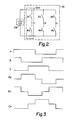
- FIGURE 2 symbolically illustrates the rectifier 38 and motor drive switching BRIDGE CIRCUIT 50.
- Rectifier 38 produces a DC voltage that is input to the motor drive switching BRIDGE CIRCUIT which is represented as three parallel dual serial switches as shown to produce power on three nodes marked A, B and C representing the three phase power input to the motor 54 of FIGURE 1.
- One section including switches S1 and S2 for node A is denoted as block 200.
- the voltage output on node A is represented by curve A of FIGURE 3 representing the phase A output.
- the voltage output on node B and node C are represented as curves B and C.
- FIGURE 4 illustrates the schematic of a circuit having three inputs, AUP-, ADOWN and ADOWN-. These three input signals are input to control transistors Q100, Q102, Q103, Q104 and Q105 to control the switching power transistors Q106 and Q107 which are symbolically shown as switches S1 and S2 in FIGURE 2.
- the switching transistors Q106 and Q107 provide the voltage shown.
- Control transistor Q102 is provided to insure that switching transistor Q106 achieves saturation quickly.
- Q104 is provided to insure that switching transistor Q107 achieves saturation quickly.
- Switching transistors Q103 and Q105 are provided to quickly drain the base current of Q106 and Q107 respectively to insure that the transistors quickly turnoff.
- the output is input to the overcurrent shutdown circuit 36. It should be understood that the output across V+ and V- is one phase of three phases that are input to the motor 54 of FIGURE 1.
- the motor 54 is a constant torque motor, variations in the AC frequency output to the motor across the three phases will result in variations in speed. It is an object of the motor speed control circuitry to provide control of the motor in response to the thermostat voltage input to vary the motor speed and thus vary the cooling capability of the compressor to conform with the environmental conditions in accordance with the thermostat setting.
- FIGURE 5 illustrates a schematic diagram of the motor speed control II of FIGURE 1.
- the following description of the motor speed control incorporates by reference the disclosure of U.S. Patent No. 3,919,610.
- the schematic diagram of FIGURE 5 is divided into sections that correspond to the blocks of FIGURE 1. Specifically, the input from the thermostat 10 occurs on lines 254 and 256 of the voltage control 12 and are input into an operational amplifier 100 to provide the DC voltage reference input to the voltage controlled oscillator 18.
- this reference voltage is input to the reference and boost voltage circuit 20 through an operational amplifier 102 that provides the boost voltage signal from variable resistor R9 adjusted to provide the initial boost voltage to the motor for start-up and the reference voltage signal that is combined with a voltage regulation signal on line 250 from the rectifier circuit to provide the output through operational amplifier 106 which is then input to the comparator 22.
- the voltage controlled oscillator circuit 18 receives the input through operational amplifier 104 and provides an output on node H that is a triangular waveform.
- the output of operational amplifier 116 on node J is a square wave.
- the frequency of the triangular waveform and square wave are the same but together vary in frequency in accordance with the input control voltage signal.
- the square wave is provided to the latch 122 and latch 124 through NOR gate 126 to provide an input to operational amplifier 108 with the triangular waveform of node H.
- the output of operational amplifier 108 on node K resembles the voltage waveform labeled VREF in FIGURE 6. This waveform is then compared in comparator 110 with the reference voltage output of the reference and boost voltage circuit 20 to result in a waveform at node M.
- FIGURE 7 illustrates three waveforms at node M for three different reference voltages X, Y and Z illustrated in FIGURE 6.
- the waveform in FIGURE 6 is produced over a 60 degree interval that will be superimposed on the three phase power output to the motor to regulate the motor speed.
- the output of the voltage oscillator section 18 and specifically the square wave output of node J and through latch 122 is input to a counter 128 (which in the preferred embodiment is a CD 4018) for frequency modulation control to produce a signal that will be divided by 6 in the divide by 6 circuitry 26 and counter 142 to produce a three phase output voltage reference signal.
- a counter 128 which in the preferred embodiment is a CD 4018 for frequency modulation control to produce a signal that will be divided by 6 in the divide by 6 circuitry 26 and counter 142 to produce a three phase output voltage reference signal.
- FIGURE 8 illustrates the three phase output signals A. B and C which without any speed control signaling would be the outputs of the motor drive switching bridge circuit 50 of FIGURE 1.
- the waveform of A, B and C in FIGURE 8 are divided up into 60 degree wide zones labeled 1, 2 and 3 with the top line of the figure defining the different zone areas.
- zone areas for the phase waveforms A, B and C and for the phase to phase waveform combinations AB, BC and CA denote where the speed control voltage waveforms within their respective zones such as those in FIGURE 7 would be placed.
- FIGURE 9 illustrates the voltage speed control waveform output VM imposed in the respective zones for phase waveforms A, B and C and the phase to phase waveforms AB, BC and CA.
- the phase waveforms A, B and C would be output from the pulse width modulated drive circuit 28 in NAND gates 172, 174, 176 and the OR gates 194, 196 and 198 to provide the outputs to drive the motor drive switching bridge circuit.
- the speed control circuit of FIGURE 5 further includes the overcurrent shutdown circuit 36 that is connected to the reset latch 32 containing the latched NOR gates 168 and 170.
- the inputs to the overcurrent shutdown circuits 264, 266 and 268 are connected to the motor drive switching bridge circuit at line 300 of FIGURE 4 for the A, B and C phases.
- latch 32 receives an input which shuts down the output of the pulse width modulated drive circuit 28 through the NOR gates 202, 216 and 220 and NAND gates 192, 212 and 214.
- the input to the current limit circuitry on lines 258 and 260 from the rectifier circuit are used to determine the presence of an excessive current and which results in an input to reset latch 32 again causing a shutoff of the pulse width modulated drive circuit 28 output at NOR gates 202 and 220 and NAND gates 192 and 212.
- the overvoltage/undervoltage shutdown circuit 34 is connected to the rectifier circuit 38 by line 272 to detect an overvoltage or undervoltage output from the rectifier.
- the overvoltage/undervoltage shutdown circuit 34 is configured to have a hysterisis or overvoltage and undervoltage operating range to permit small variations in the rectifier voltage output without shutting down the system.
- the output of the overvoltage/undervoltage circuit 34 is input to the reset latch 32 which again will shutdown the output of the pulse width modulated drive circuit 28 when an overvoltage or undervoltage condition is detected.
- the reset latch 32 also receives an input on line 252 which is a ground fault detection line that is connected to the rectifier circuit. This ground fault detection line will indicate the presence of a ground fault between the rectifier circuit 38 and the motor drive switching bridge circuit 50.
- Line 262 provides the external reset to the latch 32 to reset the latch after the latch has detected a fault condition causing a shutdown of the output of the pulse width modulated drive.
Landscapes
- Engineering & Computer Science (AREA)
- Physics & Mathematics (AREA)
- General Physics & Mathematics (AREA)
- Automation & Control Theory (AREA)
- Mechanical Engineering (AREA)
- Thermal Sciences (AREA)
- General Engineering & Computer Science (AREA)
- Control Of Ac Motors In General (AREA)
- Control Of Positive-Displacement Pumps (AREA)
- Air Conditioning Control Device (AREA)
Applications Claiming Priority (2)
| Application Number | Priority Date | Filing Date | Title |
|---|---|---|---|
| US2830987A | 1987-03-20 | 1987-03-20 | |
| US28309 | 1987-03-20 |
Publications (3)
| Publication Number | Publication Date |
|---|---|
| EP0283954A2 true EP0283954A2 (fr) | 1988-09-28 |
| EP0283954A3 EP0283954A3 (en) | 1990-05-16 |
| EP0283954B1 EP0283954B1 (fr) | 1992-09-30 |
Family
ID=21842721
Family Applications (1)
| Application Number | Title | Priority Date | Filing Date |
|---|---|---|---|
| EP88104356A Expired - Lifetime EP0283954B1 (fr) | 1987-03-20 | 1988-03-18 | Système d'entraînement d'un compresseur et appareil de conditionnement de l'air l'utilisant |
Country Status (3)
| Country | Link |
|---|---|
| EP (1) | EP0283954B1 (fr) |
| JP (1) | JPS63279043A (fr) |
| DE (1) | DE3874925T2 (fr) |
Cited By (16)
| Publication number | Priority date | Publication date | Assignee | Title |
|---|---|---|---|---|
| WO1993022716A1 (fr) * | 1992-04-30 | 1993-11-11 | Samsung Electronics Co., Ltd. | Circuit de commande de compresseur |
| EP0837549A3 (fr) * | 1996-10-18 | 1999-07-07 | Hitachi, Ltd. | Dispositif de contrôle d'un moteur à découpage en mode PMW/PAM, entraínement moteur et dispositif de climatisation en faisant usage |
| US7081734B1 (en) | 2005-09-02 | 2006-07-25 | York International Corporation | Ride-through method and system for HVACandR chillers |
| US7208891B2 (en) | 2005-05-06 | 2007-04-24 | York International Corp. | Variable speed drive for a chiller system |
| US7332885B2 (en) | 2005-09-02 | 2008-02-19 | Johnson Controls Technology Company | Ride-through method and system for HVAC&R chillers |
| US7746020B2 (en) | 2007-01-22 | 2010-06-29 | Johnson Controls Technology Company | Common mode & differential mode filter for variable speed drive |
| EP1286122A3 (fr) * | 2001-08-21 | 2010-11-24 | Liebherr-Hausgeräte Gmbh | Appareil de réfrigération et de congélation |
| US7957166B2 (en) | 2007-10-30 | 2011-06-07 | Johnson Controls Technology Company | Variable speed drive |
| US8004803B2 (en) | 2007-05-08 | 2011-08-23 | Johnson Controls Technology Company | Variable speed drive |
| US8149579B2 (en) | 2008-03-28 | 2012-04-03 | Johnson Controls Technology Company | Cooling member |
| US8174853B2 (en) | 2007-10-30 | 2012-05-08 | Johnson Controls Technology Company | Variable speed drive |
| US8193756B2 (en) | 2008-10-03 | 2012-06-05 | Johnson Controls Technology Company | Variable speed drive for permanent magnet motor |
| US8495890B2 (en) | 2007-01-22 | 2013-07-30 | Johnson Controls Technology Company | Cooling member |
| CN103291592A (zh) * | 2013-06-04 | 2013-09-11 | 宁波奥克斯电气有限公司 | 变频多联机压缩机输出能力的控制方法 |
| CN110145460A (zh) * | 2019-06-03 | 2019-08-20 | 国家电网有限公司 | 一种双水泵轮换启停控制回路 |
| US20210101448A1 (en) * | 2019-10-03 | 2021-04-08 | Toyota Jidosha Kabushiki Kaisha | Vehicle-mounted temperature controller |
Families Citing this family (3)
| Publication number | Priority date | Publication date | Assignee | Title |
|---|---|---|---|---|
| JP2804521B2 (ja) * | 1989-06-30 | 1998-09-30 | シャープ株式会社 | 可変能力型空気調和装置 |
| CN104315651B (zh) * | 2014-09-30 | 2017-02-15 | 海信科龙电器股份有限公司 | 一种单相变频空调控制方法及控制器 |
| CN107065974A (zh) * | 2017-06-19 | 2017-08-18 | 无锡新辉龙科技有限公司 | 一种用于半导体管道加热器的温度控制器 |
Family Cites Families (2)
| Publication number | Priority date | Publication date | Assignee | Title |
|---|---|---|---|---|
| JPH0683590B2 (ja) * | 1984-07-04 | 1994-10-19 | 株式会社東芝 | 空気調和機 |
| JPS62178832A (ja) * | 1986-02-03 | 1987-08-05 | Hitachi Ltd | インバ−タ付空気調和機の制御回路 |
-
1988
- 1988-03-18 DE DE8888104356T patent/DE3874925T2/de not_active Expired - Fee Related
- 1988-03-18 EP EP88104356A patent/EP0283954B1/fr not_active Expired - Lifetime
- 1988-03-22 JP JP63068026A patent/JPS63279043A/ja active Pending
Cited By (25)
| Publication number | Priority date | Publication date | Assignee | Title |
|---|---|---|---|---|
| WO1993022716A1 (fr) * | 1992-04-30 | 1993-11-11 | Samsung Electronics Co., Ltd. | Circuit de commande de compresseur |
| EP0837549A3 (fr) * | 1996-10-18 | 1999-07-07 | Hitachi, Ltd. | Dispositif de contrôle d'un moteur à découpage en mode PMW/PAM, entraínement moteur et dispositif de climatisation en faisant usage |
| US6075328A (en) * | 1996-10-18 | 2000-06-13 | Hitachi, Ltd. | PWM/PAM control mode switching type motor control apparatus, and motor drive and air-conditioner using the same |
| EP1286122A3 (fr) * | 2001-08-21 | 2010-11-24 | Liebherr-Hausgeräte Gmbh | Appareil de réfrigération et de congélation |
| US7208891B2 (en) | 2005-05-06 | 2007-04-24 | York International Corp. | Variable speed drive for a chiller system |
| US7081734B1 (en) | 2005-09-02 | 2006-07-25 | York International Corporation | Ride-through method and system for HVACandR chillers |
| US7332885B2 (en) | 2005-09-02 | 2008-02-19 | Johnson Controls Technology Company | Ride-through method and system for HVAC&R chillers |
| US8014110B2 (en) | 2007-01-22 | 2011-09-06 | Johnson Controls Technology Company | Variable speed drive with integral bypass contactor |
| US8495890B2 (en) | 2007-01-22 | 2013-07-30 | Johnson Controls Technology Company | Cooling member |
| US7876561B2 (en) | 2007-01-22 | 2011-01-25 | Johnson Controls Technology Company | Cooling systems for variable speed drives and inductors |
| US7764041B2 (en) | 2007-01-22 | 2010-07-27 | Johnson Controls Technology Company | System and method to extend synchronous operation of an active converter in a variable speed drive |
| US7746020B2 (en) | 2007-01-22 | 2010-06-29 | Johnson Controls Technology Company | Common mode & differential mode filter for variable speed drive |
| US8004803B2 (en) | 2007-05-08 | 2011-08-23 | Johnson Controls Technology Company | Variable speed drive |
| US8174853B2 (en) | 2007-10-30 | 2012-05-08 | Johnson Controls Technology Company | Variable speed drive |
| US7957166B2 (en) | 2007-10-30 | 2011-06-07 | Johnson Controls Technology Company | Variable speed drive |
| US8149579B2 (en) | 2008-03-28 | 2012-04-03 | Johnson Controls Technology Company | Cooling member |
| US8336323B2 (en) | 2008-10-03 | 2012-12-25 | Johnson Controls Technology Company | Variable speed drive with pulse-width modulated speed control |
| US8286439B2 (en) | 2008-10-03 | 2012-10-16 | Johnson Control Technology Company | Variable speed drive for permanent magnet motor |
| US8258664B2 (en) | 2008-10-03 | 2012-09-04 | Johnson Controls Technology Company | Permanent magnet synchronous motor and drive system |
| US8353174B1 (en) | 2008-10-03 | 2013-01-15 | Johnson Controls Technology Company | Control method for vapor compression system |
| US8193756B2 (en) | 2008-10-03 | 2012-06-05 | Johnson Controls Technology Company | Variable speed drive for permanent magnet motor |
| CN103291592A (zh) * | 2013-06-04 | 2013-09-11 | 宁波奥克斯电气有限公司 | 变频多联机压缩机输出能力的控制方法 |
| CN110145460A (zh) * | 2019-06-03 | 2019-08-20 | 国家电网有限公司 | 一种双水泵轮换启停控制回路 |
| US20210101448A1 (en) * | 2019-10-03 | 2021-04-08 | Toyota Jidosha Kabushiki Kaisha | Vehicle-mounted temperature controller |
| US11951806B2 (en) * | 2019-10-03 | 2024-04-09 | Toyota Jidosha Kabushiki Kaisha | Vehicle-mounted temperature controller |
Also Published As
| Publication number | Publication date |
|---|---|
| EP0283954B1 (fr) | 1992-09-30 |
| JPS63279043A (ja) | 1988-11-16 |
| EP0283954A3 (en) | 1990-05-16 |
| DE3874925D1 (de) | 1992-11-05 |
| DE3874925T2 (de) | 1993-04-01 |
Similar Documents
| Publication | Publication Date | Title |
|---|---|---|
| US4893479A (en) | Compressor drive system | |
| US5123080A (en) | Compressor drive system | |
| EP0283954B1 (fr) | Système d'entraînement d'un compresseur et appareil de conditionnement de l'air l'utilisant | |
| US5436547A (en) | Inverter and air conditioner controlled by normal and defrost energization patterns | |
| KR930010466B1 (ko) | 냉난방겸용 공조기의 콤프레셔 기동 제어방법 | |
| KR890004935B1 (ko) | 인버터 부착 공기조화기의 제어회로 | |
| EP0156078B1 (fr) | Système de contrôle de température pour moteur à combustion interne | |
| KR920009180B1 (ko) | 공기조화기의 전류 제어회로 및 그 방법 | |
| US6710573B2 (en) | Method of controlling pulsed AC power | |
| EP1111766A1 (fr) | Organe de commande de moteur de modulation d'impulsions en duree/en amplitude (pwm/pam), conditionneur d'air, et procede de commande de moteur | |
| CN112640283A (zh) | 逆变器的控制方法、针对交流负载的电力供给系统、制冷回路 | |
| KR970069851A (ko) | 높은 구동 효율로 엘리베이터 교류 전동기를 제어하는 제어장치 | |
| JPH0450496B2 (fr) | ||
| US4201061A (en) | Automatic chilled water setpoint temperature control | |
| JP2804796B2 (ja) | 電動機制御装置 | |
| JPH1169861A (ja) | 電動機制御装置、この電動機制御装置を用いた冷凍サイクル装置及び空気調和機 | |
| KR960001663A (ko) | 공기조화기의 운전제어장치 및 그 방법 | |
| KR960001662A (ko) | 공기조화기의 제어장치 및 그 방법 | |
| JP2007028781A (ja) | 空気調和機の直流電源装置 | |
| KR20070030073A (ko) | 인버터 에어컨의 구동장치 및 그 제어방법 | |
| KR100208341B1 (ko) | 냉장고용 팬모터의 속도제어방법 및 속도제어장치 | |
| JPH042859B2 (fr) | ||
| US20260081552A1 (en) | Motor driver for setting duty cycles based on temperature | |
| JPH06319264A (ja) | インバータ制御装置 | |
| JPH02142387A (ja) | 無整流子電動機の駆動回路 |
Legal Events
| Date | Code | Title | Description |
|---|---|---|---|
| PUAI | Public reference made under article 153(3) epc to a published international application that has entered the european phase |
Free format text: ORIGINAL CODE: 0009012 |
|
| AK | Designated contracting states |
Kind code of ref document: A2 Designated state(s): DE FR GB IT |
|
| PUAL | Search report despatched |
Free format text: ORIGINAL CODE: 0009013 |
|
| AK | Designated contracting states |
Kind code of ref document: A3 Designated state(s): DE FR GB IT |
|
| 17P | Request for examination filed |
Effective date: 19900911 |
|
| 17Q | First examination report despatched |
Effective date: 19901219 |
|
| RAP1 | Party data changed (applicant data changed or rights of an application transferred) |
Owner name: RANCO INCORPORATED OF DELAWARE |
|
| GRAA | (expected) grant |
Free format text: ORIGINAL CODE: 0009210 |
|
| ITF | It: translation for a ep patent filed | ||
| AK | Designated contracting states |
Kind code of ref document: B1 Designated state(s): DE FR GB IT |
|
| ET | Fr: translation filed | ||
| REF | Corresponds to: |
Ref document number: 3874925 Country of ref document: DE Date of ref document: 19921105 |
|
| PGFP | Annual fee paid to national office [announced via postgrant information from national office to epo] |
Ref country code: FR Payment date: 19930310 Year of fee payment: 6 |
|
| PGFP | Annual fee paid to national office [announced via postgrant information from national office to epo] |
Ref country code: GB Payment date: 19930316 Year of fee payment: 6 |
|
| PGFP | Annual fee paid to national office [announced via postgrant information from national office to epo] |
Ref country code: DE Payment date: 19930322 Year of fee payment: 6 |
|
| PLBE | No opposition filed within time limit |
Free format text: ORIGINAL CODE: 0009261 |
|
| STAA | Information on the status of an ep patent application or granted ep patent |
Free format text: STATUS: NO OPPOSITION FILED WITHIN TIME LIMIT |
|
| 26N | No opposition filed | ||
| PG25 | Lapsed in a contracting state [announced via postgrant information from national office to epo] |
Ref country code: GB Effective date: 19940318 |
|
| GBPC | Gb: european patent ceased through non-payment of renewal fee |
Effective date: 19940318 |
|
| PG25 | Lapsed in a contracting state [announced via postgrant information from national office to epo] |
Ref country code: FR Effective date: 19941130 |
|
| PG25 | Lapsed in a contracting state [announced via postgrant information from national office to epo] |
Ref country code: DE Effective date: 19941201 |
|
| REG | Reference to a national code |
Ref country code: FR Ref legal event code: ST |
|
| PG25 | Lapsed in a contracting state [announced via postgrant information from national office to epo] |
Ref country code: IT Free format text: LAPSE BECAUSE OF NON-PAYMENT OF DUE FEES;WARNING: LAPSES OF ITALIAN PATENTS WITH EFFECTIVE DATE BEFORE 2007 MAY HAVE OCCURRED AT ANY TIME BEFORE 2007. THE CORRECT EFFECTIVE DATE MAY BE DIFFERENT FROM THE ONE RECORDED. Effective date: 20050318 |