EP0283988A2 - Dispositif et procédé pour la fabricat d'un mélange réactif de matiere plastique - Google Patents
Dispositif et procédé pour la fabricat d'un mélange réactif de matiere plastique Download PDFInfo
- Publication number
- EP0283988A2 EP0283988A2 EP88104458A EP88104458A EP0283988A2 EP 0283988 A2 EP0283988 A2 EP 0283988A2 EP 88104458 A EP88104458 A EP 88104458A EP 88104458 A EP88104458 A EP 88104458A EP 0283988 A2 EP0283988 A2 EP 0283988A2
- Authority
- EP
- European Patent Office
- Prior art keywords
- mixing chamber
- valve element
- outlet
- slide
- piston
- Prior art date
- Legal status (The legal status is an assumption and is not a legal conclusion. Google has not performed a legal analysis and makes no representation as to the accuracy of the status listed.)
- Withdrawn
Links
Images


Classifications
-
- B—PERFORMING OPERATIONS; TRANSPORTING
- B29—WORKING OF PLASTICS; WORKING OF SUBSTANCES IN A PLASTIC STATE IN GENERAL
- B29B—PREPARATION OR PRETREATMENT OF THE MATERIAL TO BE SHAPED; MAKING GRANULES OR PREFORMS; RECOVERY OF PLASTICS OR OTHER CONSTITUENTS OF WASTE MATERIAL CONTAINING PLASTICS
- B29B7/00—Mixing; Kneading
- B29B7/74—Mixing; Kneading using other mixers or combinations of mixers, e.g. of dissimilar mixers ; Plant
- B29B7/76—Mixers with stream-impingement mixing head
- B29B7/7631—Parts; Accessories
- B29B7/7636—Construction of the feed orifices, bores, ports
- B29B7/7642—Adjustable feed orifices, e.g. for controlling the rate of feeding
-
- B—PERFORMING OPERATIONS; TRANSPORTING
- B29—WORKING OF PLASTICS; WORKING OF SUBSTANCES IN A PLASTIC STATE IN GENERAL
- B29B—PREPARATION OR PRETREATMENT OF THE MATERIAL TO BE SHAPED; MAKING GRANULES OR PREFORMS; RECOVERY OF PLASTICS OR OTHER CONSTITUENTS OF WASTE MATERIAL CONTAINING PLASTICS
- B29B7/00—Mixing; Kneading
- B29B7/74—Mixing; Kneading using other mixers or combinations of mixers, e.g. of dissimilar mixers ; Plant
- B29B7/76—Mixers with stream-impingement mixing head
- B29B7/7631—Parts; Accessories
- B29B7/7652—Construction of the discharge orifice, opening or nozzle
- B29B7/7657—Adjustable discharge orifices, openings or nozzle openings, e.g. for controlling the rate of dispensing
-
- B—PERFORMING OPERATIONS; TRANSPORTING
- B29—WORKING OF PLASTICS; WORKING OF SUBSTANCES IN A PLASTIC STATE IN GENERAL
- B29B—PREPARATION OR PRETREATMENT OF THE MATERIAL TO BE SHAPED; MAKING GRANULES OR PREFORMS; RECOVERY OF PLASTICS OR OTHER CONSTITUENTS OF WASTE MATERIAL CONTAINING PLASTICS
- B29B7/00—Mixing; Kneading
- B29B7/74—Mixing; Kneading using other mixers or combinations of mixers, e.g. of dissimilar mixers ; Plant
- B29B7/76—Mixers with stream-impingement mixing head
- B29B7/7663—Mixers with stream-impingement mixing head the mixing head having an outlet tube with a reciprocating plunger, e.g. with the jets impinging in the tube
Definitions
- the invention relates to a device for forming a plastic reaction mixture from at least two components, in particular for the production of polyurethane foam products, and to methods therefor.
- a known device (DE-PS 22 19 389) has, in one of several versions, two rotary valves accommodated in housing bores, the hollow interior of which is connected to supply lines for the components in each rotational position by slots in the housing.
- Each rotary valve has a radial injection opening and a radial return bore.
- injection openings point through cutouts in a wall into an obelisk-like widening mixing chamber, while the return bores are closed by the housing bores surrounding the rotary slide valves, or the injection openings are closed by the housing bores, while the return bores are connected to the Return lines leading housing channels match.
- the rotary valves are fitted with intermeshing gears.
- a molding tool is placed on the outwardly widening mixing chamber in such a way that the mixing chamber is located at the location of a sprue which leads to a mold cavity.
- the rotary valve should be easily rotatable in the housing bores and yet be fitted in a sealing manner. These are contradictory claims. If there is play between a rotary slide valve and the wall of the housing bore or if this occurs due to wear, then a secure closing of the radial openings is not guaranteed. In addition, after each working cycle, the mixture that has reacted remains in the mixing chamber, which then has to be removed from it. In order to prevent the mixture residues that have reacted in the mixing chamber from adhering to their walls and to the transitions to the lateral surfaces of the rotary valves, a special tear-off device must be provided for the rotary valves.
- the object of the invention is to provide a device of the type mentioned, which meets the varied requirements with regard to training and functionality to a high degree. This applies, among other things, to the fulfillment of the prerequisites for a safe and inexpensive sequence of the processes which ultimately also determine the product to be produced in one work cycle, in particular with regard to the control of the component supply or return and the transition between these two states.
- the passage cross-sections for the components for entry into the mixing chamber can be adjusted and adjusted according to the requirements.
- the invention also pays particular attention to avoiding, as far as possible, impairment of the product to be produced by any imperfections at the start of the mixing process.
- the invention also aims at the advantageous design of mixing devices in detail and is also aimed at procedures for the formation of reaction mixtures using inexpensive devices. Further problems connected with all of this, with which the invention is concerned, result from the respective explanation of the indicated solution.
- the invention provides that the valve element has an end bearing surface which rests against a seat surface of the housing, that from the seat surface on the one hand a mixing chamber inlet and on the other hand an outlet channel, at least with a part of its cross section , goes out that the outlet opening of the valve element in the end bearing surface of the same is arranged eccentrically to the main axis, in such a way that this outlet opening can be connected to the mixing chamber inlet or to the outlet channel by rotating the valve element in each case, and that an ejection slide is assigned to the mixing chamber which can be moved back and forth by means of a drive between a retracted position and an advanced position which at least largely fills the mixing chamber.
- Such a device is characterized by a number of essential advantages. Because the functionally assigned openings for the passage of the relevant component, be it in the injection process, be it in the return or circulation, in flat contact surfaces, namely an end face of the valve element and a seat surface of the housing, a perfect and secure seal is achieved in the functionally assigned parts without impairing the mobility of the valve element.
- the valve elements can, if necessary, be additionally loaded by one or more compression springs or other suitable pressure application elements in the sense of pressing the bearing surface onto the seat surface.
- the discharge slide assigned to the mixing chamber means that ensures that the mixing chamber remains free of residues.
- the mixing chamber expediently has a regular cross section, in particular a circular cross section, although other shapes are also not excluded.
- the measure of providing an ejection slide in a cylindrical mixing chamber is known per se, but has not yet been applied to a device of the type in question here.
- valve elements also offers the possibility of a largely revealing design in detail.
- the outlet opening which can advantageously be a nozzle, be it a perforated nozzle or, in particular, an adjustable nozzle.
- it can be an or the like with an adjustable needle. act provided nozzle.
- this interior is at an angle to the main axis of the valve element arranged. This results in a simple design that is also inexpensive to manufacture.
- the design of the device is such that the directions of the outlet openings of the valve elements are at an acute angle in the injection position. This is very convenient for the mixing process.
- the angle is advantageously around 60 degrees, but can also be smaller.
- Rack and pinion drives can be provided for rotating the valve elements, as is known in principle. However, other suitable drive elements can also be considered.
- a pressure medium drive for rotating at least one valve element is combined with a pressure medium drive for moving the ejection slide. This not only has the advantage of a compact design, but can also be advantageous for the function.
- the training can be made so that subsequent to a first cylinder with the first piston a second cylinder with a second piston as the valve element drive is provided as the drive for the ejection slide, a piston rod of the second piston being coupled to a transmission member leading to the valve element via a motion-transmitting connection.
- two mutually corresponding spaces of the two cylinders are connected to one another in terms of lines. Pressure medium can then be fed to both cylinders from one line, so that both pistons are acted upon accordingly.
- the second piston can have a plunger facing the first piston and arranged for temporary abutment against it. This means that the second piston is mechanically entrained by the first piston when it falls and brought into the end position. This not only represents a simple design with regard to the control of the processes, but also has the advantage that the strokes of the pistons can be selected cheaply.
- the stroke of the second piston for the valve element drive is advantageously only a fraction of the stroke of the first piston for the ejection slide drive.
- an expediently adjustable free travel can be provided, such that the gear element and thus the valve element only undergoes an adjustment when the ejection slide has already covered a certain distance.
- a device is particularly well suited, inter alia, for carrying out a method in which, at the end of a mixing process, the valve elements are only adjusted from their injection position in the direction of the circulation position. when the discharge valve has moved so far that it covers the mixing chamber inlets.
- the invention further relates to a device for forming a plastic reaction mixture from at least two components, in particular for the production of polyurethane foam products, with a housing in which an inlet channel and an outlet channel are provided for each component, a mixing chamber with inlets for the components and an outlet for the mixture. It is characterized in that there is an additional chamber arranged at an angle to the mixing chamber in relation to the mixing chamber inlets for the components. This not only contributes to the intensive mixing of the components, but also has the important advantage that the initial mixture, which may not be perfect at first, does not reach the mold cavity first.
- the additional chamber is expediently arranged at right angles to the mixing chamber. Depending on the requirements, this angle can also be chosen differently.
- An auxiliary slide whose cross-section is adapted is advantageously provided in the additional chamber and can be moved back and forth by means of a controllable drive between a rear position and a front end position in which an end face of the auxiliary slide forms part of the wall of the mixing chamber.
- the cross section of the additional chamber and, accordingly, that of the auxiliary slide can be circular. In certain cases, however, it can also be advantageous choose a prismatic cross-section, namely a square or rectangular cross-section.
- the invention further relates to a method for forming a plastic reaction mixture from at least two components with a device which has one or more features of the type explained above.
- the method is characterized in that the auxiliary slide is moved into its rear position in a timed connection with the opening of the mixing chamber inlets, so that the additional chamber is thereby released, in each working cycle with the auxiliary slide located in its front final position and the exhaust slide retracted that towards the end of the mixing process, before the sealing of the mixing chamber inlets and the advancement of the ejection slide, the auxiliary slide is again brought into its front final position, whereupon the ejection slide moves forward.
- the invention is primarily intended for use in so-called high-pressure mixing processes. However, use in lower pressure ranges is not excluded.
- the device shown is used to form a mixture of two components, as is possible for the production of foam parts, in particular those made of polyurethane.
- foam parts in particular those made of polyurethane.
- a cylindrical mixing chamber 2 the outlet 3 of which can be attached directly to the inlet of a mold (not shown), as is known per se.
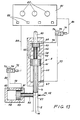
- An ejection slide 4, the cross-section of which corresponds to that of the mixing chamber 2, is by means of a drive designated overall by the number 5 from a retracted position shown in FIG. 1 and thus releasing the mixing chamber 2 into an advanced position, at least largely filling the mixing chamber, in which closes its end face in particular with the end of the outlet 3 of the mixing chamber 2, and vice versa.
- the center axis of the mixing chamber 2 is designated by the letter M.
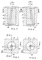
- valve assemblies V1 and V2 are arranged in the housing 1 so that their main axes H are at an acute angle to one another, in particular an angle between 50 and 70 degrees.
- Each valve assembly V1 and V2 has a valve element 11 which can be rotated about the main axis H in a stepped housing bore 12.
- each valve element 11 has an interior 14 in the form of a bore or the like. , whose longitudinal axis L is inclined at an acute angle a with respect to the main axis H, such that an outlet opening 15 of the valve element 11 located at the end of the cavity 14 has an eccentric position with respect to the main axis H.
- Each valve element 11 has an end bearing surface 16 which bears against a seat surface 17 of the housing 1.
- the valve elements 11 are loaded by plate spring assemblies 18 with such a force that the bearing surface 16 is held firmly against the seat surface 17 while leaving a rotating sliding movement. For this purpose, a slight play is left between the shoulder 13 in the bore 12 and a shoulder on the valve element 11 facing it.
- the other end of the plate spring assembly rests on a cover plate 19 fastened to the housing.
- Numbers 21 and 23 denote inlet channels for the two components leading to valve assemblies V1 and V2, and numbers 22 and 24 outlet channels for the components.
- Corresponding pipe or hose lines, which are connected to the housing 1 by means of known connecting parts, are used for supply and discharge.
- the supply devices for the components with containers, metering pumps or the like. can be of a known type and are not shown.
- the inlet channels 21 and 23 open into annular recesses 25 in the housing 1.
- the valve elements 11 have radial bores 26, via which a permanent connection between the interior 14 and the recesses gene 25 and thus the inlet channels 21 and 23 is made.
- each seat 17 there is an inlet 27 leading to the mixing chamber 2, via which the relevant component reaches the mixing chamber 2 during operation. Furthermore, the end of the outlet channel 22 or 24 extends from the seat 17. In the embodiment shown, the outlet channel 22 or 24 continues in the area of the seat 17 as a groove up to a junction 28.
- Both the inlet 27 and the junction 28 are arranged radially offset with respect to the main axis H, in different directions, in the advantageous embodiment shown at an angle of 90 degrees. This can be seen in particular in FIGS. 4 and 6.
- the outlet opening 15 of each valve element 11 is arranged in the bearing surface 16 correspondingly eccentrically to the main axis H, such that this outlet opening 15 by rotating the valve element 11 about the main axis H either with the mixing chamber inlet 27 or with the outlet channel 22 or 24 the confluence point 28 brought to cover, ie can be connected to produce a flow path.
- the position and size of the individual openings or orifices can be selected so that at the transition from one position to the other there is at least one position in which the outlet opening is blocked off by the seat 17.
- the training can also be carried out in such a way that there is possibly a very slight overlap, so that there is a smooth transition.
- valve elements 11 and the parts surrounding them are designed and arranged such that the directions of the outlet openings 15 of the valve elements in the injection position and thus the paths which the rays of the material take through the inlets 27 are at an acute angle.
- This angle is designated by the letter b in FIG. 10. It is advantageously about 60 degrees. In practice, this angle is comparable or essentially the same as the angle formed by the main axes H of the two valve assemblies V1 and V2 (see FIG. 2).
- valve elements 11 or their outlet openings 15 are designed as nozzles in the embodiment shown.
- a nozzle needle 30 which tapers conically at the end and to which a conical surface 29 is assigned in front of the outlet opening 15.
- the nozzle needles 30 can be adjusted in the axial direction by means of screwing devices 31 in a way that best corresponds to the respective requirements. In some cases, only a simple perforated nozzle can be provided as the outlet opening.
- Each valve element 11 has a toothed segment 36, in which a toothed rack 37 engages, which can slide in recesses 34 in the housing 1.
- the toothed racks 37 are each located on a drive rod 38. The ends of the two latter are adjustable in a head 39.
- a first piston 41 is displaceable in a first cylinder 40, to which the ejection slide 4 is attached directly or indirectly.
- a second piston 43 slides in a second cylinder 42 which is assembled axially one behind the other with the cylinder 40.
- One end 44 of the cylinder 42 is provided with a pressure medium connection 45.
- the cylinder space 44 is connected to the corresponding end of the first cylinder 40 via a channel 46.
- the opposite end of the cylinder 40 is provided with a pressure medium connection 47.
- the second piston 43 has a plunger 48 which extends through a bore 49 provided with one or more seals in the direction of the piston 41 and can come into abutment against the latter with its end face.
- the second piston 43 is provided with a piston rod 63 which is guided to the outside through a sealed bore 62 in the cylinder housing 64.
- a two-part sleeve 66 is releasably attached, on the cylindrical outside of which the head 39 is slidably guided with a corresponding bore. Shoulders at the ends of the sleeves 66 represent limit stops.
- the number 65 denotes a space or gap between the relevant boundary surface of the head 39 and the respective shoulder of the sleeve 66, which has an empty path in this movement-transmitting connection 39, 66 between the Piston rod 63 of the second piston 43 and the drive rod 38 with rack 37 as the leading to the respective valve element 11 gear member.
- connection 45 (cf. also FIG. 13)
- piston 43 not only the piston 43 but also the piston 41 is acted on because of the connection via the channel 46.
- Both pistons 41 and 43 therefore move forward (downward in FIG. 1), medium displaced from the cylinder 40 flowing out via the connection 47.
- the drive rod 38 (Fig. 1) remains in so long Rest until Leerweg 65 is covered. Only then is the drive rod 38 entrained via the head 39 and thus an adjustment of the valve elements 11 via the rack and pinion drives 35.
- the size of the free travel 65 can be easily adapted to the respective requirements by appropriate length of the sleeve or replacement thereof with a sleeve with a different length. In addition, other equivalent setting options can also be used.
- the free travel 65 is advantageously selected such that the valve elements 11 are only rotated from the injection position to the circulation position when the discharge slide 4 has covered the mixing chamber inlets 27.
- the stroke of the piston 43 need only be relatively small compared to the stroke of the piston 41 in order to adjust the valve elements 11 via the rack and pinion drives 35.
- the piston 43 comes into contact with the cylinder end at the end of its working stroke and thereby comes to a standstill, the piston 41 continues its movement unhindered.
- Pressure medium is supplied via port 47 to reset the pistons.
- the piston 41 moves to its rear position (up in Fig. 1).
- the plunger 48 of the piston 43 comes into contact with the piston 41, so that the piston 43 is now also brought into its rear position.
- the medium displaced from the cylinder space 44 flows out via the connection 45.
- the procedure is advantageously such that, in the retracted position of the ejection slide 4 shown in FIG. 1, the valve elements 11 are in the injection position brought (Fig. 7) so that the two components combine in the mixing chamber 2 to form a mixture.
- the advance movement of the ejection slide 4 is initiated, which closes the inlets 27.
- valve elements are switched from the previously existing operating position to the rest position by means of the rack and pinion drives 35 in a specific time assignment to this process (in the case of a device of the type described, by appropriate selection of the free travel 65, in the case of a device of a different design, by other suitable settings) then the components supplied via the inlet channels 21 and 23 take their way back via the interior 14 of the valve elements 14 to the outlet channels 22 and 24. This is the circulation position.
- the discharge slide 4 continues its way to the outlet 3 of the mixing chamber 2, whereby it brings the mixture formed into the mold.
- the drawing also shows a particularly advantageous embodiment of a device for producing a reaction mixture, which in particular can have the features explained in detail above, but can also be advantageous independently of this in the case of a different design and arrangement of valve elements or similar parts. It is an additional chamber, as will be explained in detail below.
- an additional chamber 51 is arranged opposite the mixing chamber inlets 27 for the components such that the material jets emerging from the inlets 27 cross the mixing chamber 2 and intersect and mix directly in reach the additional chamber 51.
- the angle b is under which the material jets leave the inlets 27, about 60 degrees. Depending on the dimensions of the mixing chamber, this angle can also be smaller. It is important that the arrangement is made in such a way that at least the essential part of the mixture initially formed is created in the additional chamber.
- the additional chamber is arranged at right angles to the central axis M of the mixing chamber 2 in the embodiment shown. However, a different angle can also be selected if this is favorable under other circumstances in order to achieve the desired effect.
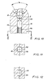
- an auxiliary slide 52 In the additional chamber 51, an auxiliary slide 52, the cross section of which is adapted, can be moved back and forth between a rear position (FIGS. 1, 2 and 10) and a front end position indicated by dash-dotted lines 53 in FIG. 10.
- the end face 54 of the auxiliary slide is shaped so that it forms part of the wall of the mixing chamber 2 in the advanced position. In the case of a cylindrical mixing chamber, the end face 54 of the auxiliary slide 52 is therefore part of a cylindrical surface.
- the additional chamber 51 can have a circular cross section 55, as can be seen in FIG. 11. However, it can also be advantageous to give the additional chamber 51 a prismatic cross section, in particular a square cross section. In FIG. 11, a square cross-section is indicated by dash-dotted lines 56, while FIG. 12 shows a rectangular cross-section 57.
- a hydraulic cylinder 58 with a piston 59 displaceable therein is provided for moving the auxiliary slide 52 (FIGS. 1 and 2).
- the pressure medium connections are labeled with the numbers 60 and 61.
- a state is assumed in each work cycle in which the ejection slide 4 is in the retracted position and the auxiliary slide 52 is advanced (dash-dot closing position 53 in FIG. 10).
- the auxiliary slide 52 is moved into the rear position by means of its drive 58, 59 moves so that the additional chamber 51 is released.
- This process can take place simultaneously with the opening of the mixing chamber inlets 27.
- This retraction movement of the auxiliary slide 52 is advantageously initiated somewhat before the inlets 27 are released.
- the above-mentioned processes are timed so that the initial mixture, at least with its essential part, initially remains in the additional chamber 51, while the further mixture formation then takes place essentially in the mixing chamber 2.
- the auxiliary slide 52 Towards the end of the mixing process, the auxiliary slide 52 is brought into its front closing position and pushes the mixture located in the additional chamber 51 into the mixing chamber. During this process, component material is expediently still injected into the mixing chamber through the inlets 27. In a device with valve assemblies V1 and V2 of the type described, this means that the valve elements are still in the injection position.
- the process can be ended.
- the processes can be assigned in time run differently.
- the procedure is particularly advantageous in such a way that the discharge slide 4 is first moved forward, and the valve elements 11 are only switched into the circulation position when the discharge slide 4 has covered the inlets 27. This also eliminates any danger that something in the mixture will enter or remain in the inlets 27.
- Lines 73 and 75 lead from a system (not shown) that contains one or more pumps and other components for supplying pressure medium that are common in a pressure medium supply system to directional valves 71 and 72 that can be actuated electromagnetically. Return lines from these are identified by the numbers 74 and 76.
- a line 78 leads from the directional control valve 71 to the connection 45 of the cylinder 42 and a line 77 to the connection 47 of the cylinder 40.
- the connections 60 and 61 of the cylinder 58 for the auxiliary slide 52 are connected to the directional control valve 72 via lines 79 and 80.
- Control lines leading from a central unit 81 to the directional control valves 71 and 72 are identified by the numbers 84 and 85.
- the central unit 81 has setting members 82 and actuating or switching elements 83, e.g. in the form of pushbuttons or the like, and also contains those facilities and components which are necessary or expedient for controlling the desired sequence of the described processes. These are available to the expert in detail.
- the timing and the assignment of the individual processes to one another can be made on the setting members 82 can be set, for example the switching times or the duration of the respective switching positions or operating states.
Landscapes
- Engineering & Computer Science (AREA)
- Mechanical Engineering (AREA)
- Processing And Handling Of Plastics And Other Materials For Molding In General (AREA)
Applications Claiming Priority (2)
| Application Number | Priority Date | Filing Date | Title |
|---|---|---|---|
| DE3709557 | 1987-03-24 | ||
| DE3709557A DE3709557C1 (de) | 1987-03-24 | 1987-03-24 | Vorrichtung zur Bildung eines Kunststoff-Reaktionsgemisches |
Publications (2)
| Publication Number | Publication Date |
|---|---|
| EP0283988A2 true EP0283988A2 (fr) | 1988-09-28 |
| EP0283988A3 EP0283988A3 (fr) | 1988-11-30 |
Family
ID=6323815
Family Applications (1)
| Application Number | Title | Priority Date | Filing Date |
|---|---|---|---|
| EP88104458A Withdrawn EP0283988A3 (fr) | 1987-03-24 | 1988-03-21 | Dispositif et procédé pour la fabricat d'un mélange réactif de matiere plastique |
Country Status (2)
| Country | Link |
|---|---|
| EP (1) | EP0283988A3 (fr) |
| DE (1) | DE3709557C1 (fr) |
Cited By (1)
| Publication number | Priority date | Publication date | Assignee | Title |
|---|---|---|---|---|
| EP1334308A4 (fr) * | 2000-11-06 | 2004-03-10 | Flexible Products Co | Distributeur de mousse a plusieurs composants comprenant un dispositif ameliore de regulation du debit |
Family Cites Families (8)
| Publication number | Priority date | Publication date | Assignee | Title |
|---|---|---|---|---|
| DE2024067A1 (en) * | 1969-05-29 | 1970-12-03 | VEB Plast- und Elastverarbeitungsmaschinen-Kombinat Karl-Marx-Stadt, χ 9000 Karl-Marx-Stadt | Mixer head with cleanable valve plastic - foam prodn |
| US3960506A (en) * | 1970-06-20 | 1976-06-01 | Bayer Aktiengesellschaft | Apparatus for producing homogeneous materials or foam from at least two inter-reacting components |
| DE2423631A1 (de) * | 1974-05-15 | 1975-12-11 | Hennecke Gmbh Maschf | Mischkopf fuer maschinen zur herstellung von mehrkomponentenkunststoffen, insbesondere schaumstoffen auf basis polyurethan |
| DE3136611A1 (de) * | 1981-07-22 | 1983-02-10 | Maschinenfabrik Hennecke Gmbh, 5090 Leverkusen | Einrichtung zum herstellen eines fliessfaehigen reaktionsgemisches aus mindestens zwei fliessfaehigen, miteinander zu massivstoff oder schaumstoff reagierenden komponenten |
| US4471887A (en) * | 1982-04-26 | 1984-09-18 | Component Management Corp. | Dispensing device |
| GB2126490B (en) * | 1982-07-09 | 1986-10-22 | Univ Manchester | Mixing head and actuator mechanism suitable therefor |
| DE3226412A1 (de) * | 1982-07-15 | 1984-01-19 | Maschinenfabrik Hennecke Gmbh, 5090 Leverkusen | Verfahren und mischkopf zum herstellen eines reaktionsgemisches aus mindestens zwei fliessfaehigen reaktionskomponenten |
| DE3323366C2 (de) * | 1983-06-29 | 1986-10-23 | Battenfeld Maschinenfabriken Gmbh, 5882 Meinerzhagen | Vorrichtung zum Erzeugen und Einleiten eines chemisch reaktionsfähigen Gemisches aus zwei Kunststoff-Komponenten in den Hohlraum einer Form |
-
1987
- 1987-03-24 DE DE3709557A patent/DE3709557C1/de not_active Expired
-
1988
- 1988-03-21 EP EP88104458A patent/EP0283988A3/fr not_active Withdrawn
Cited By (1)
| Publication number | Priority date | Publication date | Assignee | Title |
|---|---|---|---|---|
| EP1334308A4 (fr) * | 2000-11-06 | 2004-03-10 | Flexible Products Co | Distributeur de mousse a plusieurs composants comprenant un dispositif ameliore de regulation du debit |
Also Published As
| Publication number | Publication date |
|---|---|
| EP0283988A3 (fr) | 1988-11-30 |
| DE3709557C1 (de) | 1988-10-06 |
Similar Documents
| Publication | Publication Date | Title |
|---|---|---|
| DE2555156C3 (de) | Hochdruck-Mischkopf | |
| DE2502971C3 (de) | Vorrichtung zum Ausstoßen einer Mischung von Flüssigkeiten | |
| DE2607641A1 (de) | Hochdruck-mischkopf | |
| DE3120482C2 (de) | Vorrichtung zum Herstellen eines insbesondere chemisch reaktionsfähigen Kunststoffgemisches und zum Zuleiten desselben zu einer Form | |
| EP0360189A2 (fr) | Buse d'injection pour une machine à mouler par injection | |
| DE4206319C2 (de) | Nadelverschlußdüse mit Kolbenantrieb | |
| DE2413337B2 (de) | Mit einem Formwerkzeug kombinierte Mischeinrichtung | |
| DE3637823C2 (de) | Hilfskraftbetätigtes Spannfutter | |
| DE102005017413B4 (de) | Spritzgießdüse mit zwei Austrittsöffnungen | |
| DE2847504A1 (de) | Mischkopf zum mischen von wenigstens zwei fliessfaehigen materialkomponenten | |
| DE3427327C2 (fr) | ||
| DE2112535A1 (de) | Angussvorrichtung fuer die formgebende Verarbeitung von aus mehreren fluessigen Komponenten sich bildenden Kunststoffen,insbesondere von zellbildenden Kunststoffen | |
| EP0283988A2 (fr) | Dispositif et procédé pour la fabricat d'un mélange réactif de matiere plastique | |
| DE3427326C2 (fr) | ||
| DE3913681C1 (fr) | ||
| DE2127375C3 (de) | Doppeltwirkender Hydrozylinder, insbesondere für Werkzeugmaschinen | |
| DE2065057A1 (en) | Synth resin component mixer | |
| DE2262730C3 (de) | Vorrichtung zum dosierten Zuführen einer flüssigen Kunststoffkomponente in eine Mischkammer | |
| DE8704803U1 (de) | Vorrichtung zur Bildung eines Kunststoff-Reaktionsgemisches | |
| DE19722612C1 (de) | Vorrichtung zum Spritzgießen eines Werkstückes aus mindestens zwei unterschiedlichen Materialkomponenten | |
| DE2110270A1 (en) | Foundry blow moulding machine | |
| DE3117014A1 (de) | Vorrichtung zum erzeugen eines insbesondere schaeumfaehigen gemisches aus mindestens zwei vorzugsweise chemisch reaktionsfaehigen kunststoffkomponenten | |
| DE10005264C1 (de) | Verfahren und Vorrichtung zum Herstellen von Mehrkomponenten-Formteilen aus Kunststoff | |
| CH663927A5 (de) | Vorrichtung zum erzeugen und einleiten eines chemisch reaktionsfaehigen gemisches aus zwei kunststoff-komponenten in den hohlraum einer form. | |
| DE3617287A1 (de) | Vorrichtung zum erzeugen eines vorzugsweise chemisch reaktionsfaehigen gemisches aus mindestens zwei kunststoffkomponenten |
Legal Events
| Date | Code | Title | Description |
|---|---|---|---|
| PUAI | Public reference made under article 153(3) epc to a published international application that has entered the european phase |
Free format text: ORIGINAL CODE: 0009012 |
|
| AK | Designated contracting states |
Kind code of ref document: A2 Designated state(s): AT BE CH DE ES FR GB GR IT LI NL SE |
|
| PUAL | Search report despatched |
Free format text: ORIGINAL CODE: 0009013 |
|
| AK | Designated contracting states |
Kind code of ref document: A3 Designated state(s): AT BE CH DE ES FR GB GR IT LI NL SE |
|
| 17P | Request for examination filed |
Effective date: 19890529 |
|
| 17Q | First examination report despatched |
Effective date: 19900122 |
|
| STAA | Information on the status of an ep patent application or granted ep patent |
Free format text: STATUS: THE APPLICATION IS DEEMED TO BE WITHDRAWN |
|
| 18D | Application deemed to be withdrawn |
Effective date: 19911206 |