EP0284052B1 - Verfahren zur Erzeugung hochreinen Wassers und Verfahren zur Verwendung dieses Wassers - Google Patents
Verfahren zur Erzeugung hochreinen Wassers und Verfahren zur Verwendung dieses Wassers Download PDFInfo
- Publication number
- EP0284052B1 EP0284052B1 EP88104672A EP88104672A EP0284052B1 EP 0284052 B1 EP0284052 B1 EP 0284052B1 EP 88104672 A EP88104672 A EP 88104672A EP 88104672 A EP88104672 A EP 88104672A EP 0284052 B1 EP0284052 B1 EP 0284052B1
- Authority
- EP
- European Patent Office
- Prior art keywords
- water
- steam
- pure water
- tower
- superultra
- Prior art date
- Legal status (The legal status is an assumption and is not a legal conclusion. Google has not performed a legal analysis and makes no representation as to the accuracy of the status listed.)
- Expired - Lifetime
Links
- 238000000034 method Methods 0.000 title claims description 55
- 230000008569 process Effects 0.000 title claims description 49
- 229910021642 ultra pure water Inorganic materials 0.000 title description 35
- 239000012498 ultrapure water Substances 0.000 title description 35
- XLYOFNOQVPJJNP-UHFFFAOYSA-N water Substances O XLYOFNOQVPJJNP-UHFFFAOYSA-N 0.000 claims description 310
- 239000012528 membrane Substances 0.000 claims description 81
- 238000004821 distillation Methods 0.000 claims description 39
- 238000010438 heat treatment Methods 0.000 claims description 38
- 230000002209 hydrophobic effect Effects 0.000 claims description 32
- 238000005406 washing Methods 0.000 claims description 23
- 239000004065 semiconductor Substances 0.000 claims description 22
- 230000008016 vaporization Effects 0.000 claims description 21
- 238000009835 boiling Methods 0.000 claims description 20
- 239000007789 gas Substances 0.000 claims description 17
- 244000005700 microbiome Species 0.000 claims description 16
- XUIMIQQOPSSXEZ-UHFFFAOYSA-N Silicon Chemical compound [Si] XUIMIQQOPSSXEZ-UHFFFAOYSA-N 0.000 claims description 15
- 229910052710 silicon Inorganic materials 0.000 claims description 15
- 239000010703 silicon Substances 0.000 claims description 15
- 238000001704 evaporation Methods 0.000 claims description 11
- 239000007921 spray Substances 0.000 claims description 11
- 238000001816 cooling Methods 0.000 claims description 10
- 239000010419 fine particle Substances 0.000 claims description 10
- 230000008020 evaporation Effects 0.000 claims description 9
- 238000001223 reverse osmosis Methods 0.000 claims description 9
- 229920006395 saturated elastomer Polymers 0.000 claims description 8
- 238000007599 discharging Methods 0.000 claims description 7
- 229910052799 carbon Inorganic materials 0.000 claims description 5
- 239000011261 inert gas Substances 0.000 claims description 5
- OKTJSMMVPCPJKN-UHFFFAOYSA-N Carbon Chemical compound [C] OKTJSMMVPCPJKN-UHFFFAOYSA-N 0.000 claims description 4
- 230000001464 adherent effect Effects 0.000 claims description 4
- 230000001590 oxidative effect Effects 0.000 claims description 4
- 229940079593 drug Drugs 0.000 claims description 3
- 239000003814 drug Substances 0.000 claims description 3
- 239000012466 permeate Substances 0.000 claims description 3
- 230000008021 deposition Effects 0.000 claims description 2
- 235000012431 wafers Nutrition 0.000 description 57
- 239000000126 substance Substances 0.000 description 44
- 239000010408 film Substances 0.000 description 34
- CURLTUGMZLYLDI-UHFFFAOYSA-N Carbon dioxide Chemical compound O=C=O CURLTUGMZLYLDI-UHFFFAOYSA-N 0.000 description 28
- 230000003647 oxidation Effects 0.000 description 24
- 238000007254 oxidation reaction Methods 0.000 description 24
- 239000012535 impurity Substances 0.000 description 20
- 239000000758 substrate Substances 0.000 description 19
- 238000001035 drying Methods 0.000 description 18
- 229910002092 carbon dioxide Inorganic materials 0.000 description 16
- 238000010586 diagram Methods 0.000 description 15
- 238000009834 vaporization Methods 0.000 description 15
- VYPSYNLAJGMNEJ-UHFFFAOYSA-N Silicium dioxide Chemical compound O=[Si]=O VYPSYNLAJGMNEJ-UHFFFAOYSA-N 0.000 description 14
- 229960004424 carbon dioxide Drugs 0.000 description 12
- 239000001569 carbon dioxide Substances 0.000 description 12
- 238000004519 manufacturing process Methods 0.000 description 11
- 239000007788 liquid Substances 0.000 description 10
- 150000003839 salts Chemical class 0.000 description 9
- NWUYHJFMYQTDRP-UHFFFAOYSA-N 1,2-bis(ethenyl)benzene;1-ethenyl-2-ethylbenzene;styrene Chemical compound C=CC1=CC=CC=C1.CCC1=CC=CC=C1C=C.C=CC1=CC=CC=C1C=C NWUYHJFMYQTDRP-UHFFFAOYSA-N 0.000 description 8
- 239000000498 cooling water Substances 0.000 description 8
- 239000003456 ion exchange resin Substances 0.000 description 8
- 229920003303 ion-exchange polymer Polymers 0.000 description 8
- 238000010276 construction Methods 0.000 description 7
- 239000003595 mist Substances 0.000 description 7
- 239000000377 silicon dioxide Substances 0.000 description 7
- 229910052681 coesite Inorganic materials 0.000 description 5
- 229910052906 cristobalite Inorganic materials 0.000 description 5
- 238000007598 dipping method Methods 0.000 description 5
- -1 polyethylene Polymers 0.000 description 5
- 235000012239 silicon dioxide Nutrition 0.000 description 5
- 229910052682 stishovite Inorganic materials 0.000 description 5
- 238000012546 transfer Methods 0.000 description 5
- 229910052905 tridymite Inorganic materials 0.000 description 5
- 238000011084 recovery Methods 0.000 description 4
- 230000008929 regeneration Effects 0.000 description 4
- 238000011069 regeneration method Methods 0.000 description 4
- 238000000108 ultra-filtration Methods 0.000 description 4
- 230000015572 biosynthetic process Effects 0.000 description 3
- 238000011109 contamination Methods 0.000 description 3
- 230000002070 germicidal effect Effects 0.000 description 3
- 230000001965 increasing effect Effects 0.000 description 3
- 239000000463 material Substances 0.000 description 3
- 229910052751 metal Inorganic materials 0.000 description 3
- 239000002184 metal Substances 0.000 description 3
- 239000002245 particle Substances 0.000 description 3
- 238000005498 polishing Methods 0.000 description 3
- 238000002203 pretreatment Methods 0.000 description 3
- QGZKDVFQNNGYKY-UHFFFAOYSA-N Ammonia Chemical compound N QGZKDVFQNNGYKY-UHFFFAOYSA-N 0.000 description 2
- PXHVJJICTQNCMI-UHFFFAOYSA-N Nickel Chemical compound [Ni] PXHVJJICTQNCMI-UHFFFAOYSA-N 0.000 description 2
- 239000004698 Polyethylene Substances 0.000 description 2
- 239000004743 Polypropylene Substances 0.000 description 2
- 230000015556 catabolic process Effects 0.000 description 2
- 238000009833 condensation Methods 0.000 description 2
- 230000005494 condensation Effects 0.000 description 2
- 230000007423 decrease Effects 0.000 description 2
- 230000006866 deterioration Effects 0.000 description 2
- 238000001914 filtration Methods 0.000 description 2
- 239000011521 glass Substances 0.000 description 2
- 150000002500 ions Chemical class 0.000 description 2
- 238000001471 micro-filtration Methods 0.000 description 2
- 239000000203 mixture Substances 0.000 description 2
- 230000003287 optical effect Effects 0.000 description 2
- 229920000573 polyethylene Polymers 0.000 description 2
- 229920001155 polypropylene Polymers 0.000 description 2
- 229920001343 polytetrafluoroethylene Polymers 0.000 description 2
- 239000011148 porous material Substances 0.000 description 2
- 238000001556 precipitation Methods 0.000 description 2
- 238000002360 preparation method Methods 0.000 description 2
- 239000000047 product Substances 0.000 description 2
- 238000012360 testing method Methods 0.000 description 2
- 239000010409 thin film Substances 0.000 description 2
- 238000011282 treatment Methods 0.000 description 2
- 241000894006 Bacteria Species 0.000 description 1
- BVKZGUZCCUSVTD-UHFFFAOYSA-M Bicarbonate Chemical compound OC([O-])=O BVKZGUZCCUSVTD-UHFFFAOYSA-M 0.000 description 1
- 239000004215 Carbon black (E152) Substances 0.000 description 1
- BVKZGUZCCUSVTD-UHFFFAOYSA-L Carbonate Chemical compound [O-]C([O-])=O BVKZGUZCCUSVTD-UHFFFAOYSA-L 0.000 description 1
- CBENFWSGALASAD-UHFFFAOYSA-N Ozone Chemical compound [O-][O+]=O CBENFWSGALASAD-UHFFFAOYSA-N 0.000 description 1
- 239000004695 Polyether sulfone Substances 0.000 description 1
- 238000000862 absorption spectrum Methods 0.000 description 1
- 239000002253 acid Substances 0.000 description 1
- 230000009471 action Effects 0.000 description 1
- 230000002411 adverse Effects 0.000 description 1
- 230000002776 aggregation Effects 0.000 description 1
- 238000004220 aggregation Methods 0.000 description 1
- 239000003513 alkali Substances 0.000 description 1
- 229910052782 aluminium Inorganic materials 0.000 description 1
- XAGFODPZIPBFFR-UHFFFAOYSA-N aluminium Chemical compound [Al] XAGFODPZIPBFFR-UHFFFAOYSA-N 0.000 description 1
- 229910021529 ammonia Inorganic materials 0.000 description 1
- QVGXLLKOCUKJST-UHFFFAOYSA-N atomic oxygen Chemical compound [O] QVGXLLKOCUKJST-UHFFFAOYSA-N 0.000 description 1
- 230000001580 bacterial effect Effects 0.000 description 1
- BVKZGUZCCUSVTD-UHFFFAOYSA-N carbonic acid Chemical compound OC(O)=O BVKZGUZCCUSVTD-UHFFFAOYSA-N 0.000 description 1
- 230000008859 change Effects 0.000 description 1
- 239000011248 coating agent Substances 0.000 description 1
- 238000000576 coating method Methods 0.000 description 1
- 230000000052 comparative effect Effects 0.000 description 1
- 230000007547 defect Effects 0.000 description 1
- 230000002950 deficient Effects 0.000 description 1
- 238000011033 desalting Methods 0.000 description 1
- 238000013461 design Methods 0.000 description 1
- 238000004090 dissolution Methods 0.000 description 1
- 239000000428 dust Substances 0.000 description 1
- 230000000694 effects Effects 0.000 description 1
- 230000005611 electricity Effects 0.000 description 1
- 230000003028 elevating effect Effects 0.000 description 1
- 238000002474 experimental method Methods 0.000 description 1
- 238000011010 flushing procedure Methods 0.000 description 1
- 239000008214 highly purified water Substances 0.000 description 1
- 229930195733 hydrocarbon Natural products 0.000 description 1
- 150000002430 hydrocarbons Chemical class 0.000 description 1
- 125000001165 hydrophobic group Chemical group 0.000 description 1
- 230000006872 improvement Effects 0.000 description 1
- 239000002198 insoluble material Substances 0.000 description 1
- 239000011810 insulating material Substances 0.000 description 1
- 230000010354 integration Effects 0.000 description 1
- 238000005342 ion exchange Methods 0.000 description 1
- 238000012423 maintenance Methods 0.000 description 1
- 238000005259 measurement Methods 0.000 description 1
- 230000007246 mechanism Effects 0.000 description 1
- 229910021645 metal ion Inorganic materials 0.000 description 1
- 150000001455 metallic ions Chemical class 0.000 description 1
- 229910052759 nickel Inorganic materials 0.000 description 1
- 230000003204 osmotic effect Effects 0.000 description 1
- 238000013021 overheating Methods 0.000 description 1
- 229910052760 oxygen Inorganic materials 0.000 description 1
- 239000001301 oxygen Substances 0.000 description 1
- 238000011056 performance test Methods 0.000 description 1
- 230000000737 periodic effect Effects 0.000 description 1
- 238000007747 plating Methods 0.000 description 1
- 229920002492 poly(sulfone) Polymers 0.000 description 1
- 229920006393 polyether sulfone Polymers 0.000 description 1
- 229920000098 polyolefin Polymers 0.000 description 1
- 239000004810 polytetrafluoroethylene Substances 0.000 description 1
- 230000002265 prevention Effects 0.000 description 1
- 230000009467 reduction Effects 0.000 description 1
- 239000011347 resin Substances 0.000 description 1
- 229920005989 resin Polymers 0.000 description 1
- 230000002441 reversible effect Effects 0.000 description 1
- 238000000926 separation method Methods 0.000 description 1
- 229920002050 silicone resin Polymers 0.000 description 1
- 239000002904 solvent Substances 0.000 description 1
- 238000001179 sorption measurement Methods 0.000 description 1
- 230000003068 static effect Effects 0.000 description 1
- 230000001954 sterilising effect Effects 0.000 description 1
- 238000004659 sterilization and disinfection Methods 0.000 description 1
- 238000003860 storage Methods 0.000 description 1
- 238000007740 vapor deposition Methods 0.000 description 1
Images


Classifications
-
- B—PERFORMING OPERATIONS; TRANSPORTING
- B01—PHYSICAL OR CHEMICAL PROCESSES OR APPARATUS IN GENERAL
- B01D—SEPARATION
- B01D61/00—Processes of separation using semi-permeable membranes, e.g. dialysis, osmosis or ultrafiltration; Apparatus, accessories or auxiliary operations specially adapted therefor
- B01D61/36—Pervaporation; Membrane distillation; Liquid permeation
- B01D61/364—Membrane distillation
-
- B—PERFORMING OPERATIONS; TRANSPORTING
- B01—PHYSICAL OR CHEMICAL PROCESSES OR APPARATUS IN GENERAL
- B01D—SEPARATION
- B01D3/00—Distillation or related exchange processes in which liquids are contacted with gaseous media, e.g. stripping
- B01D3/06—Flash distillation
-
- C—CHEMISTRY; METALLURGY
- C02—TREATMENT OF WATER, WASTE WATER, SEWAGE, OR SLUDGE
- C02F—TREATMENT OF WATER, WASTE WATER, SEWAGE, OR SLUDGE
- C02F1/00—Treatment of water, waste water, or sewage
- C02F1/02—Treatment of water, waste water, or sewage by heating
- C02F1/04—Treatment of water, waste water, or sewage by heating by distillation or evaporation
- C02F1/045—Treatment of water, waste water, or sewage by heating by distillation or evaporation for obtaining ultra-pure water
-
- C—CHEMISTRY; METALLURGY
- C02—TREATMENT OF WATER, WASTE WATER, SEWAGE, OR SLUDGE
- C02F—TREATMENT OF WATER, WASTE WATER, SEWAGE, OR SLUDGE
- C02F2103/00—Nature of the water, waste water, sewage or sludge to be treated
- C02F2103/02—Non-contaminated water, e.g. for industrial water supply
- C02F2103/04—Non-contaminated water, e.g. for industrial water supply for obtaining ultra-pure water
-
- Y—GENERAL TAGGING OF NEW TECHNOLOGICAL DEVELOPMENTS; GENERAL TAGGING OF CROSS-SECTIONAL TECHNOLOGIES SPANNING OVER SEVERAL SECTIONS OF THE IPC; TECHNICAL SUBJECTS COVERED BY FORMER USPC CROSS-REFERENCE ART COLLECTIONS [XRACs] AND DIGESTS
- Y10—TECHNICAL SUBJECTS COVERED BY FORMER USPC
- Y10S—TECHNICAL SUBJECTS COVERED BY FORMER USPC CROSS-REFERENCE ART COLLECTIONS [XRACs] AND DIGESTS
- Y10S210/00—Liquid purification or separation
- Y10S210/90—Ultra pure water, e.g. conductivity water
Definitions
- the invention relates to a process for producing superultra-pure water from raw water in the form of service water or reverse osmosis water or the like, containing volatile and non-volatile components and pre-treated in order to prevent deposition of scale.
- Such volatile substances are mostly carbondioxide gas components in the form of H2CO3, HCO3 ⁇ , CO32 ⁇ , organic substances and the like.
- the non-volatile substances are usually fine particles, microorganisms and the like.
- Figure 12 illustrates a prior art apparatus for producing ultra-pure water.
- the raw water is subjected to pre-treatments such as aggregation and precipitation, filtration, microfiltration, etc., after which it is sent to a step of reverse osmosis (RO) where the major part of soluble organic components and 90 to 99% of the inorganic salts present in the raw water are removed.
- RO reverse osmosis
- the water having permeated the RO membrane is then decarbonated in the deaerating tower, after which it is sent to the ion exchange resin step.
- the ion exchange resin tower is of two bed/mixed bed regeneration type. In this step, salts are completely removed, and usually a primary pure water having a specific resistance of 10 M ⁇ cm or above is obtained in this step and stored in a pure water tank.
- the pure water is further treated with mixed bed type polishing ion exchange resin to remove impurities more completely. Then, it is made free from microorganisms in the ultra-violet germicidal step and then made free from the residual fine particles and dead microorganisms in the ultrafiltration (UF) step to give an ultra-pure water.
- Japanese Patent Application Kokai (Laid-Open) No. 230,703/86 discloses a pure-water producing apparatus, an inner space of which is partitioned by a hydrophobic porous membrane which is permeable to vapor of liquids and impermeable to liquids themselves, and one side is used as the path of raw water, while the other side is provided with a cooling plate.
- the space between the cooling plate and the hydrophobic porous membrane is used as a condensing chamber, and outside of the cooling plate is used as the path of cooling water.
- the apparatus at least has a separating membrane unit for condensing the vapor supplied from the raw water path and having passed the porous membrane in the condensing chamber and a heat tank having a heater.
- a raw water (e.g. service water or the like) is led to the cooling water path of the separating membrane unit, and the raw water having passed the cooling water path is further led to the heat tank, and the raw water having been heated in the heat tank to a high temperature is led to the raw water path of the separating membrane unit, by pipings.
- a raw water e.g. service water or the like
- the above-mentioned prior art involves many elementary instruments such as filter membranes, ion exchange resin, germicidal lamp and the like, and improvement in the water quality of the resulting ultra-pure water necessarily requires to improve the quality of the elementary instruments.
- the existing membrane module systems there are a number of requirements as follows.
- the surface of the membrane having a separating performance must be free from defect, and the water having permeated the membrane must be perfectly sealed from raw water.
- the module must be so constructed that it involves no part allowing the residence of liquid and all the parts of module must be thoroughly washable to prevent the growth of bacteria.
- the quantity of substances dissolving out of the module must be as small as possible.
- a special grade of membrane module is used for production of ultra-pure water.
- US-A-3 418 214 discloses a flash evaporator comprising a vessel in the inlet section of which an impure liquid like salt water is flash evaporated thereby releasing air and non-condensable gases from the salt water.
- the salt water drops down in said first section in contact with a flow of steam for further heating and driving out air.
- the salt water arriving at the bottom of the vessel is mixed with preheated water. Because of pressure difference steam is produced, part of which flows into the first section as mentioned above and part of which flows through a demister for retaining droplets into a condensing section, from which pure water is discharged.
- a substantial portion of the air and non-condensable gases are vented.
- the described system does not disclose a hydrophobic porous membrane, only a demister. Further, all the equipment is mounted in one and the same vessel, the first section being in connection with the second section by the inlet for the steam from the second section for contacting the salt water droplets in said first section. With this device volatile substances are transferred into the condensing section and into the condensed water.
- US-A-3 726 234 describes a steam generator provided with a heat means and a discharge tube in its upper part opening to a receiver.
- the tube is surrounded on part of its length by condensed liquid kept near the boiling point. Included vaporizable substances will thereby be sufficiently vaporized from said liquid.
- the steam flows from the steam generator into the tube through a mist separator means made of porous materials such as sintered metal, porcelaine and others.
- the mist separator is constructed so as to prevent boiling splashes or mist from entering said receiver.
- the receiver opens into a condenser.
- the liquid in the receiver is passed through a gas remover into a storage for the distillate. Even if this apparatus is used for producing highly purified water, there is no hydrophobic porous membrane.
- the mist separation means is disposed in the first vessel, which is the steam generator.
- This object is achieved by a process comprising the steps of heating and boiling the raw water in a first tower, thereby vaporizing off the volatile components; discharging the vaporized volatile components together with steam from said first tower; transferring the raw water free of volatile components to a second tower; heating the raw water free of volatile components in said second tower such that steam is generated; contacting the steam generated in said second tower with a hydrophobic porous gas-permeable and liquid-impermeable membrane to make the steam permeate the membrane and to separate the metallic components containing mists of tiny droplets accompanying the steam; and condensing the steam to superultra-pure water having a specific resistance of 18 M ⁇ cm or above, a total organic carbon content of not more than 20 x 10 ⁇ 3 ppm, 12 or less fine particles per ml with a size of 0.1 ⁇ m or above and alive microorganisms undetectable.
- the steam having permeated the membrane is lead into an atmosphere of saturated steam or of inert gas in which atmosphere the steam is condensed.
- the raw water is kept under a reduced pressure in said first tower during its boiling for vaporizing off the volatile components.
- the raw water from which the volatile components were vaporized off in the first tower is heated in said second tower in heat exchange with the steam discharged together with the vaporized volatile components from said first tower.
- the volatile components are removed from said raw water in said first tower by flash evaporation of the raw water.
- the apparatus for producing superultra-pure water comprises a first volatile component-removing tower equipped with means for heating and boiling the raw water containing volatile and non-volatile components, with means for discharging the vaporized volatile components formed by said heating and with means for transferring the raw water, from which the volatile components are vaporized off, from said first tower to at least one second distillation tower equipped with a heat source for heating the transferred raw water such that steam is generated, a hydrophobic porous gas-permeable and liquid-impermeable membrane associated with each distillation tower with which membrane the steam generated in said second tower is contacted, cooling means for condensing the steam having permeated said membrane to the superultra-pure water and discharge means for the condensed superultra-pure water.
- the hydrophobic porous gas-permeable and liquid-impermeable membrane is mounted inside of the distillation tower.
- the cooling means for condensing the steam having permeated said membrane is mounted inside of the distillation tower.
- said means for discharging the vaporized volatile components formed by said heating in the first volatile component removing tower are connected with means for heat exchange in said distillation tower to act at least partly as the heat source for generating steam in said distillation tower.
- said means for heating and boiling raw water containing volatile and non-volatile components are a heater and a spray nozzle for flash evaporation.
- a gas supply means is provided for making the atmosphere for condensing the steam in the distillation tower an atmosphere of saturated steam or of inert gas.
- the said volatile component removing tower can be equipped with a pressure reducing means.
- the superultra-pure water produced according to the invention is used for washing semiconductor integrated circuits, for washing medical tools, for producing medical drugs or for oxidizing the silicon surface of a semiconductor wafer by contacting said silicon surface with the superultra-pure water.
- the thickness of the oxide film is controlled by changing the temperature of the superultra-pure water and/or the contact time with the superultra-pure water. Further, the surface contacted with superultra-pure water can be dried by evaporating the adherent superultra-pure water with a controlled vaporizing speed.
- the superultra-pure water of the invention is advantageously usable for washing LSI as with increasing temperature water decreases its surface tension and increases affinity to substrate and undergoes a smaller influence by static electricity, in its nature.
- the water obtained according to the invention is quite low in the content of impurities, so that it can relax the problems in the washing of LSI, such as difficulty in formation of desired LSI pattern, increase in leakage current or pn junction, deterioration in pressure resistance of gate oxide film, etc. and thereby it enables to improve the yield and characteristics of LSI.
- the present invention there is obtained a high temperature superultra-pure water containing microorganisms at all or hardly containing microorganisms. Even if it contains microorganisms, their growth can be suppressed to a marked extent by maintaining the water at a high temperature.
- the superultra-pure water of the invention is quite effectively usable for washing medical tools and producing medical drugs.
- service water and reverse osmosis-treated water contain various inorganic substances, ions, organic substances and microorganisms in a large amount.
- volatile substances which cannot be removed by distillation carbon dioxide components, volatile organic and inorganic components, ammonia, SO3, etc.
- the raw water from which the volatile components have been removed are further heated to generate steam. Since volatile components have already been removed, this steam has a considerably high purity.
- the steam is further passed through hydrophobic porous membrane, whereby the accompanying water droplets (mists) are removed, and there is obtained a high purity steam containing no impurities other than water.
- the superultra-pure water having a high purity and containing no impurities such as ions, organic substances, fine particules and alive microorganisms. Further, by condensing the steam having passed the hydrophobic porous membrane in an atmosphere of saturated steam or inert gas, pollution from the air can be prevented.
- hydrophobic porous membrane membranes of polyolefins (e.g. polyethylene, polypropylene and the like), polysulfone, polyether sulfone, silicone resin, fluororesin and the like can be used, for example, as mentioned in Japanese Patent Application Kokai (Laid-Open) No. 118,284/85.
- the hydrophobic porous membrane should satisfy the conditions mentioned in Japanese Patent Application Kokai (Laid-Open) No. 118,284/85.
- Si surface is much richer than SiO2 surface in activity, so that it takes various polluting components into itself from media contacted with it. If an Si substrate having taken-in the polluting components is oxidized to form SiO2 film on its surface, the SiO2 film is bad in film quality, so that insulating resistance of the wafer is deteriorated.
- the taking-in of the pollution occurs when the wafer is exposed to the air in clean room in the course of transporting the wafer from the drying step (the final step of washing process) to the oxidation process. As a measure for preventing it, the wafer is oxidized in the superultra-pure water whereby, a very thin oxide film of high quality can be formed.
- the water quality can be evaluated by dropping a predetermined quality of test water onto Si wafer, drying up the water and observing the residue on the wafer (called "water mark").
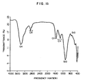
- FIG. 17 illustrates the infrared absorption spectrum of the water mark of superultra-pure water dried at ordinary temperature, where all the peaks demonstrate that the water mark is a hydrocarbon type substance except for the OH peak due to the water absorbed into KBr at the time of sample preparation and the SiO peak derived from the Si substrate (a part of substrate surface is scraped off when water mark is taken from Si substrate).
- the impurities in superultra-pure water belong to almost one series of substances having neither hydrophilic group nor hydrophobic group. From the viewpoint of adsorption, this exercises a good influence on the film quality at the time of forming SiO2 film.
- water mark Since water mark has the above-mentioned properties, water mark is difficult to observe by SEM etc. where the sample is exposed to vacuum or high temperature.
- prior-art ultra-pure water contains no detectable silica (JIS K 0101).
- silica dissociates to a very slight extent and combines with the Si of surface having dangling bond, due to which the quality of formed oxide film is deteriorated.
- the fatty substances adhering to the surface of semiconductor wafer are washed away with a solvent and metallic impurities are washed away with acid and alkali, successively.
- the chemical solution adhering to the surface of semiconductor wafer is washed away with prior-art ultra-pure water.
- a hydrophilic thin film of oxide is formed on the surface of semiconductor wafer with the dissolved oxygen in water in a superultra-pure water containing no metallic ions exercising adverse influence on the semiconductor which has been prepared by making a steam permeate a hydrophobic porous membrane to remove the mists containing metallic components and then condensing it.
- the water adhering to the thin oxide film formed on the surface of semiconductor wafer is dehydrated and dried.
- an oxide film is additionally formed on the thin oxide film on the semiconductor wafer in an oxidation furnace.
- the thin film-forming technique is largely adopted.
- SiO2 film is formed on Si substrate by oxidation and a thin film of insulating material or metal such as aluminum is formed by vapor deposition.
- a film of metal such as nickel is formed on substrate by plating or a film of photosensitive material is formed by coating.
- the substrate surface can be washed with the superultra-pure water according to the invention and then brought into dryness as a pre-treatment.
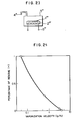
- heat is transferred by using a heating element placed in a clean atmosphere as the heat transfer surface to maintain a temperature not causing any violent boiling at the interface between substrate surface and adherent water and not bringing about dryness. That is, overheating can be prevented by controlling the temperature so as not to exceed the saturation temperature of water. If the temperature of heating is too low, the vaporization progresses very slowly and dissolved substances having a boiling point higher than that temperature are deposited. Accordingly, it is an indispensable condition to maintain an appropriate velocity of vaporization. This vaporization velocity is proportional to the temperature of substrate (i.e. heat transfer surface)/or the temperature difference at the boundary layer.
- the substrate temperature should be adjusted to a temperature close to the uppermost boiling point of dissolved organic substances and boiling point of water to keep an appropriate velocity of vaporization.
- the vaporization velocity is preferably about 4 g/hour or above.
- the present invention is by no means limited by these examples.
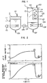
- FIG. 1 illustrates a fundamental example of the present invention.
- This apparatus is constructed of volatile component-removing tower 2 having raw water heater 110 and vapor discharging hole 112, membrane distillation tower 1 having raw water heater 108, hydrophobic porous membrane 101 and condensing surface 113, raw water piping 114 connecting between the volatile component removing tower and the membrane distillation tower, and pump 106 for sending raw water provided in the middle of said piping.
- Raw water 111 to be treated is introduced into the volatile component removing tower 2 and heated and boiled by raw water heater 110, whereby the carbon dioxide gas and volatile organic substances in the raw water are vaporized and discharged from vapor outlet 112 out of the system together with steam.
- the raw water from which the dissolved carbon dioxide gas and volatile organic substances have been removed is then sent into membrane distillation tower 1 by water supply pump 106.
- the raw water having entered membrane distillation tower 1 is again heated by raw water heater 108 and vaporized.
- the steam (arrow 15) generated by the vaporization is filtered with hydrophobic porous membrane 101, condensed on the condensing surface 113 cooled by the flowing cooling water 103, i.e. on the surface of cooling water piping, and taken out as formed superultra-pure water 104.
- the cooling means is constructed of cooling water 103 and condensing surface 113.
- the major part of the steam passing hydrophobic porous membrane is made into superultra-pure water, its minor part is blown out from valve 102 in order to remove the uncondensable gases in the system.
- the raw water is also blown out from respective drain valve 107 and 109, preferably. Since in this apparatus the carbon dioxide gas components and volatile organic substances present in raw water can be removed in the fore stage of membrane distillation tower, a superultra-pure water of high purity can be produced.
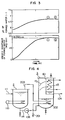
- Figure 2 illustrates specific resistance and pH of formed water produced by feeding a raw water (reverse osmosis-treated water) into membrane distillation tower, for comparison with example of the present invention.
- Figure 3 illustrates those in this example.
- (1) means the point at which feeding of water into membrane distillation tower is started, and (2) means the point at which the feeding of raw water is stopped.
- (1) means the point at which feeding of water into membrane distillation tower is started, and (2) means the point at which the feeding of raw water is stopped.
- Figure 2 where the raw water does not pass volatile component removing tower specific resistance of formed water descends to a few M ⁇ cm simultaneously with the start of water feed.
- the number of fine particles having a particle size of 0.1 ⁇ m or above was 10 or less per 1 mm3, and the total organic carbon content (TOC) was 10 ppb.
- water marks were prepared on silicon wafer, and they were compared with each other.
- the term "water mark” means a residue formed by dropping one drop of water on a silicon wafer and drying it up.
- the formed water of the apparatus of the invention gave a considerably smaller quantity of residue, demonstrating its high purity.
- the merit of the apparatus of the invention was exhibited more evidently.
- the drying was carried out at high temperature, the water mark appearing at ordinary temperature completely disappeared and nothing was observable on the silicon wafer.
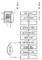
- FIG. 4 illustrates another example of the present invention.
- This apparatus is constructed of volatile component removing tower 2 having raw water heater 110, heat exchanger for heating raw water 202, membrane distillation tower 3 having hydrophobic porous membrane 101 and condensing surface 113, and water feeding pump 106 for transporting raw water between them.
- the raw water to be treated 111 is introduced into volatile component removing tower 2, where it is heated and boiled by raw water heater 110 to vaporize the carbon dioxide gas and volatile organic substances present in it and discharges them out of the system from vapor outlet 203.
- the raw water from which the dissolved carbondioxide gas components and volatile organic substances have been removed is sent to membrane distillation tower 3 by feeding pump 106.
- the raw water having entered the membrane distillation tower 3 is again heated and vaporized by the heat exchanger for heating raw water 202.
- the heating medium in the heat exchanger for heating raw water 202 is the steam generated in volatile component removing tower 2. After releasing its latent heat, the resulting liquid water is discharged out of the system from outlet 201 of heat exchanger.
- the steam (arrow 15) generated by the heating action of heat exchanger for heating raw water 202 passes hydrophobic porous membrane 101 where the accompanying mists are removed, after which the steam is condensed on the condensing surface 113 and taken out of the system as formed water 104, i.e. as a superultra-pure water.
- This apparatus is constructed of volatile component removing tower 4 having spray pump 301, raw water heater 302 and spray nozzle 303 and membrane distillation tower 3.
- the raw water to be treated 111 is introduced into the suction side of spray pump 301 and pressurized by the pump, after which it is heated by raw water heater 302 to a temperature a few degrees (e.g. 5-10°C) higher than the saturated temperature in the volatile component removing tower and then discharged into the system from spray nozzle 303.
- the intermediate part from pump 301 to spray nozzle 303 must be pressurized up to a pressure not lower than the saturated pressure at the temperature to which the raw water heater 302 has elevated, and vaporization (boiling) in piping must be prevented.
- the raw water sprayed from spray nozzle 303 is rapidly heated to the inner temperature of volatile component removing tower 4 and vaporized to form steam.
- the carbon dioxide gas components and low-boiling organic components dissolved in the raw water are also gasified simultaneously and released into gas phase.
- the liquid staying in the volatile component removing tower 4 without vaporization is again led to spray pump 301, where it is subjected to flash evaporation.
- the steam generated herein, carbon dioxide gas components and low-boiling organic components are taken out of the system from steam outlet 203, sent into heat exchanger for heating raw water 202 of membrane distillation tower 3 and utilized as a heat source of membrane distillation.
- the raw water treated in volatile component removing tower 4 is sent into membrane distillation tower 3 by feeding pump 106.
- raw water is fed into the suction side of spray pump 301, and it is overheated above its boiling point by raw water heater 302 before being fed into volatile component removing tower 4 and flash-evaporated from spray nozzle 303. Accordingly, the raw water passes the step of flash evaporation at least once before being introduced into feeding pump 106 leading to membrane distillation tower 3, so that feeding of untreated raw water into membrane distillation tower 3 is prevented.
- Figure 6 illustrates one example of multi-state process devised with consideration of the cost of formed water.
- the raw water which has been made free from carbon dioxide gas components and volatile TOC components by flash evaporation in volatile component removing tower 4 is sent into the first membrane distillation tower 5. Since the first membrane distillation tower 5 is in a saturated state at a lower pressure and a lower temperature than in volatile component removing tower 4, the raw water can be sent into the first membrane distillation tower 5 by merely operating valve 414.
- the latent heat of steam 410 generated in volatile component removing tower 4 is utilized for heating the raw water in the first membrane distillation tower 5.
- the steam 411 generated in the first membrane distillation tower is separated from mist when it passes through hydrophobic porous membrane 105, after which it passes piping 411 and is utilized for heating the raw water in the second membrane distillation tower.
- the steam having released its latent heat for heating the second membrane distillation tower returns to liquid water, which is discharged out of the system from heat exchanger outlet 413.
- the final step of this multi-stage process is provided with a simple condenser 7 where the generated high purity steam is condensed to give an superultra-pure water. Since the final stage is worked in the neighborhood of atmospheric pressure, the withdrawal of the formed water is prevented from contamination by dust formation in sliding parts such as pumps and the like.
- Figure 12 illustrates an outlined view of prior apparatus for producing ultra-pure water.
- the raw water is subjected to pre-treatments such as coagulation-precipitation, filtration, microfiltration, etc. and then sent to the step of reverse osmosis (RO) where the major part of dissolved organic components and about 90% of inorganic salts present in the raw water are removed.
- RO reverse osmosis
- the reverse osmosis water is decarbonated in deaerating tower and sent to ion exchange resin step.
- vacuum deaerating tower is usually used as the deaerating apparatus
- a deaerating module using hydrophobic porous membrane is also devised for this purpose (for example, see: Japanese Patent Application Kokai (Laid-Open) No. 118,284/85).
- the ion exchange tower is of two bed/mixed bed regeneration type. In this step, salts are completely removed, and usually a primary pure-water having a specific resistance of 10 M ⁇ cm or above is obtained.
- the primary pure water is once stored in a pure water tank. Then, it is treated in a mixed bed type polishing ion exchange resin tower to remove the impurities further completely, after which alive microorganisms are eliminated in a ultraviolet germicidal step and then the residual fine particles and dead microorganisms are removed by ultrafiltration (UF) to give an ultra-pure water.
- UF ultrafiltration
- water quality of the ultra-pure water produced by the use of this prior-art apparatus is as follows: number of microorganism 0.05/ml; number of fine particles having a size of 0.1 ⁇ m or above 50 to 100 particles/ml; TOC 100 ppb; electrical specific resistance 18 m ⁇ cm.
- FIG 8 is the fundamental flow diagram of the present invention.
- a raw water such as service water is pre-treated by means of RO or the like in order to prevent the scaling in steam generater.
- the pre-treated water is sent into a steam generater where the volatile substances are removed.
- the steam free from volatile substances is sent in the state of steam into a clean room via a clean piping and enters a condenser placed in the neighborhood of use point.
- the steam is condensed and formed into an superultra-pure water.
- FIG 9 illustrates one example of the outlined view of the steam generater.
- the pre-treated raw water 20 enters de-CO2 de-TOC part 21 where it is boiled with heater 23 to remove CO2 and TOC components together with steam. Though a direct heating is adopted in this example, other methods such as flash evaporation and the like are also usable.
- This steam 24 serves as the heat source for steam generation in the subsequent steam generating part 22, and the condensed water thereof is discharged out of the system as drain 27.
- the raw water having been made free from CO2 and TOC components in the de-CO2 de-TOC part 21 then passes flow control valve 26 and enters steam generating part 22 where the raw water is converted to steam.
- the steam is sent via piping 25 into clean room.
- an auxiliary heater 28 is provided for controlling heat quantity.
- FIG 10 illustrates the outlined view of condenser.
- the steam sent from piping 25 passes membrane module 31 having a hydrophobic porous membrane 33 where it is separated from the accompanying mist.
- the elementary material of said hydrophobic porous membrane 33 is polytetrafluorethylene, polypropylene polyethylene, or the like.
- the steam separated from mist is led into condenser 32 where it is condensed on the cooling surface 34 cooled with cooling water 33' and then taken out an superultra-pure water 35.
- a superultra-pure water of high purity containing a very small quantity of impurities other than water can be taken out in a high temperature state.
- Characteristics of the water having passed the membrane module 31 are as follows: specific resistance 18 M ⁇ cm or above; number of fine particles having a size of 0.1 ⁇ m or above: 100 particles/liter or below; number of microorganisms 10/liter or below; organic substances 10 ppb or below.
- FIG 11 illustrates the outlined view of heat recovery type condenser. Since the above-mentioned structure of condenser is insufficient in the point of heat recovery, the condenser of Figure 11 is made into multistage structure for the sake of heat recovery.
- the steam sent from piping 25 is filtered by membrane module 31 end then sent into the first tower 42 where it is cooled with raw water 41 to give an ultra-pure water.
- the raw water 41 is sent from the steam generater placed outside the clean room.
- the raw water in the first tower 42 vaporizes, and the steam is fitered by hydrophobic porous membrane 46 and then condensed in the second tower 43 with cooling water 44 to give superultra-pure water 45. According to this process, the cost of the superultra-pure water can be reduced because heat can be recovered.
- this example refers to the case of two stage condensation, 3-stage and 4-stage condensation are also adoptable.
- the steam is returned to water by means of a condenser and the water is used as superultra-pure water.
- the cooling surface 34 ( Figure 10) may be subtracted from the present process. By this, a clean or superultra-pure steam can be obtained.
- the formed water Since the formed water has a high temperature, it is directly usable as a high temperature superultra-pure water more effectively usable for washing wafers and the like.
- Figure 13 illustrates one example of the in-water oxidation process according to the present invention.
- a desired quantity of a superultra-pure water 2' having a desired temperature is introduced into a quarz glass container 1.
- Si wafer 3' is oxidized by dipping it in the superultra-pure water 2' for a predetermined period of time. Thickness of the oxide film can be controlled arbitrarity at least by changing temperature of the superultra-pure water and time period of dipping. Since this process is easier to control than the oxidation process using furnace, it can form a very thin oxide film of high quality uniformly.
- Si wafer is contacted with a superultra-pure water having a temperature of 45°C for 20 minutes, an oxidation film of 10 ⁇ can be formed. If Si wafer is contacted with a superultra-pure water having a temperature of 80°C for 30 minutes, an oxide film of 40 to 50 ⁇ can be formed.
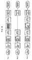
- Figure 14 illustrates the process for preparing a wafer for evaluating the quality of oxide film.
- the process of Run 1 is a process according to the present invention.
- Si wafer After treating Si wafer with HF, it is washed with ultra-pure water and the water on the wafer is removed with spin drier, after which wafer is oxidized by dipping it in a superultra-pure water having a temperature of 80°C for 30 minutes (this is one example of the present invention). Then, the water on the wafer is removed with spin drier and the wafer is oxidized in furnace.
- the process of Run 3 is different from that of Run 1 in that oxidation is carried out in an ultra-pure water instead of superultra-pure water, though the conditions of the oxidation are identical (dipping at 80°C for 30 minutes).
- the process of Run 2 corresponds to the existing process which lacks the step of oxidation in water.
- the condition of HF treatment is "dipping in 10% HF for 30 seconds”
- the condition of washing with ultra-pure water is "15 minutes with flowing water”
- the time of drying with spin drier is 4 minutes
- the conditions of oxidation in furnace are "at 850°C for 33 minutes", which are all identical throughout the processes.
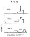
- Figure 15 illustrates the result of breakdown voltage performance test on the wafers having oxide films formed by Runs 1 to 3 of Figure 14. The measurement was carried out on approximately 300 points, and thickness of oxide film was 200 ⁇ . The result demonstrates that preparation of wafer according to Run 1 is best, because it produced no defective sample.
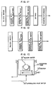
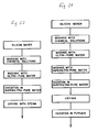
- Figure 17 is a flow diagram illustrating the washing of silicon wafer and formation of oxide film according to the present invention.
- a silicon wafer substrate is washed with chemical solutions in order to remove the surface pollutions and natural oxide film.
- the chemical solutions used above are washed away with an ultra-pure water, after which the wafer is oxidized with a fresh superultra-pure water in water.
- the wafer is dried by the method of spin drying, IPA vapor drying or steam drying and then oxidized in a furnace.
- the surface of silicon wafer keeps hydrophilic during the period from the washing step to the drying step and further to the oxidation step, so that its pollution can be prevented to a considerable extent as compared with the case of prior process where the wafer surface was hydrophobic. Since this process is accompanied by a phase change, the cost of water thus produced is necessarily high. In order to reduce the cost of process, there may be another process shown in Figure 21 where prior-art inexpensive ultra-pure water is used for removing the chemical solutions and the superultra-pure water is used in the subsequent steps of washing and oxidation in water.
- Figure 18 is another example of the process for washing silicon wafer and forming oxide film according to the present invention.
- the impurities on the wafer surface are removed with chemical solutions and the chemical solutions are washed with ultra-pure water, after which an oxide film necessary for production of semiconductor is formed in a superultra-pure water, so that oxidation furnace is unnecessary unlike the prior processes.
- the steps of washing and oxidation can be carried out simultaneously, owing to which transportation between steps is unnecessary and pollution is prevented. Further, the velocity of oxidation is not high, so that thickness of film can be controlled easily.
- FIG 19 illustrates one example of the in-water oxidation film-forming tank according to the present invention.
- Oxide tank 31' is composed of an insoluble material such as quarz glass, and superultra-pure water 34 is sent from the bottom of oxidation tank and made to overflow.
- Oxidation tank 31 is equipped with heater 33' for the sake of water temperature control, and silicon wafer 32' is completely dipped.
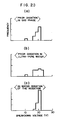
- the voltage-withstand performance of the oxide film having a thickness of about 200 ⁇ , prepared according to the process of Figure 17, is compared with that of a prior sample prepared without in-water oxidation and another prior sample prepared by in-water oxidation using prior-art ultra-pure water.
- the sample prepared by the process of the invention is comparable in the performance to the other samples prepared by prior-art methods. This demonstrates the high quality of the oxide film of the invention.
- Figure 22 illustrates one example which is a further advanced example of the system of the invention.
- the silicon wafer is washed with ultra-pure water and then washed and oxidized in superultra-pure water. Subsequently, it is dried by the use of a steam having passed hydrophobic porous membrane. According to this process, washing and oxidation can be carried out in one tank, so that external pollutions can be prevented. Further, owing to the drying process using steam, drying can be carried out without contamination by external impurities.
- Table 1 illustrates the water qualities of a superultra-pure water prepared by the process according to the invention and a prior-art ultra-pure water.
- the hydrophobic porous membrane used herein is a porous PTFE membrane having a pore size of 0.2 ⁇ m, and the boiling is carried out under ordinary pressure (at 100°C) Table 1 Water qualities of superultra-pure water and ultra-pure water Item Superultra-pure water Ultra-pure water Specific resistance (M ⁇ cm) 18 or above 18 or above TOC (ppb) 20 50 or below Fine particles (number/ml) 12 (0.1 ⁇ m or above) 50 (0.1 ⁇ m or above) Alive microorganisms (number/ml) Undetectable 0.25
- the formed oxide film contains no metallic components and has a high quality.
- Figure 23 is a diagram illustrating the construction of one example of the invention, wherein substrate 1'' is placed on heat transfer plate 2'' provided in container 3'', and said heat transfer plate 2'' is heated by heating element 5''.
- Container 3'' is provided with an exhaust hole 4 on its one terminal. The inner atmosphere of the container is kept clean.
- heat transfer plate 2'' heat is transferred to substrate 1 which is just after being washed with superultra-pure water and has adherent water drops, whereby the water is vaporized and dried up.
- the surface temperature of heating element 5'' is detected, and it is controlled so as to fulfil the above-mentioned temperature condition.
- a sucking apparatus or a throttling mechanism is connected to the exhaust hole 4'' in order to keep the inner pressure of container constant.
Landscapes
- Engineering & Computer Science (AREA)
- Water Supply & Treatment (AREA)
- Chemical & Material Sciences (AREA)
- Chemical Kinetics & Catalysis (AREA)
- Life Sciences & Earth Sciences (AREA)
- Hydrology & Water Resources (AREA)
- Environmental & Geological Engineering (AREA)
- Organic Chemistry (AREA)
- Heat Treatment Of Water, Waste Water Or Sewage (AREA)
- Vaporization, Distillation, Condensation, Sublimation, And Cold Traps (AREA)
- Physical Water Treatments (AREA)
- Cleaning Or Drying Semiconductors (AREA)
Claims (19)
- Verfahren zur Herstellung von superultrareinem Wasser aus Rohwasser in der Form von Industriewasser oder Umkehrosmosewasser oder dergleichen, das flüchtige und nicht flüchtige Komponenten enthält und vorbehandelt ist, um die Abscheidung von Kesselstein zu verhindern, wobei das Verfahren folgende Schritte aufweist:- Erhitzen und Sieden des Rohwassers in einer ersten Säule (2, 4, 21), um dadurch die flüchtigen Komponenten auszudampfen,- Abführen der verdampften flüchtigen Komponenten zusammen mit Wasserdampf aus der ersten Säule (2, 4, 21),- Überführen des von flüchtigen Komponenten freien Rohwassers zu einer zweiten Säule (1, 3, 5, 6; 22, 32, 42),- Erhitzen des von flüchtigen Komponenten freien Rohwassers in der zweiten Säule (1, 3, 5, 6; 22, 32, 42) derart, daß Wasserdampf erzeugt wird,- Kontaktieren des in der zweiten Säule (1, 3, 5, 6; 22, 32, 42) erzeugten Wasserdampfs mit einer hydrophoben, porösen, gasdurchlässigen und flüssigkeitsundurchlässigen Membran (101, 105, 31, 46), um den Wasserdampf durch die Membran (111, 105, 31, 46) hindurchtreten zu lassen und um die metallischen Komponenten, welche Nebel von winzigen, den Dampf begleitenden Tröpfchen enthalten, abzutrennen und- Kondensieren des Wasserdampfs zu superultrareinem Wasser, welches-- einen spezifischen Widerstand von 18 MΩ cm oder darüber,-- einen Gesamtgehalt an organischem Kohlenstoff von nicht mehr als 20 x 10⁻³ ppm,-- 12 oder weniger Feinteilchen pro ml mit einer Größe von 0,1 µm oder darüber und-- lebende Mikroorganismen in nicht feststellbarem Ausmaß aufweist.
- Verfahren nach Anspruch 1, bei welchem der Wasserdampf, der durch die Membran (101, 105, 31, 46) hindurchgegangen ist, in eine Atmosphäre aus gesättigtem Wasserdampf oder aus Inertgas eingeführt wird, in welcher der Wasserdampf kondensiert wird.
- Verfahren nach Anspruch 1 oder 2, bei welchem das Rohwasser unter einem reduzierten Druck in der ersten Säule (2, 4, 21) gehalten wird, während es siedet, um die flüchtigen Komponenten auszudampfen.
- Verfahren nach einem der Ansprüche 1 bis 3, bei welchem nur der Wasserdampf mit der hydrophoben, porösen, gasdurchlässigen und flüssigkeitsundurchlässigen Membran (101, 105, 31, 46) in der zweiten Säule (1, 3, 5, 6; 22, 32, 42) kontaktiert wird.
- Verfahren nach einem der vorhergehenden Ansprüche, bei welchem das Rohwasser, aus welchem die flüchtigen Komponenten in der ersten Säule (2, 4, 21) ausgedampft worden sind, in der zweiten Säule (1, 3, 5, 6; 22, 32, 42) in Wärmeaustausch mit dem Dampf erwärmt wird, der zusammen mit den verdampften flüchtigen Komponenten aus der ersten Säule (2, 4, 21) abgeführt wird.
- Verfahren nach einem der vorhergehenden Ansprüche, bei welchem die flüchtigen Komponenten aus dem Rohwasser in der ersten Säule (2, 4, 21) durch Flashverdampfung des Rohwassers entfernt werden.
- Vorrichtung zu Herstellung von superultrareinem Wasser, insbesondere nach einem der vorhergehenden Ansprüche- mit einer ersten Säule (2, 4, 21) für das Entfernen flüchtiger Komponenten, die-- mit Einrichtungen (110; 302, 303, 23) zum Erhitzen und Sieden des flüchtige und nicht flüchtige Komponenten enthaltenden Rohwassers,-- mit Einrichtungen (112, 203, 410, 24) zum Abführen der durch die Erhitzung gebildeten verdampften flüchtigen Komponenten und-- mit Einrichtungen (106, 114; 440, 26, 41) zum Überführen des Rohwassers, aus welchem die flüchtigen Komponenten ausgedampft sind, von der ersten Säule (2, 4, 21) zu- wenigstens einer zweiten Destillationssäule (1; 3, 5, 6; 22, 32, 42) ausgerüstet ist, die mit einer Wärmequelle (108, 202, 28) zum Erwärmen des überführten Rohwassers versehen ist, so daß Wasserdampf erzeugt wird,- mit einer hydrophoben, porösen, gasdurchlässigen und flüssigkeitsundurchlässigen Membran (101, 105, 31, 46), die jeder Destillationssäule (1; 3, 5, 6; 22, 32, 42) zugeordnet ist, wobei der in der zweiten Säule (1; 3, 5, 6; 22, 32, 42) erzeugte Wasserdampf mit der Membran (101, 105, 31, 46) kontaktiert wird,- mit Kühleinrichtungen (113; 7; 32; 43) zum Kondensieren des Wasserdampfs, der durch die Membran (101, 105, 31, 46) hindurchgegangen ist, zu superultrareinem Wasser, und- mit Abführeinrichtungen (104, 413, 402, 401, 35, 45) für das kondensierte superultrareine Wasser.
- Vorrichtung nach Anspruch 7, bei welcher die hydrophobe, poröse, gasdurchlässige und flüssigkeitsundurchlässige Membran (101, 105, 46) innerhalb der Destillationssäule (1, 3, 5, 42) angebracht ist.
- Vorrichtung nach Anspruch 8, bei welcher die Kühleinrichtung (113) zum Kondensieren des Wasserdampfs, der durch die Membran (101, 105, 46) hindurchgegangen ist, innerhalb der Destillationssäule (1, 3, 5, 42) angeordnet ist.
- Vorrichtung nach einem der Ansprüche 7 bis 9, bei welcher die Einrichtungen (203, 410, 24) zum Abführen der verdampften flüchtigen Komponenten, die durch das Erhitzen in der ersten Säule (2, 4, 21) zum Entfernen flüchtiger Komponenten mit Einrichtungen (202) für einen Wärmeaustausch in der Destillationssäule (3, 5, 22, 42) verbunden sind, um wenigstens teilweise als die Wärmequelle für die Erzeugung von Wasserdampf in der Destillationssäule (3, 5, 22, 42) zu wirken.
- Vorrichtung nach einem der Ansprüche 7 bis 10, bei welcher die Einrichtungen (302, 303) zum Erhitzen und Sieden des flüchtige und nicht flüchtige Komponenten enthaltenden Rohwassers ein Heizkörper (302) und eine Sprühdüse (303) für eine Flashverdampfung sind.
- Vorrichtung nach einem der Ansprüche 8 bis 11, bei welcher eine Gaszuführungseinrichtung vorgesehen ist, um die Atmosphäre zum Kondensieren des Wasserdampfs in der Destillationssäule (1, 3, 5, 6, 22, 32, 42) zu einer Atmosphäre aus gesättigtem Wasserdampf oder Inertgas zu machen.
- Vorrichtung nach einem der Ansprüche 7 bis 12, bei welcher die Säule (2, 4, 21) zum Entfernen flüchtiger Komponenten mit einer druckreduzierenden Einrichtung versehen ist.
- Verwendung von superultrareinem Wasser, das nach dem Verfahren nach einem der Ansprüche 1 bis 6 und/oder mit einer Vorrichtung nach einem der Ansprüche 7 bis 13 hergestellt wurde, zum Waschen von Halbleiter-ICs.
- Verwendung von superultrareinem Wasser, das nach dem Verfahren nach einem der Ansprüche 1 bis 6 und/oder mit einer Vorrichtung nach einem der Ansprüche 7 bis 13 hergestellt wurde, zum Waschen von medizinischen Werkzeugen.
- Verwendung von superultrareinem Wasser, das nach dem Verfahren nach einem der Ansprüche 1 bis 6 und/oder mit einer Vorrichtung nach einem der Ansprüche 7 bis 13 hergestellt wurde, zur Herstellung von Arzneimitteln.
- Verwendung von superultrareinem Wasser, das nach dem Verfahren nach einem der Ansprüche 1 bis 6 und/oder mit einer Vorrichtung nach einem der Ansprüche 7 bis 13 hergestellt wurde, zur Oxidierung der Siliziumoberfläche eines Halbleiterwafers durch Kontaktieren der Siliziumoberfläche mit dem superultrareinem Wasser.
- Verwendung nach Anspruch 17, bei welcher die Dicke des Oxydfilms durch Ändern der Temperatur des superultrareinen Wassers und/oder der Kontaktzeit mit dem superultrareinen Wasser gesteuert wird.
- Verwendung nach Anspruch 17 oder 18, bei welcher die mit dem superultrareinem Wasser kontaktierte Oberfläche durch Verdampfen des anhaftenden superultrareinen Wassers mit einer gesteuerten Verdampfungsgeschwindigkeit getrocknet wird.
Applications Claiming Priority (10)
| Application Number | Priority Date | Filing Date | Title |
|---|---|---|---|
| JP62068893A JPS63236333A (ja) | 1987-03-25 | 1987-03-25 | 基板の洗浄乾燥方法 |
| JP68893/87 | 1987-03-25 | ||
| JP139782/87 | 1987-06-05 | ||
| JP62139782A JPS63305917A (ja) | 1987-06-05 | 1987-06-05 | 超純水製造方法及びその製造装置 |
| JP201718/87 | 1987-08-14 | ||
| JP62201718A JPS6445130A (en) | 1987-08-14 | 1987-08-14 | Underwater oxidation of semiconductor wafer |
| JP209989/87 | 1987-08-24 | ||
| JP20998987A JPH0779994B2 (ja) | 1987-08-24 | 1987-08-24 | 超純水製造方法 |
| JP62233399A JPS6476726A (en) | 1987-09-17 | 1987-09-17 | Manufacture of semiconductor |
| JP233399/87 | 1987-09-17 |
Publications (3)
| Publication Number | Publication Date |
|---|---|
| EP0284052A2 EP0284052A2 (de) | 1988-09-28 |
| EP0284052A3 EP0284052A3 (en) | 1990-07-25 |
| EP0284052B1 true EP0284052B1 (de) | 1993-09-29 |
Family
ID=27524143
Family Applications (1)
| Application Number | Title | Priority Date | Filing Date |
|---|---|---|---|
| EP88104672A Expired - Lifetime EP0284052B1 (de) | 1987-03-25 | 1988-03-23 | Verfahren zur Erzeugung hochreinen Wassers und Verfahren zur Verwendung dieses Wassers |
Country Status (4)
| Country | Link |
|---|---|
| US (1) | US4879041A (de) |
| EP (1) | EP0284052B1 (de) |
| KR (1) | KR960003543B1 (de) |
| DE (1) | DE3884435T2 (de) |
Families Citing this family (78)
| Publication number | Priority date | Publication date | Assignee | Title |
|---|---|---|---|---|
| US5105556A (en) * | 1987-08-12 | 1992-04-21 | Hitachi, Ltd. | Vapor washing process and apparatus |
| JPH0630764B2 (ja) * | 1989-03-06 | 1994-04-27 | 森田化学工業株式会社 | 超純水ラインの滅菌方法 |
| PL161104B1 (pl) * | 1989-06-09 | 1993-05-31 | Sposób wzbogacania wody w skladniki wody ciezkiej PL | |
| PL161105B1 (pl) * | 1989-06-09 | 1993-05-31 | Sposób wzbogacania wody naturalnej w tlen-18 PL | |
| US5063609A (en) * | 1989-10-11 | 1991-11-05 | Applied Materials, Inc. | Steam generator |
| US4978550A (en) * | 1990-04-03 | 1990-12-18 | Eastman Kodak Company | Reverse osmosis water purification system for producing carbonated water |
| US5102550A (en) * | 1990-11-01 | 1992-04-07 | The United States Of America As Represented By The Secretary Of The Navy | Apparatus and process for desalination of seawater |
| US5242468A (en) * | 1991-03-19 | 1993-09-07 | Startec Ventures, Inc. | Manufacture of high precision electronic components with ultra-high purity liquids |
| JPH05136114A (ja) * | 1991-11-08 | 1993-06-01 | Tadahiro Omi | 超純水供給装置及び基体洗浄方法並びに超純水製造装置及び超純水製造方法 |
| KR960016302B1 (ko) * | 1992-05-15 | 1996-12-09 | 마쯔시다덴기산교 가부시기가이샤 | 순수(純水)의 제조장치 및 순수의 제조방법 |
| WO1994018127A1 (fr) * | 1993-02-03 | 1994-08-18 | Kurita Water Industries Ltd. | Procede de production d'eau pure |
| US5376281A (en) * | 1993-07-21 | 1994-12-27 | Safta; Eugen | Water purification system |
| US5525237A (en) * | 1993-12-23 | 1996-06-11 | United Technologies Corporation | Process for removing free and dissolved CO2 from aqueous solutions |
| US5518626A (en) * | 1993-12-23 | 1996-05-21 | United Technologies Corporation | Process employing thermally sterilizable aqueous polishing agents |
| CA2116089C (en) * | 1994-02-21 | 2004-05-04 | Fuelmaker Corporation | Method and apparatus for dewatering gas stream resulting in a clean water effluent |
| US5518624A (en) * | 1994-05-06 | 1996-05-21 | Illinois Water Treatment, Inc. | Ultra pure water filtration |
| AU684210B2 (en) * | 1994-08-19 | 1997-12-04 | Water Research Commission | A water purification device |
| JP2606156B2 (ja) * | 1994-10-14 | 1997-04-30 | 栗田工業株式会社 | 研磨剤粒子の回収方法 |
| JPH11506431A (ja) * | 1995-05-15 | 1999-06-08 | インテグレイテッド プロセス エクイプメイント コーポレイション(アイ ピー イー シー) | イソプロピルアルコールの無水化及び純粋化 |
| US5766479A (en) * | 1995-08-07 | 1998-06-16 | Zenon Environmental Inc. | Production of high purity water using reverse osmosis |
| US5695545A (en) * | 1996-05-10 | 1997-12-09 | Hoechst Celanese Corporation | Degassing liquids: apparatus and method |
| AU3137097A (en) | 1996-05-16 | 1997-12-05 | Lockheed Martin Energy Systems, Inc. | Low temperature material bonding technique |
| US8758720B2 (en) * | 1996-08-12 | 2014-06-24 | Debasish Mukhopadhyay | High purity water produced by reverse osmosis |
| US20020153319A1 (en) | 1997-08-12 | 2002-10-24 | Debasish Mukhopadhyay | Method and apparatus for high efficiency reverse osmosis operation |
| JP3171807B2 (ja) | 1997-01-24 | 2001-06-04 | 東京エレクトロン株式会社 | 洗浄装置及び洗浄方法 |
| AU7374098A (en) * | 1997-05-16 | 1998-12-08 | Pure Water, Inc. | Water distiller system for medical applications |
| US5997745A (en) * | 1998-04-08 | 1999-12-07 | Zenon Environmental Inc. | Method for producing high purity water using triple pass reverse osmosis (TPRO) |
| US6120689A (en) * | 1997-08-22 | 2000-09-19 | Zenon Environmental, Inc. | High purity water using triple pass reverse osmosis (TPRO) |
| FI103106B (fi) * | 1997-11-12 | 1999-04-30 | Steris Europe Inc | Menetelmä ja laite puhtaan veden tuottamiseksi |
| US6365051B1 (en) | 1999-10-12 | 2002-04-02 | Mansour S. Bader | Precipitation-membrane distillation hybrid system for the treatment of aqueous streams |
| US6663778B1 (en) | 1999-10-12 | 2003-12-16 | Mansour S. Bader | Process for the treatment of aqueous streams containing inorganics |
| US6652972B1 (en) | 1999-11-01 | 2003-11-25 | Schott Glass Technologies Inc. | Low temperature joining of phosphate glass |
| US7364625B2 (en) * | 2000-05-30 | 2008-04-29 | Fsi International, Inc. | Rinsing processes and equipment |
| US6733637B1 (en) * | 2000-06-02 | 2004-05-11 | Exxonmobil Chemical Patents Inc. | Process for producing ultra-high purity isopropanol |
| EP1296904A1 (de) | 2000-06-20 | 2003-04-02 | Schott Glass Technologies, Inc. | Glas-keramik verbundkörper |
| US6927176B2 (en) * | 2000-06-26 | 2005-08-09 | Applied Materials, Inc. | Cleaning method and solution for cleaning a wafer in a single wafer process |
| US6464880B1 (en) * | 2000-09-19 | 2002-10-15 | University Of Chicago | Microporous ionomeric materials and methods of preparation |
| US6882782B2 (en) * | 2000-11-01 | 2005-04-19 | Schott Glas | Photonic devices for optical and optoelectronic information processing |
| US6842998B2 (en) * | 2001-04-06 | 2005-01-18 | Akrion Llc | Membrane dryer |
| US7318894B2 (en) * | 2001-08-29 | 2008-01-15 | Graham John Gibson Juby | Method and system for treating wastewater |
| JP2003077993A (ja) * | 2001-08-30 | 2003-03-14 | Nec Yamagata Ltd | ウェーハ用ホルダ、及び、ウェーハの吸着解放方法 |
| AU2003243974A1 (en) * | 2002-06-25 | 2004-01-06 | Tokyo Electron Limited | Substrate processing device |
| JP4291034B2 (ja) * | 2003-04-25 | 2009-07-08 | 大日本スクリーン製造株式会社 | 洗浄装置および基板処理装置 |
| US20040238343A1 (en) * | 2003-05-28 | 2004-12-02 | Joseph Kuo | Membrane distillation method |
| US8722160B2 (en) * | 2003-10-31 | 2014-05-13 | Aeris Capital Sustainable Ip Ltd. | Inorganic/organic hybrid nanolaminate barrier film |
| US7198717B2 (en) * | 2004-08-26 | 2007-04-03 | Graham John Gibson Juby | Anoxic biological reduction system |
| US7399344B1 (en) * | 2005-01-28 | 2008-07-15 | Uop Llc | Hydrogen peroxide recovery with hydrophobic membrane |
| EP1924334A4 (de) | 2005-09-13 | 2009-11-11 | Rasirc | Verfahren zur herstellung einer hochreinen strömung |
| US8926731B2 (en) * | 2005-09-13 | 2015-01-06 | Rasirc | Methods and devices for producing high purity steam |
| US7892321B2 (en) * | 2006-02-01 | 2011-02-22 | Intelligent Energy, Inc. | Integrated heated prevaporation module |
| US7837877B2 (en) * | 2006-06-09 | 2010-11-23 | Air Products And Chemicals, Inc. | Process for separating components of a multi-component feed stream |
| EP1925355A1 (de) * | 2006-10-31 | 2008-05-28 | Nederlandse Organisatie voor toegepast- natuurwetenschappelijk onderzoek TNO | Membrandestillationsverfahren zur Reinigung einer Flüssigkeit |
| NZ586924A (en) * | 2008-01-18 | 2012-08-31 | Fresenius Med Care Hldg Inc | Carbon dioxide gas removal from a fluid circuit of a dialysis device with device having annular concentric housings |
| US9346021B2 (en) * | 2008-12-02 | 2016-05-24 | Membrane Distillation Desalination Ltd., Co. | Composite membranes for membrane distillation and related methods of manufacture |
| US8652332B2 (en) * | 2009-01-09 | 2014-02-18 | Massachusetts Institute Of Technology | Liquid filtration using pressure difference across a hydrophobic membrane |
| EP2445617A4 (de) * | 2009-06-23 | 2014-07-02 | Ceramatec Inc | Hochtemperatur-dampfselektive membran |
| CN102398895B (zh) * | 2010-09-16 | 2014-09-24 | 上海化学试剂研究所 | 一种超纯电子级化学试剂的生产方法 |
| CN102399140B (zh) * | 2010-09-17 | 2015-04-15 | 联仕(上海)电子化学材料有限公司 | 一种超纯电子级醋酸的生产方法 |
| NL2009613C2 (en) * | 2012-10-11 | 2014-04-15 | Aquaver B V | Membrane distillation system, method of starting such a system and use thereof. |
| GB2509721A (en) * | 2013-01-09 | 2014-07-16 | Univ Swansea | Membrane distillation process |
| US9358508B2 (en) * | 2013-04-25 | 2016-06-07 | Lockheed Martin Corporation | Dryer and water recovery/purification unit employing graphene oxide or perforated graphene monolayer membranes |
| US9200800B2 (en) * | 2014-01-17 | 2015-12-01 | General Electric Company | Method and system for steam generation and purification |
| KR101564759B1 (ko) * | 2014-02-04 | 2015-11-02 | 한국과학기술연구원 | 막 증류 수처리 용 분리막 |
| KR101656569B1 (ko) * | 2014-09-02 | 2016-09-23 | 한양대학교 에리카산학협력단 | 에너지 생산 장치 |
| EP3286140A4 (de) * | 2015-04-23 | 2019-04-17 | Aquatech International LLC | Verfahren und vorrichtung für fortgeschrittene vakuummembrandestillation |
| EP3195915A1 (de) * | 2016-01-20 | 2017-07-26 | Sulzer Chemtech AG | System zur reinigung eines organischen lösungsmittels und verfahren zur verwendung davon |
| US10239770B2 (en) * | 2016-04-29 | 2019-03-26 | Kookmin University Industry Academy Cooperation Foundation | Multi-stage submerged membrane distillation water treatment apparatus |
| WO2019049857A1 (ja) * | 2017-09-07 | 2019-03-14 | 旭化成株式会社 | 多孔質膜を用いたろ過方法 |
| WO2019126428A1 (en) * | 2017-12-20 | 2019-06-27 | Evoqua Water Technologies Llc | Hot water cart conditioning system and method |
| CN112292564A (zh) * | 2018-05-04 | 2021-01-29 | 唐纳森公司 | 用于从蒸汽中去除有机化合物的系统和方法 |
| CN112601593B (zh) | 2018-06-08 | 2022-10-28 | 伊弗科恩有限责任公司 | 多阶段膜蒸馏设备 |
| US12134075B2 (en) | 2018-06-08 | 2024-11-05 | Evcon Gmbh | Membrane distillation apparatus for producing water |
| CN112638511B (zh) | 2018-06-08 | 2023-01-10 | 伊弗科恩有限责任公司 | 具有非对称或间断液体通路的模块化流系统 |
| WO2019233607A1 (en) | 2018-06-08 | 2019-12-12 | Evcon Gmbh | Modular flow system with internal strut members |
| EP3801845B1 (de) | 2018-06-08 | 2024-10-30 | EvCon GmbH | Modulares strömungssystem mit verbesserter dampf- und/oder flüssigkeitskanalkonfiguration |
| US11649178B2 (en) | 2019-10-15 | 2023-05-16 | Donaldson Company, Inc. | Systems and methods for removing organic compounds from water used to generate steam |
| EP4490111A4 (de) * | 2021-03-11 | 2025-08-13 | Ellen Medical Devices Pty Ltd | System, verfahren und vorrichtung zur behandlung einer flüssigkeit |
| CN114804263A (zh) * | 2022-04-24 | 2022-07-29 | 扬州大学 | 一种利用电磁感应加热的自热膜蒸馏净水系统 |
Family Cites Families (7)
| Publication number | Priority date | Publication date | Assignee | Title |
|---|---|---|---|---|
| US2893926A (en) * | 1957-06-13 | 1959-07-07 | Bethlehem Steel Corp | Combined flash type distilling plant and back-pressure turbo-generator |
| GB988023A (en) * | 1962-03-09 | 1965-03-31 | Texas Instruments Inc | Method of providing protection for a pn junction formed in a silicon body |
| US3418214A (en) * | 1967-02-16 | 1968-12-24 | Westinghouse Electric Corp | Integral make-up deaerator for flash evaporator |
| DE1642833A1 (de) * | 1967-03-16 | 1971-04-29 | Yves Henderyckx | Verfahren und Vorrichtung zum Abtrennen eines oder mehrerer Bestandteile aus einer Loesung |
| JPS60166040A (ja) * | 1984-02-08 | 1985-08-29 | Hitachi Ltd | イオン交換樹脂の調整法 |
| US4725359A (en) * | 1985-02-25 | 1988-02-16 | Bend Research, Inc. | Potable water from internal combustion engines |
| DE3685205D1 (de) * | 1985-12-18 | 1992-06-11 | Hitachi Ltd | Destilliervorrichtung. |
-
1988
- 1988-03-23 DE DE88104672T patent/DE3884435T2/de not_active Expired - Fee Related
- 1988-03-23 EP EP88104672A patent/EP0284052B1/de not_active Expired - Lifetime
- 1988-03-24 US US07/172,583 patent/US4879041A/en not_active Expired - Lifetime
- 1988-03-24 KR KR1019880003177A patent/KR960003543B1/ko not_active Expired - Fee Related
Also Published As
| Publication number | Publication date |
|---|---|
| EP0284052A3 (en) | 1990-07-25 |
| DE3884435D1 (de) | 1993-11-04 |
| DE3884435T2 (de) | 1994-02-17 |
| KR890000135A (ko) | 1989-03-11 |
| KR960003543B1 (ko) | 1996-03-15 |
| US4879041A (en) | 1989-11-07 |
| EP0284052A2 (de) | 1988-09-28 |
Similar Documents
| Publication | Publication Date | Title |
|---|---|---|
| US4879041A (en) | Process for producing ultra-pure water and process for using said ultra-pure water | |
| US4984597A (en) | Apparatus for rinsing and drying surfaces | |
| US4788043A (en) | Process for washing semiconductor substrate with organic solvent | |
| US5105556A (en) | Vapor washing process and apparatus | |
| US4911761A (en) | Process and apparatus for drying surfaces | |
| US4953694A (en) | Distilling apparatus | |
| TWM526569U (zh) | 用於廢水處理之回收設備 | |
| KR20010012928A (ko) | 폐수 회수 처리 장치 | |
| KR20010104641A (ko) | 용제의 재생방법 및 장치 | |
| US6928750B2 (en) | Membrane dryer | |
| JP3922935B2 (ja) | 水処理システム | |
| EP0428784B1 (de) | Verfahren zum Trocknen von Oberflächen | |
| JPH04155924A (ja) | 蒸気乾燥装置 | |
| JPH0515486B2 (de) | ||
| EP1180497A1 (de) | Ionische Reinigungsvorrichtung | |
| JPH1116873A (ja) | 洗浄乾燥方法及び洗浄乾燥装置 | |
| KR100593600B1 (ko) | 폐수증발응축수 중의 오염물질 분리제거장치 | |
| US5138105A (en) | Process and apparatus for recovering a lower alcohol from a mixture thereof with water | |
| JPH05200230A (ja) | 半導体集積回路の洗浄方法及びその洗浄装置 | |
| JP2011146642A (ja) | 重水の貯蔵方法及び回収方法 | |
| JP2898080B2 (ja) | 脱気膜装置の運転方法 | |
| JPH04290229A (ja) | 半導体洗浄方法および超純水製造装置 | |
| JPH03187A (ja) | 無菌水の製造装置 | |
| KR20190140270A (ko) | 이소프로필알코올 함유 폐수로부터 이소프로필알코올의 농축 및 폐수처리를 위한 증기투과막 분리공정 | |
| JP2026078849A (ja) | ガス供給装置及びガス供給方法 |
Legal Events
| Date | Code | Title | Description |
|---|---|---|---|
| PUAI | Public reference made under article 153(3) epc to a published international application that has entered the european phase |
Free format text: ORIGINAL CODE: 0009012 |
|
| 17P | Request for examination filed |
Effective date: 19880323 |
|
| AK | Designated contracting states |
Kind code of ref document: A2 Designated state(s): DE GB |
|
| PUAL | Search report despatched |
Free format text: ORIGINAL CODE: 0009013 |
|
| AK | Designated contracting states |
Kind code of ref document: A3 Designated state(s): DE GB |
|
| 17Q | First examination report despatched |
Effective date: 19910711 |
|
| GRAA | (expected) grant |
Free format text: ORIGINAL CODE: 0009210 |
|
| AK | Designated contracting states |
Kind code of ref document: B1 Designated state(s): DE GB |
|
| REF | Corresponds to: |
Ref document number: 3884435 Country of ref document: DE Date of ref document: 19931104 |
|
| PLBE | No opposition filed within time limit |
Free format text: ORIGINAL CODE: 0009261 |
|
| STAA | Information on the status of an ep patent application or granted ep patent |
Free format text: STATUS: NO OPPOSITION FILED WITHIN TIME LIMIT |
|
| 26N | No opposition filed | ||
| REG | Reference to a national code |
Ref country code: GB Ref legal event code: IF02 |
|
| PGFP | Annual fee paid to national office [announced via postgrant information from national office to epo] |
Ref country code: GB Payment date: 20020301 Year of fee payment: 15 |
|
| PGFP | Annual fee paid to national office [announced via postgrant information from national office to epo] |
Ref country code: DE Payment date: 20020328 Year of fee payment: 15 |
|
| PG25 | Lapsed in a contracting state [announced via postgrant information from national office to epo] |
Ref country code: GB Free format text: LAPSE BECAUSE OF NON-PAYMENT OF DUE FEES Effective date: 20030323 |
|
| PG25 | Lapsed in a contracting state [announced via postgrant information from national office to epo] |
Ref country code: DE Free format text: LAPSE BECAUSE OF NON-PAYMENT OF DUE FEES Effective date: 20031001 |
|
| GBPC | Gb: european patent ceased through non-payment of renewal fee |
Effective date: 20030323 |