EP0284072A2 - Appareil d'entrée de coordonnées - Google Patents
Appareil d'entrée de coordonnées Download PDFInfo
- Publication number
- EP0284072A2 EP0284072A2 EP88104759A EP88104759A EP0284072A2 EP 0284072 A2 EP0284072 A2 EP 0284072A2 EP 88104759 A EP88104759 A EP 88104759A EP 88104759 A EP88104759 A EP 88104759A EP 0284072 A2 EP0284072 A2 EP 0284072A2
- Authority
- EP
- European Patent Office
- Prior art keywords
- vibration
- pen
- transmission plate
- vibration transmission
- coordinates
- Prior art date
- Legal status (The legal status is an assumption and is not a legal conclusion. Google has not performed a legal analysis and makes no representation as to the accuracy of the status listed.)
- Ceased
Links
Images






Classifications
-
- G—PHYSICS
- G06—COMPUTING OR CALCULATING; COUNTING
- G06F—ELECTRIC DIGITAL DATA PROCESSING
- G06F3/00—Input arrangements for transferring data to be processed into a form capable of being handled by the computer; Output arrangements for transferring data from processing unit to output unit, e.g. interface arrangements
- G06F3/01—Input arrangements or combined input and output arrangements for interaction between user and computer
- G06F3/03—Arrangements for converting the position or the displacement of a member into a coded form
- G06F3/041—Digitisers, e.g. for touch screens or touch pads, characterised by the transducing means
- G06F3/043—Digitisers, e.g. for touch screens or touch pads, characterised by the transducing means using propagating acoustic waves
- G06F3/0433—Digitisers, e.g. for touch screens or touch pads, characterised by the transducing means using propagating acoustic waves in which the acoustic waves are either generated by a movable member and propagated within a surface layer or propagated within a surface layer and captured by a movable member
-
- Y—GENERAL TAGGING OF NEW TECHNOLOGICAL DEVELOPMENTS; GENERAL TAGGING OF CROSS-SECTIONAL TECHNOLOGIES SPANNING OVER SEVERAL SECTIONS OF THE IPC; TECHNICAL SUBJECTS COVERED BY FORMER USPC CROSS-REFERENCE ART COLLECTIONS [XRACs] AND DIGESTS
- Y10—TECHNICAL SUBJECTS COVERED BY FORMER USPC
- Y10S—TECHNICAL SUBJECTS COVERED BY FORMER USPC CROSS-REFERENCE ART COLLECTIONS [XRACs] AND DIGESTS
- Y10S367/00—Communications, electrical: acoustic wave systems and devices
- Y10S367/907—Coordinate determination
Definitions
- the present invention relates to a coordinates input device, and more particularly to a coordinates input device which detects vibration input by a vibration pen by a plurality of sensors arranged on a vibration transmission plate to detect coordinates of the vibration pen on the vibration transmission plate.
- the coordinates detection of the tablet in such a system uses one of the following methods.
- the tablet may be made of transparent material such as acryl plate or glass plate. Accordingly, the input tablet may be overlaid on a liquid crystal display so that it may be used as if an operator writes a pattern on a paper. Thus, an information input/output device having a high operability is provided.
- the transmission of the vibration is impeded by a crack or obstacle on the vibration transmission plate of the tablet, and a detection precision is lowered.
- Fig. 1 shows a configuration of the coordinates input device in accordance with the present invention.
- coordinates are input by a vibration pen 3 on an input tablet which may be a vibration transmission plate 8, and an input image is displayed on a display 11 ⁇ which may be a CRT on which the input tablet is overlaid, in accordance with the input coordinates information.
- Numeral 8 denotes the vibration transmission plate which may be made of acrylic plate or glass plate and which transmits vibration from the vibration pen 3 to vibration sensors 6 arranged at three corners.
- transmission time of ultrasonic vibration transmitted from the vibration pen 3 to the vibration sensors 6 through the vibration transmission plate 8 is measured to detect the coordinates of the vibration pen 3 on the vibration transmission plate 8.
- the periphery of the transmission plate 8 is supported by an anti-reflection member 7 such as silicone rubber in order to prevent the vibration transmitted from the vibration pen 3 from being reflected at the periphery back to a center area.
- an anti-reflection member 7 such as silicone rubber
- the vibration transmission plate 8 is arranged on a dot-display device 11 ⁇ such as CRT or liquid crystal display so that dots are displayed along lines drawn by the vibration pen 3. Namely, dots are displayed at those positions on the display 11 ⁇ which correspond to the detected coordinates of the vibration pen 3.
- the image consisting of points or lines input by the vibration pen 3 is displayed to follow loci of the vibration pen as if it were drawn on a sheet.
- the vibration pen 3 which transmits the ultrasonic vibration to the vibration transmission plate 8 has a vibrator 4 made of a piezoelectric element.
- the ultrasonic vibration generated by the vibrator 4 is transmitted to the vibration transmission plate 8 through a horn 5 having a pointed end.
- Fig. 2 shows a structure of the vibration pen 3.
- the vibrator 4 in the vibration pen 3 is driven by a vibrator driver 2.
- a drive signal for the vibrator 4 is supplied from the operation controller of Fig. 1 as a low level pulse signal. It is amplified by the vibrator driver 2 which can drive at a low impedance and has a predetermined gain, and the amplified signal is applied to the vibrator 4.
- the electrical drive signal is converted to a mechanical ultrasonic vibration by the virbator 4, and it is transmitted to the vibration plate 8 through the horn 5.
- the vibration frequency of the vibrator 4 is selected such that a plane wave can be generated in the vibration transmission plate 8 such as acrylic plate or glass plate.
- a vibration mode is selected such that the vibrator 4 principally vibrates vertically in Fig. 2 to the vibration transmission plate 8.
- the vibration frequency of the vibrator 4 may be set to a resonance frequency of the vibrator 4 to attain vibration transformation at a high efficiency.
- the elastic wave transmitted to the vibration transmission plate 8 in this manner is a plane wave which is less affected by the crack or obstacle on the surface of the vibration transmission plate 8 than a surface wave.
- the vibration sensors 6 arranged at the corners of the vibration transmission plate 8 are mechanical-electrical transducers such as piezoelectric elements.
- the output signals from the three vibration sensors 6 are applied to the waveform detector 9 where they are converted to signal forms which can be processed by the operation controller 1, which measures the vibration transmission time to detect the coordinates of the vibration pen 3 on the vibration transmission plate 8.
- the detected coordinates information of the vibration pen 3 is processed by the operation controller 1 in accordance with the output scheme of the display 11 ⁇ .
- the operation controller 1 controls the output operation of the display 11 ⁇ through a display driver 10 in accordance with the input coordinates information.
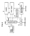
- Fig. 3 shows a configuration of the operation controller 1 of Fig. 1. It primarily shows a drive circuit for the vibration pen 3 and a vibration detection circuit by the vibration sensors 6.
- a microcomputer 11 has an internal counter, a ROM and a RAM.
- a drive signal generation 12 generates a drive pulse at a predetermined frequency for the vibrator driver 2 of Fig. 1. It is started by the microcomputer 11 in synchronism with the coordinates operation circuit.
- a count of a counter 13 is latched in a latch 14 by the microcomputer 11.
- the waveform detector 9 produces, based on the output of the vibration sensor 6, timing information of the detection signal for measuring the vibration transmission time for the coordinates detection, and signal level information for the pen pressure detection.
- the timing and level information are applied to input ports 15 and discrimination 16, respectively.
- the timing signal supplied from the waveform detector 9 is applied to the input port 15, compared with the count of the latch 14 by the discriminator 16, and the result is informed to the microcomputer 11.
- the vibration transmission time is expressed by the latched data of the counter 13, and the coordinates are calculated based on the vibration transmission time.
- the output operation of the display 11 ⁇ is controlled through an input/output port 17.
- Fig. 4 shows waveforms applied to the waveform detector 9 of Fig. 1 and illustrates measurement of the vibration transmission time.
- Numeral 41 denotes a drive signal pulse applied to the vibration pen 3.
- the ultrasonic vibration transmitted to the vibration transmission plate 8 from the vibration pen 3 driven by the pulse 41 propagates through the vibration transmission plate 8 and is detected by the vibration sensors 6.
- the vibration propagate through the vibration transmission plate 8 in a time tg representing a distance to the vibration sensor 6 and it reaches the vibration sensor 6.
- Numeral 42 denotes a signal waveform detected by the vibration sensor 6.
- the plane wave used in the present embodiment is a dispersive wave. Accordingly, a relationship between an envelope 421 and a phase 422 of the detected waveform relative to a propagation distance in the vibration transmission plate 8 changes with the transmission distance during the transmission of the vibration.
- the envelope has a group velocity Vg and a phase velocity Vp.
- the distance between the vibration pen 3 and the vibration sensor 6 is detected based on a difference between the group velocity and the phase velocity.
- the envelope 421 is considered first. It has the velocity Vg.
- Vg the distance between the vibration pen 3 and the vibration sensor 6
- d Vg ⁇ tg (1)
- tg is the vibration transmission time.
- the formula (1) relates to one of the vibration sensors 6.
- the distances between the vibration pen 3 and two other sensors 6 are given by the same formula.
- d n ⁇ ⁇ p + Vp ⁇ tp (2)
- tp is a time of a particular detection point on the phase waveform 422 of Fig. 4, for example, from the application of vibration to a zero-crossing point after the peak
- ⁇ p is a wavelength of the elastic wave
- n is an integer.
- the n thus determined is substituted in the formula (2) so that the distance between the vibration pen 3 and the vibration sensor 6 can be precisely measured.
- the vibration transmission times tg and tp shown in Fig. 4 are measured by the waveform detector 9 of Fig. 1.
- the waveform detector 9 is configured as shown in Fig. 5.
- the waveform detector of Fig. 5 also processes the level information of the output waveform of the vibration sensor 6 to detect the pen pressure.
- the output signal of the vibration sensor 6 is amplified to a predetermined level by a pre-amplifier 51.
- the amplified signal is supplied to an envelope detector 52 which extracts only an envelope of the detected signal.
- a timing of a peak of the extracted envelope is detected by an envelope peak detector 53.
- the peak detection signal is applied to a signal detector 54 which may be a monostable multivibrator and produces an envelope delay time detection signal Tg, which is supplied to the operation controller 1.
- a phase time detection signal Tp is produced by a comparator detector 58 based on the signal Tg and an original signal delayed by a delay time adjuster 57, and it is supplied to the operation controller 1.
- the circuit shown above is for one of the vibration sensors 6. The same circuit is provided for each of the rest. Where there are h sensors, the h envelope delay time detection signals Tg1-Tgh and the h phase delay time detection signals Tp1-Tph are supplied to the operation controller 1.
- the operation controller of Fig. 3 receives the signals Tg1-Tgh and Tp1-Tph from the input port 15 and latches the count of the counter 13 at the timing of those signals. Since the counter 13 is started in synchronism with the drive of the vibration pen as described above, the latch 14 latches data which represent both the delay times of the envelope and the phase.
- the operation controller 1 determines the coordinates (x, y) of the position p of the vibration pen 3 based on the distances d1-d3 in accordance with the theorem of three squares (Pythagoream theorem).
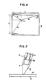
- a fine uneven surface is provided on the vibration transmission plate 8, as shown in Fig. 7.
- Numeral 71 denotes a bottom of a body of the vibration pen 3.
- the horn 5 is coupled to the end of the bottom 71 by a threaded portion 76.
- the vibration transmission plate 8 has the fine uneven surface to roughen the surface.
- the roughness is no less than #2000 of the mesh number.
- the transparency of the vibration transmission plate 8 is not reduced and the visibility of the underlying display is not lowered.
- the external light is diffusedly reflected by the surface roughness so that the visibility of the display is enhanced.
- the writing touch of the vibration pen 3 is also enhanced.
- the roughening may be effected not only on the front surface of the vibration transmission plate 8 but also on the back surface of the vibration transmission plate 8 to control the transparency of the vibration transmission plate 8 and the scattering of the external light and display light.
- the vibration detection characteristic is also improved by roughening the surface of the vibration transmission plate 8.
- Figs. 8 and 9 show vibration detection waveforms produced by the vibration sensor 6 located at the corner of the vibration transmission plate 8, without and with the roughening, respectively.
- the surface wave input to the vibration transmission plate 8 by the inclination of the vibration pen 3 is combined with the transmitted vibration so that a peak Wh appears.
- the peak by the surface wave component may be misdetected by the peak detection and an error is caused in the vibration transmission time or the coordinates detection precision.
- a resin layer 75 is provided on the surface of the vibration transmission plate 8, as shown in Fig. 10, numeral 71 denotes a bottom of the body of the vibration pen 3, and the horn 5 is coupled to the end thereof by a threaded portion 76.
- a resin layer 75 is coated on the surface of the vibration transmission plate 8.
- the resin layer 75 is made of appropriate material to attain a desired attenuation for the surface wave.
- the material and thickness of the resin layer 75 By properly selecting the material and thickness of the resin layer 75, it is possible to prevent the transparency of the vibration transmission plate 8 from being lowered and the visibility of the underlying display from being lowered. By the provision of the resin layer 75, the external light may be diffusedly reflected to improve the visibility of the display. The writing touch of the vibration pen 3 is also enhanced.
- the resin layer 75 may be coated not only on the front surface of the vibration transmission plate 8 but also on the back surface thereof to control the transparency of the vibration transmission plate 8 or the scattering of the external light or display light.
- the vibration detection characteristic may be enhanced.
- Figs. 11 and 12 show the vibration detection waveforms produced by the vibration sensor 6 located at the corner of the vibration transmission plate 8 without and with the resin layer 75, respectively.
- the surface wave input to the vibration transmission plate 8 by the inclination of the vibration pen 3 is combined with the transmitted vibration so that a peak Wh is produced.
- the peak of the surface wave component is misdetected by the peak Wh and error is created in the vibration transmission time and the coordinate detection precision.
- a coordinates input device comprises vibration means for generating vibration, a pen having an end to which the vibration generated by said vibration means is transmitted, and a vibration transmission plate having a roughened surface or resin coating on a pen abutment surface thereof, for transmitting the vibration.
Landscapes
- Engineering & Computer Science (AREA)
- Physics & Mathematics (AREA)
- General Engineering & Computer Science (AREA)
- Theoretical Computer Science (AREA)
- Acoustics & Sound (AREA)
- Human Computer Interaction (AREA)
- General Physics & Mathematics (AREA)
- Position Input By Displaying (AREA)
Applications Claiming Priority (4)
| Application Number | Priority Date | Filing Date | Title |
|---|---|---|---|
| JP62071400A JPS63239518A (ja) | 1987-03-27 | 1987-03-27 | 座標入力装置 |
| JP71400/87 | 1987-03-27 | ||
| JP77547/87 | 1987-04-01 | ||
| JP62077547A JPS63245711A (ja) | 1987-04-01 | 1987-04-01 | 座標入力装置 |
Publications (2)
| Publication Number | Publication Date |
|---|---|
| EP0284072A2 true EP0284072A2 (fr) | 1988-09-28 |
| EP0284072A3 EP0284072A3 (fr) | 1990-03-28 |
Family
ID=26412500
Family Applications (1)
| Application Number | Title | Priority Date | Filing Date |
|---|---|---|---|
| EP88104759A Ceased EP0284072A3 (fr) | 1987-03-27 | 1988-03-24 | Appareil d'entrée de coordonnées |
Country Status (2)
| Country | Link |
|---|---|
| US (1) | US4853496A (fr) |
| EP (1) | EP0284072A3 (fr) |
Cited By (2)
| Publication number | Priority date | Publication date | Assignee | Title |
|---|---|---|---|---|
| EP0364983A3 (en) * | 1988-10-20 | 1990-12-12 | Canon Kabushiki Kaisha | Coordinate input apparatus |
| EP0582283A1 (fr) * | 1992-08-05 | 1994-02-09 | Canon Kabushiki Kaisha | Tableau de transmission de vibrations pour l'entrée de coordonnées |
Families Citing this family (7)
| Publication number | Priority date | Publication date | Assignee | Title |
|---|---|---|---|---|
| US5097415A (en) * | 1987-03-24 | 1992-03-17 | Canon Kabushiki Kaisha | Coordinates input apparatus |
| JPH0746301B2 (ja) * | 1987-10-28 | 1995-05-17 | キヤノン株式会社 | 座標入力装置 |
| US5253187A (en) * | 1988-11-11 | 1993-10-12 | Canon Kabushiki Kaisha | Coordinate input apparatus |
| EP0421025B1 (fr) * | 1989-10-02 | 1999-05-06 | Koninklijke Philips Electronics N.V. | Système de traitement des données avec une surface tactile et une tablette à numériser, les deux intégrées dans un dispositif d'entrée |
| EP0436173B1 (fr) * | 1989-12-25 | 1997-09-10 | Canon Kabushiki Kaisha | Crayon d'entrée de données vibrant pour dispositif d'entrée de coordonnées |
| US5379269A (en) * | 1993-01-13 | 1995-01-03 | Science Accessories Corp. | Position determining apparatus |
| US5691959A (en) * | 1994-04-06 | 1997-11-25 | Fujitsu, Ltd. | Stylus position digitizer using acoustic waves |
Family Cites Families (2)
| Publication number | Priority date | Publication date | Assignee | Title |
|---|---|---|---|---|
| GB2042726A (en) * | 1979-03-07 | 1980-09-24 | Bransbury R | Pattern Logging Device |
| EP0169538B1 (fr) * | 1984-07-25 | 1991-05-29 | Hitachi, Ltd. | Appareil du type tablette pour l'entrée de coordonnées utilisant des ondes élastiques |
-
1988
- 1988-03-22 US US07/171,747 patent/US4853496A/en not_active Expired - Lifetime
- 1988-03-24 EP EP88104759A patent/EP0284072A3/fr not_active Ceased
Cited By (2)
| Publication number | Priority date | Publication date | Assignee | Title |
|---|---|---|---|---|
| EP0364983A3 (en) * | 1988-10-20 | 1990-12-12 | Canon Kabushiki Kaisha | Coordinate input apparatus |
| EP0582283A1 (fr) * | 1992-08-05 | 1994-02-09 | Canon Kabushiki Kaisha | Tableau de transmission de vibrations pour l'entrée de coordonnées |
Also Published As
| Publication number | Publication date |
|---|---|
| US4853496A (en) | 1989-08-01 |
| EP0284072A3 (fr) | 1990-03-28 |
Similar Documents
| Publication | Publication Date | Title |
|---|---|---|
| EP0526879B1 (fr) | Appareil d'entrée de coordonnées | |
| JP3007933B2 (ja) | 超音波座標入力装置 | |
| EP0296569B1 (fr) | Appareil pour l'entree de coordonnées | |
| US5097415A (en) | Coordinates input apparatus | |
| JPH0746301B2 (ja) | 座標入力装置 | |
| US4897510A (en) | Coordinate inputting device including an electrode to reduce noise components | |
| US4853496A (en) | Acoustic coordinate input device using a roughened surface to attenuate the surface wave component | |
| EP0284048B1 (fr) | Appareil pour l'entrée de coordonnées | |
| EP0367282B1 (fr) | Appareil pour l'éntrée de coordonnées | |
| JPH0618029B2 (ja) | 画像処理装置 | |
| JPS63245711A (ja) | 座標入力装置 | |
| JPH01112418A (ja) | 振動入力ペン | |
| JP2502648B2 (ja) | 座標入力装置 | |
| JPS63239518A (ja) | 座標入力装置 | |
| JPH02143316A (ja) | 座標入力装置 | |
| JP2654396B2 (ja) | 座標入力装置 | |
| JP2654397B2 (ja) | 座標入力装置 | |
| JPS63136127A (ja) | 座標入力装置 | |
| JPH0562773B2 (fr) | ||
| JPH0562772B2 (fr) | ||
| JPH0776901B2 (ja) | 座標入力装置 | |
| JPS63136126A (ja) | 座標入力装置 | |
| JPH0648456B2 (ja) | 座標入力装置 | |
| JPH02130617A (ja) | 座標入力装置 | |
| JPH01130216A (ja) | 座標入力装置 |
Legal Events
| Date | Code | Title | Description |
|---|---|---|---|
| PUAI | Public reference made under article 153(3) epc to a published international application that has entered the european phase |
Free format text: ORIGINAL CODE: 0009012 |
|
| AK | Designated contracting states |
Kind code of ref document: A2 Designated state(s): DE FR GB IT NL |
|
| PUAL | Search report despatched |
Free format text: ORIGINAL CODE: 0009013 |
|
| AK | Designated contracting states |
Kind code of ref document: A3 Designated state(s): DE FR GB IT NL |
|
| 17P | Request for examination filed |
Effective date: 19900810 |
|
| 17Q | First examination report despatched |
Effective date: 19920120 |
|
| STAA | Information on the status of an ep patent application or granted ep patent |
Free format text: STATUS: THE APPLICATION HAS BEEN REFUSED |
|
| 18R | Application refused |
Effective date: 19931030 |