EP0284083A2 - Scie circulaire à froid à lame de scie fixée sous une table - Google Patents
Scie circulaire à froid à lame de scie fixée sous une table Download PDFInfo
- Publication number
- EP0284083A2 EP0284083A2 EP88104803A EP88104803A EP0284083A2 EP 0284083 A2 EP0284083 A2 EP 0284083A2 EP 88104803 A EP88104803 A EP 88104803A EP 88104803 A EP88104803 A EP 88104803A EP 0284083 A2 EP0284083 A2 EP 0284083A2
- Authority
- EP
- European Patent Office
- Prior art keywords
- circular saw
- saw according
- table top
- bearing part
- hydraulic cylinder
- Prior art date
- Legal status (The legal status is an assumption and is not a legal conclusion. Google has not performed a legal analysis and makes no representation as to the accuracy of the status listed.)
- Withdrawn
Links
Images



Classifications
-
- B—PERFORMING OPERATIONS; TRANSPORTING
- B23—MACHINE TOOLS; METAL-WORKING NOT OTHERWISE PROVIDED FOR
- B23Q—DETAILS, COMPONENTS, OR ACCESSORIES FOR MACHINE TOOLS, e.g. ARRANGEMENTS FOR COPYING OR CONTROLLING; MACHINE TOOLS IN GENERAL CHARACTERISED BY THE CONSTRUCTION OF PARTICULAR DETAILS OR COMPONENTS; COMBINATIONS OR ASSOCIATIONS OF METAL-WORKING MACHINES, NOT DIRECTED TO A PARTICULAR RESULT
- B23Q1/00—Members which are comprised in the general build-up of a form of machine, particularly relatively large fixed members
- B23Q1/25—Movable or adjustable work or tool supports
- B23Q1/26—Movable or adjustable work or tool supports characterised by constructional features relating to the co-operation of relatively movable members; Means for preventing relative movement of such members
- B23Q1/28—Means for securing sliding members in any desired position
-
- B—PERFORMING OPERATIONS; TRANSPORTING
- B23—MACHINE TOOLS; METAL-WORKING NOT OTHERWISE PROVIDED FOR
- B23D—PLANING; SLOTTING; SHEARING; BROACHING; SAWING; FILING; SCRAPING; LIKE OPERATIONS FOR WORKING METAL BY REMOVING MATERIAL, NOT OTHERWISE PROVIDED FOR
- B23D45/00—Sawing machines or sawing devices with circular saw blades or with friction saw discs
- B23D45/06—Sawing machines or sawing devices with circular saw blades or with friction saw discs with a circular saw blade arranged underneath a stationary work-table
- B23D45/065—Sawing machines or sawing devices with circular saw blades or with friction saw discs with a circular saw blade arranged underneath a stationary work-table with the saw blade carried by a pivoted lever
- B23D45/066—Sawing machines or sawing devices with circular saw blades or with friction saw discs with a circular saw blade arranged underneath a stationary work-table with the saw blade carried by a pivoted lever the pivoted lever being mounted on a carriage
-
- B—PERFORMING OPERATIONS; TRANSPORTING
- B27—WORKING OR PRESERVING WOOD OR SIMILAR MATERIAL; NAILING OR STAPLING MACHINES IN GENERAL
- B27G—ACCESSORY MACHINES OR APPARATUS FOR WORKING WOOD OR SIMILAR MATERIALS; TOOLS FOR WORKING WOOD OR SIMILAR MATERIALS; SAFETY DEVICES FOR WOOD WORKING MACHINES OR TOOLS
- B27G5/00—Machines or devices for working mitre joints with even abutting ends
- B27G5/02—Machines or devices for working mitre joints with even abutting ends for sawing mitre joints; Mitre boxes
- B27G5/023—Machines or devices for working mitre joints with even abutting ends for sawing mitre joints; Mitre boxes the mitre angle being adjusted by positioning a workpiece relative to a fixed saw
Definitions
- Cold circular saws are used for burr-free exact sawing of steel profiles of various qualities, as well as most non-ferrous metals.
- a method for sawing e.g. B. of round and square tubes as particularly favorable for bevel cuts.
- These so-called under-table saws work vertically out of the table from below. This means that the saw blade is only visible when sawing.
- Machines that work in this way have been known for over 30 years.
- a disadvantage of the known machines is that the saw blade always comes out at the same point on the table. If, for example, a rectangular tube with a width of 240 mm is sawn to 90 °, the center of the saw blade should come out of the table 120 mm in front of the reference line.
- the object of the invention is to design an under-table cold circular saw so that the forces occurring are safely absorbed.
- pivot axis is mounted at right angles to it horizontally displaceable and can be clamped against displacement by a clamping device.
- the pivot axis is carried by a bearing part which is guided horizontally displaceably below the table top, since the clamping forces can then be taken over directly from the table top.
- the bearing part is guided horizontally displaceably with an upper plate on the underside of the table top.
- the bearing part can be clamped against the table top or against a part fastened to the machine base by a part, in particular a pull rod, spindle, eccentric or toothed rack.
- the pull rod can penetrate the table top and an elongated hole in the upper plate of the bearing part.
- Sufficiently high forces with simple and precise control are achieved when the part, in particular the tie rod a hydraulic cylinder piston unit can be actuated.
- a strengthening of the forces is achieved when a two-armed lever with its inner articulation point is attached to the pull rod and the hydraulic cylinder / piston unit is attached to one end of the lever.
- a part can be attached to the other end of the lever, which is connected to the device, in particular the hydraulic cylinder-piston unit, by means of which the workpieces can be clamped, so that the clamping of the workpieces automatically ensures that there is always sufficient force to hold the Swivel axis is given.
- the device is particularly easy to handle when the pivot axis, in particular the bearing part, can be adjusted by an adjusting member such as a spindle or a hydraulic cylinder piston unit. It is also proposed for a secure position of the bearing part in the clamped state that a plate is attached to the bottom of the tie rod, which rests on the underside of the plate of the bearing part with elevations, in particular grooves.
- the bearing part is preferably supported by guide parts.
- a miter stop is pivotally mounted on the top of the table top and can be clamped in place by a hydraulic cylinder / piston unit.
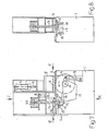
- the under-table cold circular saw has a lower part 1 which carries on its upper side a horizontal table top 2 on which the workpieces, in particular profiles for sawing, are moved and held.
- a hydraulic cylinder-piston unit 3 is provided, the vertical piston rod 4 of which clamps the workpieces 6 against the table top 2 with a lower part 5.
- a miter stop 7 is also pivotably mounted on the table top 2 and can be clamped by a second hydraulic cylinder piston unit 8.
- the circular saw blade 9 the horizontal axis 10 of which is mounted on a swivel arm 11 which carries a gear for the circular saw blade.
- the front end of the swivel arm 11 is actuated by a third hydraulic cylinder-piston unit 12 and the rear end is supported on a horizontal swivel axis 13 which is supported by a bearing part 14.
- the bearing part 14 has a horizontal plate 15 on its upper side, which rests on the underside of the table plate 2 so as to be displaceable transversely to the axis 13.
- a pull rod 17 In the plate 15 there is an elongated hole 16 through which a pull rod 17 is guided which carries a plate 18 on its underside in order to clamp the plate 15 against the table top 2 with this plate 18. Slipping of the plate 18 relative to the plate 15 is prevented by the fact that the plate 18 has grooves.
- the plate 15 is supported in guides, not shown, and is moved by an adjusting member 20, which can be a spindle or another hydraulic cylinder / piston unit.
- the upper end of the pull rod 17 is fixed to the inner articulation point 21 of a two-armed lever 22, one end of which is fixed to a further hydraulic cylinder piston unit 23 and the opposite free end lies with its underside on a bearing 24 which, in particular, connects to the hydraulic cylinder piston unit 3 with its cylinder, is connected so that actuation of the unit 3 leads to the piston rod 4 being pushed down and the bearing 24 being pushed up.
- the pull rod 17 can alternatively be actuated by a wide variety of devices.
- FIG. 7 shows a hydraulic cylinder / piston unit 25 which is attached directly to the pull rod 17 at the top.
- a rack or a spindle with a nut can be used instead of the tie rod.
Landscapes
- Engineering & Computer Science (AREA)
- Mechanical Engineering (AREA)
- Life Sciences & Earth Sciences (AREA)
- Wood Science & Technology (AREA)
- Forests & Forestry (AREA)
- Sawing (AREA)
Applications Claiming Priority (2)
| Application Number | Priority Date | Filing Date | Title |
|---|---|---|---|
| DE3710124 | 1987-03-27 | ||
| DE19873710124 DE3710124A1 (de) | 1987-03-27 | 1987-03-27 | Unter-tisch-kaltkreissaege |
Publications (2)
| Publication Number | Publication Date |
|---|---|
| EP0284083A2 true EP0284083A2 (fr) | 1988-09-28 |
| EP0284083A3 EP0284083A3 (fr) | 1990-02-07 |
Family
ID=6324125
Family Applications (1)
| Application Number | Title | Priority Date | Filing Date |
|---|---|---|---|
| EP88104803A Withdrawn EP0284083A3 (fr) | 1987-03-27 | 1988-03-25 | Scie circulaire à froid à lame de scie fixée sous une table |
Country Status (2)
| Country | Link |
|---|---|
| EP (1) | EP0284083A3 (fr) |
| DE (1) | DE3710124A1 (fr) |
Cited By (2)
| Publication number | Priority date | Publication date | Assignee | Title |
|---|---|---|---|---|
| EP0299227A3 (en) * | 1987-07-14 | 1989-11-02 | Dieter Kaltenbach | Cold circular saw with a saw blade upwardly movable through a supporting plate from underneath the supporting table |
| CN112276222A (zh) * | 2020-10-31 | 2021-01-29 | 株洲精工硬质合金有限公司 | 一种超硬材料生产加工用切割装置 |
Family Cites Families (4)
| Publication number | Priority date | Publication date | Assignee | Title |
|---|---|---|---|---|
| CH211526A (fr) * | 1939-06-30 | 1940-09-30 | Genevoise Instr Physique | Machine-outil. |
| US2540586A (en) * | 1947-09-24 | 1951-02-06 | Monarch Machine Tool Co | Tailstock carriage and clamping means |
| US2954062A (en) * | 1959-04-09 | 1960-09-27 | Leitchmer Edward | Adjustable gauges for a saw table |
| DE2915288C2 (de) * | 1979-04-14 | 1984-09-20 | Dieter 7850 Lörrach Kaltenbach | Kaltkreissäge mit einem schwenkbaren Sägeblattarm |
-
1987
- 1987-03-27 DE DE19873710124 patent/DE3710124A1/de not_active Withdrawn
-
1988
- 1988-03-25 EP EP88104803A patent/EP0284083A3/fr not_active Withdrawn
Cited By (2)
| Publication number | Priority date | Publication date | Assignee | Title |
|---|---|---|---|---|
| EP0299227A3 (en) * | 1987-07-14 | 1989-11-02 | Dieter Kaltenbach | Cold circular saw with a saw blade upwardly movable through a supporting plate from underneath the supporting table |
| CN112276222A (zh) * | 2020-10-31 | 2021-01-29 | 株洲精工硬质合金有限公司 | 一种超硬材料生产加工用切割装置 |
Also Published As
| Publication number | Publication date |
|---|---|
| DE3710124A1 (de) | 1988-10-06 |
| EP0284083A3 (fr) | 1990-02-07 |
Similar Documents
| Publication | Publication Date | Title |
|---|---|---|
| EP2251126B1 (fr) | Coulisseau transversal doté de plaques de butée déplaçables et motorisées pour scies circulaires à banc | |
| EP1517763B1 (fr) | Scie a ruban a metaux avec cadre de scie suspendu | |
| DE3246804C1 (de) | Trennvorrichtung | |
| DE3514169A1 (de) | Saegemaschine | |
| DE2127525C3 (de) | Zusatzeinrichtung für Drehautomaten zum spanlosen Ablängen von in der umlaufenden Werkstückspindel eingespannten Rohren oder dgl | |
| DE4225596A1 (de) | Spannvorrichtung | |
| DE2827776A1 (de) | Maschine zum kaltsaegen langgestreckter werkstuecke | |
| DE3203447A1 (de) | Keilschnittsaege | |
| DE3710124A1 (de) | Unter-tisch-kaltkreissaege | |
| DE1552612C3 (de) | Schneidemaschine für Stabmateria] | |
| DE3422101C2 (fr) | ||
| EP0674962A1 (fr) | Dispositif pour la coupe en longueur de profilés creux | |
| DE3347920A1 (de) | Saegeeinrichtung | |
| DE3544058C2 (de) | Sägeeinrichtung zum Zuschneiden von Profilleisten o.dgl. | |
| DE29907474U1 (de) | Sägevorrichtung | |
| DE3703874A1 (de) | Klinkschnittsaege | |
| DE102005062437B4 (de) | Blechschere zum Schneiden einer Blechtafel, Blechstreifen oder dergleichen | |
| DE19917535A1 (de) | Parallelanschlagsvorrichtung für eine Formatsägemaschine | |
| DE3432672C2 (fr) | ||
| DE2925401C2 (de) | Stichsäge mit Motorantrieb | |
| DE4128072A1 (de) | Saege | |
| DE4224052C2 (de) | Anschlagwinkel für Handarbeitsmaschine | |
| DE1502722C (de) | Bandsägemaschine | |
| DE29912713U1 (de) | Vorrichtung zum Abtrennen von Schweißgutüberständen | |
| DE7702782U1 (de) | Säge für Steinwerkstücke |
Legal Events
| Date | Code | Title | Description |
|---|---|---|---|
| PUAI | Public reference made under article 153(3) epc to a published international application that has entered the european phase |
Free format text: ORIGINAL CODE: 0009012 |
|
| AK | Designated contracting states |
Kind code of ref document: A2 Designated state(s): DE FR GB IT |
|
| PUAL | Search report despatched |
Free format text: ORIGINAL CODE: 0009013 |
|
| AK | Designated contracting states |
Kind code of ref document: A3 Designated state(s): DE FR GB IT |
|
| 17P | Request for examination filed |
Effective date: 19900313 |
|
| 17Q | First examination report despatched |
Effective date: 19911021 |
|
| STAA | Information on the status of an ep patent application or granted ep patent |
Free format text: STATUS: THE APPLICATION HAS BEEN WITHDRAWN |
|
| 18W | Application withdrawn |
Withdrawal date: 19940810 |