EP0284108A2 - Générateur de masque vidéo - Google Patents
Générateur de masque vidéo Download PDFInfo
- Publication number
- EP0284108A2 EP0284108A2 EP88104994A EP88104994A EP0284108A2 EP 0284108 A2 EP0284108 A2 EP 0284108A2 EP 88104994 A EP88104994 A EP 88104994A EP 88104994 A EP88104994 A EP 88104994A EP 0284108 A2 EP0284108 A2 EP 0284108A2
- Authority
- EP
- European Patent Office
- Prior art keywords
- signal
- video signal
- color
- matte
- luminance
- Prior art date
- Legal status (The legal status is an assumption and is not a legal conclusion. Google has not performed a legal analysis and makes no representation as to the accuracy of the status listed.)
- Granted
Links
Images

Classifications
-
- H—ELECTRICITY
- H04—ELECTRIC COMMUNICATION TECHNIQUE
- H04N—PICTORIAL COMMUNICATION, e.g. TELEVISION
- H04N9/00—Details of colour television systems
- H04N9/64—Circuits for processing colour signals
- H04N9/74—Circuits for processing colour signals for obtaining special effects
Definitions
- This invention relates to a video matte generator.
- a conventional matte generator component signals representative of a luminance component and two color difference components are generated at an operator interface and are applied to a video encoder which also receives horizontal and vertical sync signals and a continuous wave subcarrier reference signal.
- the encoder might be, for example, a type MC 1377 integrated circuit. The encoder combines the component signals, the sync signals and the subcarrier reference signal to generate a full field baseband video signal representing a solid color.
- the matte generator may be integrated within a production switcher, or it may be a stand-alone unit. In the production switcher, the matte signal is combined with an external video signal to produce an output video signal.
- an adjustable delay network is interposed in the path of the reference subcarrier signal applied to the encoder, and the delay introduced by the delay network is adjusted so that the burst of the matte signal is in phase with the burst of the external video signal.
- a preferred embodiment of the present invenlytion is a matte generator for generating a video signal representative of a matte having a uniform color, comprising input means for generating signals representing three independent variables which are sufficient to characterize a color.
- a processor receives the input signals and derives three numerical values from the input signals and from calibration values provided to the processor, and a quadrature modulator receives a subcarrier signal and signals representing the three numerical values and generates an encoded video signal in response thereto.
- the encoded video signal and a calibration signal are applied to a calibration circuit for comparing the encoded video signal and the calibration signal and providing an output signal representative of the relationship therebetween.
- the output signal of the calibration circuit is applied to the processor and is used to generate calibration values such that the encoded video signal is brought into predetermined relationship with the calibration signal.
- the production switcher illustrated in FIG. 1 is operable in either a PAL mode or an NTSC mode. Operation in the NTSC mode will be described first.
- the production switcher incorporates a matte generator 2 and a switching network 6.
- the switcher has terminals 10 at which it receives external video signals and a terminal 14 at which it receives a reference composite video signal.
- the sync and burst of the reference video signal conform to the NTSC standard.
- the reference video signal is applied to a subcarrier regenerator 18 and a sync separator 22.
- the subcarrier regenerator generates a continuous wave reference subcarrier signal which is locked in phase to the burst of the reference video signal and is at a frequency of 3.58 MHz, and the sync separator provides horizontal and vertical sync signals.
- the matte generator 2 provides a full-field composite matte signal which conforms to the NTSC standard and is representative of a solid color selected by the operator of the production switcher using an operator interface 26.
- the matte signal and a selected external video signal are combined by the switching network 6 to produce an output video signal.
- the operator interface includes three control knobs 30 which are independently adjustable. Each control knob generates a digital signal representing the angular position of the knob.
- the digital signals are representative of luminance (Y), hue ( ⁇ ) and saturation (M) respectively.
- the three digital signals are applied to the matte generator.
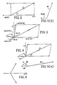
- the composite NTSC video signal is generated from a luminance component Y and two color difference or chrominance components (R-Y) and (B-Y) by employing the two chrominance components to modulate respective continuous wave (c.w.) reference subcarrier signals which are in phase quadrature, combining the two modulated subcarrier signals, and adding the luminance component to the combined modulated subcarrier signals. If the phase of the c.w. signal that is modulated by the (B-Y) component is taken as 0° then the phase of the c.w. signal that is modulated by the (R-Y) component is 90° and the color burst of the composite signal is at a phase of 180°.
- the burst and chrominance vectors are illustrated in FIG. 2.
- the digital signals provided by the control knobs are applied to a processor 34 and the values of Y, ⁇ and M are written into a random access memory 38.
- the processor operates on the luminance, hue and saturation values in accordance with a program stored in a program memory 42 and utilizing calibration constants stored in the random access memory 38, and generates values C1 and C2.
- the operations that are performed on the values of Y, ⁇ and M to generate the values C1 and C2 will be described in further detail below.
- the processor 34 also generates values A1 and A2.
- the processor provides two multiplexed digital output signals within each vertical blanking interval of the black burst signal.
- the successive words of the first signal represent values of A1, A2, X, X and zero, where X is an arbitrary (don't care) value, and are applied to a first digital-to-analog converter (DAC) 112 which provides at its output terminal an analog signal of which the voltage during successive clock intervals of the first signal represents the values of A1, A2, X, X and zero.
- the analog output signal of the DAC 112 is applied to five samples and holds 1141 . . . 1455, each of which comprises a switch 116, a capacitor 118 and an amplifier 120.
- the output voltages of the amplifiers 1201 . . . 1205 represent A1, A2, X, X and zero respectively.
- the output terminals of the amplifiers 1201 and 1203 are connected by way of respective switches 1221 and 1223 to a terminal 1241 and similarly the output terminals of the amplifiers 1202 and 1204 are connected by switches 1222 and 1224 to a terminal 1242.
- the terminals 124 are connected to a quadrature modulator 126.
- the switches 1221 and 1222 remain closed and the switches 1223 and 1224 remain open.
- the quadrature modulator 126 comprises two modulators 131 and 132 which have modulating inputs at which they receive the signals at the terminals 1241 and 1242 respectively and have carrier inputs at which they receive the reference subcarrier signal.
- a delay line 134 is connected in the path to the carrier inputs of the modulator 132. The delay line interposes a delay of (90-Q)/360 times the period of the reference subcarrier signal, with Q ideally being zero.
- the output signal provided by the quadrature modulator 126 is combined with the output signal of the amplifier 1205 in a filter and blanker 136 and the resulting signal is applied through a switch 138 to a summing amplifier 140.
- the successive words of the second signal provided by the processor represent the values of C1, C2, X, X and Y and are applied to DAC 212, sample and hold 214, quadrature modulator 226 and filter and blanker 236 which operate in essentially identical fashion to the DAC 112, the sample and hold 114, the quadrature modulator 126 and the filter and blanker 136 respectively.
- the output signal of the filter and blanker 236 is applied through a switch 238 to the summing amplifier, which also receives the horizontal and vertical sync signals.
- the controller operates the switches 138 and 238 to select the modulator 126 during only the burst interval of each active line in the field of the reference video signal and to select the modulator 226 during only the active picture interval.
- the output signal of the amplifier 140 comprises a front porch interval, followed by a horizontal sync pulse and a back porch interval.
- the output signal of the amplifier 140 is not given by the vectors (-Mb, 0) and (B-Y, R-Y), where Mb represents nominal burst amplitude, but by vectors having components (-M1A1+01, -M2A2+02) and (M1 ⁇ C1+01 ⁇ , M2 ⁇ C2+02 ⁇ ) along axes which are not mutually perpendicular but are disposed at angles of 90°-Q and 90°-Q ⁇ , as shown in FIG. 3.
- the offset, gain and quadrature errors result in the color represented by the matte signal not conforming to the desired color set by the operator interface controls.
- A1, A2, C1 and C2 it is possible to choose the values of A1, A2, C1 and C2 to compensate for the offset, gain and quadrature errors.
- the values of M1, M2, M1 ⁇ , M2 ⁇ , 01, 02, 01 ⁇ , 02 ⁇ , Q and Q ⁇ are derived by the processor 34 and are used as calibration constants in calculating suitable values of A1, A2, C1 and C2.
- the matte generator 2 includes a calibration circuit 40.
- the calibration circuit 40 comprises an input section 44 which receives both the output signal of the matte generator and two D.C. calibration voltages provided by a calibration voltage source 48.
- the input section 44 includes switches 52, 54 and 56 for selecting the matte signal or one of the calibration voltages.
- a noise reduction filter 58 is connected to the switch 52.
- a switch 60 is used to connect the output terminal of the filter 58 to the output terminal 62 of the input section 44 either directly or by way of an A.C. blocking filter 64.
- the output signal provided by the input section 44 is applied to both an amplitude detector and a burst/picture sample generator 68.
- the amplitude detector comprises a switch 70 and a peak detector 72. Assuming that the switch 70 is closed when a first signal is applied to the amplitude detector, the peak de tector provides a signal representative of the peak value of the first signal. The peak value signal is converted to digital form by an analog-to-digital converter 80 and is applied to the processor 34, which stores the digitized peak value. When a second signal is applied to the amplitude detector, the digitized peak value of the second signal is applied to the processor 34, and the difference between the two digital values is determined.
- the burst/picture sample generator 68 has an output terminal which is connected to the amplitude detector to control the state of the switch 70.
- the burst/picture sample generator causes the switch 70 to close during the burst interval or the picture interval of the matte signal, depending on which of the quadrature modulators is being calibrated.
- the calibration of the modulator 126 involves calculating the values of the offset, gain and quadrature calibration constants O1, O2, M1, M2 and Q.
- the offset and gain calibration constants can be calculated using conventional techniques.
- the quadrature calibration constant can be derived by comparing the peak values that are obtained for vectors that are ideally at +45° and -45° with reference to the (B-Y) axis and adjusting the value of Q until the peak values are equal.
- the values of 01, 02, M1, M2 and Q are used to determine the values of A1 and A2 such that the resultant of the vector having the components (-M1A1+01, -M2A2+02) at an angle of 90°-Q is identical to the vectors having the components (-Mb, 0) at 90°, as shown in FIG. 4.
- the matte signal provided by the matte generator represents the solid color selected by the operator.
- the matte signal may be adjusted to bring its burst into phase with the burst of the external video signal manually, with the aid of a vector monitor, but it is preferred that the adjustment be accomplished automatically, by use of a phase detector 88.
- phase calibration may be carried out automatically is described in co-pending application Serial No. filed (Attorney Docket No. USA 4298), the disclosure of which is hereby incorporated by reference herein.
- the phase relationship between the R-Y chrominance component and burst changes on alternate lines, and accordingly the chromaticity information in the video signal can be represented by a vector having the components (R-Y, B-Y) or a vector having the components (-[R-Y], B-Y) depending on whether the line is odd-numbered or even-numbered.
- the chromaticity information is then represented on a vector monitor as two vectors which are symmetrically disposed about the B-Y axis, as shown in FIG. 6. If the phase offset P is not an integral multiple of 90°, the components that are necessary to provide the appropriate chromaticity vector on odd-numbered lines are different from those required to produce the vector required on even-numbered lines.
- the successive words in the second output signal of the processor represent the values of C1, C2, C3, C4 and Y and the analog output voltages of the amplifiers represent C1, C2, C3, C4 and Y.
- the switches 2201 and 2202 are closed on odd-numbered lines and the switches 2203 and 2204 are closed on even-numbered lines. It will be understood that if the modulators were ideal, the output signal of the amplifier 134 would be a full-field baseband composite signal which conforms to the PAL standard and represents a matte of uniform color. In the PAL system, the subcarrier frequency is 4.43 MHz.
- the matte signal may not be necessary for the matte signal to include a color burst, and in such a case the DAC 112, sample and hold 114, modulator 126 and filter and blanker 136 would not be required, and it would only be necessary to calibrate the modulator 226 by reference to the chromaticity information in the picture interval.
- the burst/picture sample generator 68 would close the switch 70 during the picture interval instead of the burst interval, because the burst would be absent.
- the matte signal did not include a color burst, it would be necessary that the modulation axes of the matte signal be aligned with those of the external video signal in order to ensure that the phase relationship between the matte signal and the burst of the external video signal defines a color which lies inside the boundary of valid NTSC color space.
Landscapes
- Engineering & Computer Science (AREA)
- Multimedia (AREA)
- Signal Processing (AREA)
- Processing Of Color Television Signals (AREA)
Applications Claiming Priority (2)
| Application Number | Priority Date | Filing Date | Title |
|---|---|---|---|
| US07/032,140 US4758880A (en) | 1987-03-27 | 1987-03-27 | Video matte generator |
| US32140 | 1987-03-27 |
Publications (3)
| Publication Number | Publication Date |
|---|---|
| EP0284108A2 true EP0284108A2 (fr) | 1988-09-28 |
| EP0284108A3 EP0284108A3 (en) | 1990-11-07 |
| EP0284108B1 EP0284108B1 (fr) | 1993-08-11 |
Family
ID=21863309
Family Applications (1)
| Application Number | Title | Priority Date | Filing Date |
|---|---|---|---|
| EP88104994A Expired - Lifetime EP0284108B1 (fr) | 1987-03-27 | 1988-03-28 | Générateur de masque vidéo |
Country Status (5)
| Country | Link |
|---|---|
| US (1) | US4758880A (fr) |
| EP (1) | EP0284108B1 (fr) |
| JP (1) | JPH0728421B2 (fr) |
| CA (1) | CA1279723C (fr) |
| DE (1) | DE3883039T2 (fr) |
Cited By (5)
| Publication number | Priority date | Publication date | Assignee | Title |
|---|---|---|---|---|
| US7119221B2 (en) | 2003-01-23 | 2006-10-10 | Esperion Therapeutics, Inc. | Cycloalkyl-hydroxyl compounds and compositions for cholesterol management and related uses |
| US7417067B2 (en) | 1999-10-15 | 2008-08-26 | Sucampo Ag | Composition and method for stabilizing the same |
| US10912751B2 (en) | 2015-03-13 | 2021-02-09 | Esperion Therapeutics, Inc. | Fixed dose combinations and formulations comprising ETC1002 and ezetimibe and methods of treating or reducing the risk of cardiovascular disease |
| US11116739B2 (en) | 2015-03-16 | 2021-09-14 | Esperion Therapeutics, Inc. | Fixed dose combinations and formulations comprising ETC1002 and one or more statins and methods of treating or reducing cardiovascular disease |
| US11407705B2 (en) | 2019-06-21 | 2022-08-09 | Esperion Therapeutics, Inc. | Methods of making bempedoic acid and compositions of the same |
Families Citing this family (3)
| Publication number | Priority date | Publication date | Assignee | Title |
|---|---|---|---|---|
| EP0341989B1 (fr) * | 1988-05-11 | 1996-09-04 | Nec Corporation | Appareil pour générer plusieurs signaux d'image simultanés à partir d'un signal vidéo, comprenant un seul convertisseur digital-analogique |
| US4963977A (en) * | 1988-12-21 | 1990-10-16 | The Grass Valley Group, Inc. | Apparatus for generating a video signal representing a field of spatially varying color |
| US8406283B2 (en) * | 2009-07-20 | 2013-03-26 | Advantest Corporation | Modulation apparatus, test apparatus and correction method |
Family Cites Families (4)
| Publication number | Priority date | Publication date | Assignee | Title |
|---|---|---|---|---|
| JPS6013636B2 (ja) * | 1979-10-09 | 1985-04-08 | 株式会社 アサカ | テレビカメラ自動位相調整装置 |
| JPS60170075A (ja) * | 1984-02-14 | 1985-09-03 | Sony Corp | デイジタルビデオ信号処理装置 |
| GB2158319A (en) * | 1984-04-26 | 1985-11-06 | Philips Electronic Associated | A method of and apparatus for generating colour matte signals |
| US4680621A (en) * | 1985-09-16 | 1987-07-14 | Tektronix, Inc. | Method and apparatus for variable phasing of periodic signals |
-
1987
- 1987-03-27 US US07/032,140 patent/US4758880A/en not_active Expired - Fee Related
-
1988
- 1988-03-25 CA CA000562555A patent/CA1279723C/fr not_active Expired - Fee Related
- 1988-03-26 JP JP63073041A patent/JPH0728421B2/ja not_active Expired - Lifetime
- 1988-03-28 EP EP88104994A patent/EP0284108B1/fr not_active Expired - Lifetime
- 1988-03-28 DE DE88104994T patent/DE3883039T2/de not_active Expired - Fee Related
Cited By (33)
| Publication number | Priority date | Publication date | Assignee | Title |
|---|---|---|---|---|
| US7417067B2 (en) | 1999-10-15 | 2008-08-26 | Sucampo Ag | Composition and method for stabilizing the same |
| US8097649B1 (en) | 1999-10-15 | 2012-01-17 | Sucampo Ag | Composition and method for stabilizing the same |
| US8088934B2 (en) | 1999-10-15 | 2012-01-03 | Sucampo Ag | Composition and method for stabilizing the same |
| US9006290B2 (en) | 2003-01-23 | 2015-04-14 | Esperion Therapeutics, Inc. | Cycloalkyl-hydroxyl compounds and compositions for cholesterol management and related uses |
| US10047028B2 (en) | 2003-01-23 | 2018-08-14 | Esperion Therapeutics, Inc. | Cycloalkyl-hydroxyl compounds and compositions for cholesterol management and related uses |
| US7576130B2 (en) | 2003-01-23 | 2009-08-18 | Esperion Therapeutics, Inc. | Dihydroxyl compounds and compositions for cholesterol management and related uses |
| US7812199B2 (en) | 2003-01-23 | 2010-10-12 | Esperion Therapeutics, Inc. | Hydroxyl compounds and compositions for cholesterol management and related uses |
| US7838554B2 (en) | 2003-01-23 | 2010-11-23 | Esperion Therapeutics, Inc. | Dihydroxyl compounds and compositions for cholesterol management and related uses |
| US8067466B2 (en) | 2003-01-23 | 2011-11-29 | Esperion Therapeutics, Inc. | Cycloalkyl-hydroxyl compounds and compositions for cholesterol management |
| US7335799B2 (en) | 2003-01-23 | 2008-02-26 | Esperion Therapeutics, Inc. | Hydroxyl compounds and compositions for cholesterol management and related uses |
| US7335689B2 (en) | 2003-01-23 | 2008-02-26 | Esperion Therapeutics, Inc. | Dihydroxyl compounds and compositions for cholesterol management and related uses |
| US8153690B2 (en) | 2003-01-23 | 2012-04-10 | Esperion Therapeutics, Inc. | Cycloalkyl-hydroxyl compounds and compositions for cholesterol management |
| US8309604B2 (en) | 2003-01-23 | 2012-11-13 | Esperion Therapeutics, Inc. | Cycloalkyl-hydroxyl compounds and compositions for cholesterol management and related uses |
| US8497301B2 (en) | 2003-01-23 | 2013-07-30 | Esperion Therapeutics, Inc. | Hydroxyl compounds and compositions for cholesterol management and related uses |
| US8623915B2 (en) | 2003-01-23 | 2014-01-07 | Esperion Therapeutics, Inc. | Cycloalkyl-hydroxyl compounds and compositions for cholesterol management and related uses |
| US9000041B2 (en) | 2003-01-23 | 2015-04-07 | Esperion Therapeutics, Inc. | Hydroxyl compounds and compositions for cholesterol management and related uses |
| US7119221B2 (en) | 2003-01-23 | 2006-10-10 | Esperion Therapeutics, Inc. | Cycloalkyl-hydroxyl compounds and compositions for cholesterol management and related uses |
| US7405226B2 (en) | 2003-01-23 | 2008-07-29 | Pfizer Inc. | Cycloalkyl-hydroxyl compounds and compositions for cholesterol management and related uses |
| US9452964B2 (en) | 2003-01-23 | 2016-09-27 | Esperion Therapeutics, Inc. | Cycloalkyl-hydroxyl compounds and compositions for cholesterol management and related uses |
| US9624152B2 (en) | 2003-01-23 | 2017-04-18 | Esperion Therapeutics, Inc. | Hydroxyl compounds and compositions for cholesterol management and related uses |
| US10118881B2 (en) | 2003-01-23 | 2018-11-06 | Esperion Therapeutics, Inc. | Hydroxyl compounds and compositions for cholesterol management and related uses |
| US10941095B2 (en) | 2003-01-23 | 2021-03-09 | Esperion Therapeutics, Inc. | Hydroxyl compounds and compositions for cholesterol management and related uses |
| US10912751B2 (en) | 2015-03-13 | 2021-02-09 | Esperion Therapeutics, Inc. | Fixed dose combinations and formulations comprising ETC1002 and ezetimibe and methods of treating or reducing the risk of cardiovascular disease |
| US11744816B2 (en) | 2015-03-13 | 2023-09-05 | Esperion Therapeutics, Inc. | Fixed dose combinations and formulations comprising ETC1002 and ezetimibe and methods of treating or reducing the risk of cardiovascular disease |
| US11116739B2 (en) | 2015-03-16 | 2021-09-14 | Esperion Therapeutics, Inc. | Fixed dose combinations and formulations comprising ETC1002 and one or more statins and methods of treating or reducing cardiovascular disease |
| US11613511B2 (en) | 2019-06-21 | 2023-03-28 | Esperion Therapeutics, Inc. | Methods of making bempedoic acid and compositions of the same |
| US11407705B2 (en) | 2019-06-21 | 2022-08-09 | Esperion Therapeutics, Inc. | Methods of making bempedoic acid and compositions of the same |
| US11760714B2 (en) | 2019-06-21 | 2023-09-19 | Esperion Therapeutics, Inc. | Methods of making bempedoic acid and compositions of the same |
| US11926584B2 (en) | 2019-06-21 | 2024-03-12 | Esperion Therapeutics, Inc. | Methods of making bempedoic acid and compositions of the same |
| US11987548B2 (en) | 2019-06-21 | 2024-05-21 | Esperion Therapeutics, Inc. | Methods of making bempedoic acid and compositions of the same |
| US12344578B2 (en) | 2019-06-21 | 2025-07-01 | Esperion Therapeutics, Inc. | Salt forms of bempedoic acid and methods for using the same |
| US12398087B2 (en) | 2019-06-21 | 2025-08-26 | Esperion Therapeutics, Inc. | Methods of making bempedoic acid and compositions of the same |
| US12404227B2 (en) | 2019-06-21 | 2025-09-02 | Esperion Therapeutics, Inc. | Methods of making bempedoic acid and compositions of the same |
Also Published As
| Publication number | Publication date |
|---|---|
| DE3883039D1 (en) | 1993-09-16 |
| JPS63261977A (ja) | 1988-10-28 |
| US4758880A (en) | 1988-07-19 |
| JPH0728421B2 (ja) | 1995-03-29 |
| CA1279723C (fr) | 1991-01-29 |
| EP0284108B1 (fr) | 1993-08-11 |
| EP0284108A3 (en) | 1990-11-07 |
| DE3883039T2 (de) | 1994-03-03 |
Similar Documents
| Publication | Publication Date | Title |
|---|---|---|
| US6014176A (en) | Automatic phase control apparatus for phase locking the chroma burst of analog and digital video data using a numerically controlled oscillator | |
| US4533938A (en) | Color modifier for composite video signals | |
| US3950780A (en) | Vir chroma system | |
| US6177962B1 (en) | Apparatus and method for preventing oversaturation of chrominance signals | |
| EP0284108B1 (fr) | Générateur de masque vidéo | |
| US4183050A (en) | Clamping circuit for color television signals | |
| US4953008A (en) | Method and apparatus for uniform saturation, hue and luminance correction | |
| US4754321A (en) | Integratable color correction circuit | |
| EP0285078B1 (fr) | Méthode et dispositif de calibrage de la phase d'un signal vidéo | |
| EP0785690B1 (fr) | Réglage de la phase entre la sous-porteuse et la synchronisation horizontale pour des signaux de test vidéo synthetisés numériquement | |
| US5396296A (en) | Video feedback matching circuit and method therefor | |
| EP0620692B1 (fr) | Circuit de détection de teinte | |
| EP0818034B1 (fr) | Reglage du niveau de noir | |
| EP0767590A1 (fr) | Procede et circuit de synchronisation de phase d'un signal video, et dispositif combine | |
| US3717727A (en) | Color shifting circuit for a color television display apparatus | |
| US5122865A (en) | Chroma key signal generator for a video editing apparatus | |
| US4184173A (en) | Color television receiving apparatus | |
| EP0588169B1 (fr) | Récepteur de télévision avec entrée vidéo auxiliaire verrouillée | |
| KR100211462B1 (ko) | 텔레비젼 수상기의 화이트밸런스 조정장치 | |
| US4156251A (en) | Color television receiving apparatus | |
| US3878558A (en) | Phase compensating system | |
| GB2052208A (en) | Encoding circuit for a secam transmission | |
| EP0221254A2 (fr) | Dispositif de réglage de teinte | |
| EP0696142A2 (fr) | Circuits de contrÔle pour ajuster la tension de blocage et la tension de commande et équipement vidéo incorporant ceux-ci | |
| JPH05316542A (ja) | 色相調整装置 |
Legal Events
| Date | Code | Title | Description |
|---|---|---|---|
| PUAI | Public reference made under article 153(3) epc to a published international application that has entered the european phase |
Free format text: ORIGINAL CODE: 0009012 |
|
| AK | Designated contracting states |
Kind code of ref document: A2 Designated state(s): DE FR GB NL |
|
| PUAL | Search report despatched |
Free format text: ORIGINAL CODE: 0009013 |
|
| AK | Designated contracting states |
Kind code of ref document: A3 Designated state(s): DE FR GB NL |
|
| 17P | Request for examination filed |
Effective date: 19901102 |
|
| 17Q | First examination report despatched |
Effective date: 19921202 |
|
| GRAA | (expected) grant |
Free format text: ORIGINAL CODE: 0009210 |
|
| AK | Designated contracting states |
Kind code of ref document: B1 Designated state(s): DE FR GB NL |
|
| PG25 | Lapsed in a contracting state [announced via postgrant information from national office to epo] |
Ref country code: NL Effective date: 19930811 Ref country code: FR Effective date: 19930811 |
|
| REF | Corresponds to: |
Ref document number: 3883039 Country of ref document: DE Date of ref document: 19930916 |
|
| EN | Fr: translation not filed | ||
| NLV1 | Nl: lapsed or annulled due to failure to fulfill the requirements of art. 29p and 29m of the patents act | ||
| PLBE | No opposition filed within time limit |
Free format text: ORIGINAL CODE: 0009261 |
|
| STAA | Information on the status of an ep patent application or granted ep patent |
Free format text: STATUS: NO OPPOSITION FILED WITHIN TIME LIMIT |
|
| 26N | No opposition filed | ||
| PGFP | Annual fee paid to national office [announced via postgrant information from national office to epo] |
Ref country code: GB Payment date: 19970220 Year of fee payment: 10 |
|
| PGFP | Annual fee paid to national office [announced via postgrant information from national office to epo] |
Ref country code: DE Payment date: 19970224 Year of fee payment: 10 |
|
| PG25 | Lapsed in a contracting state [announced via postgrant information from national office to epo] |
Ref country code: GB Free format text: LAPSE BECAUSE OF NON-PAYMENT OF DUE FEES Effective date: 19980328 |
|
| GBPC | Gb: european patent ceased through non-payment of renewal fee |
Effective date: 19980328 |
|
| PG25 | Lapsed in a contracting state [announced via postgrant information from national office to epo] |
Ref country code: DE Free format text: LAPSE BECAUSE OF NON-PAYMENT OF DUE FEES Effective date: 19981201 |