EP0284293A2 - Mehrstrecken-Lichtwellenübertragungsnetz mit mehreren Kanälen - Google Patents
Mehrstrecken-Lichtwellenübertragungsnetz mit mehreren Kanälen Download PDFInfo
- Publication number
- EP0284293A2 EP0284293A2 EP88302349A EP88302349A EP0284293A2 EP 0284293 A2 EP0284293 A2 EP 0284293A2 EP 88302349 A EP88302349 A EP 88302349A EP 88302349 A EP88302349 A EP 88302349A EP 0284293 A2 EP0284293 A2 EP 0284293A2
- Authority
- EP
- European Patent Office
- Prior art keywords
- nius
- communication
- network
- niu
- channels
- Prior art date
- Legal status (The legal status is an assumption and is not a legal conclusion. Google has not performed a legal analysis and makes no representation as to the accuracy of the status listed.)
- Granted
Links
- 238000004891 communication Methods 0.000 title claims abstract description 40
- 230000001902 propagating effect Effects 0.000 claims description 2
- 230000003134 recirculating effect Effects 0.000 claims description 2
- 238000001228 spectrum Methods 0.000 claims 1
- 230000003287 optical effect Effects 0.000 abstract description 20
- 238000000034 method Methods 0.000 abstract description 5
- 235000008694 Humulus lupulus Nutrition 0.000 abstract 1
- 230000005540 biological transmission Effects 0.000 description 9
- 239000013307 optical fiber Substances 0.000 description 9
- 238000013459 approach Methods 0.000 description 6
- 238000010586 diagram Methods 0.000 description 4
- 238000005516 engineering process Methods 0.000 description 4
- 239000000835 fiber Substances 0.000 description 3
- 239000000872 buffer Substances 0.000 description 2
- 239000000969 carrier Substances 0.000 description 2
- 238000001914 filtration Methods 0.000 description 2
- 230000003321 amplification Effects 0.000 description 1
- 230000001427 coherent effect Effects 0.000 description 1
- 238000013461 design Methods 0.000 description 1
- 238000001514 detection method Methods 0.000 description 1
- 238000007599 discharging Methods 0.000 description 1
- 230000000694 effects Effects 0.000 description 1
- 238000012986 modification Methods 0.000 description 1
- 230000004048 modification Effects 0.000 description 1
- 238000003199 nucleic acid amplification method Methods 0.000 description 1
- 238000012545 processing Methods 0.000 description 1
- 230000003252 repetitive effect Effects 0.000 description 1
Images





Classifications
-
- H—ELECTRICITY
- H04—ELECTRIC COMMUNICATION TECHNIQUE
- H04B—TRANSMISSION
- H04B10/00—Transmission systems employing electromagnetic waves other than radio-waves, e.g. infrared, visible or ultraviolet light, or employing corpuscular radiation, e.g. quantum communication
-
- H—ELECTRICITY
- H04—ELECTRIC COMMUNICATION TECHNIQUE
- H04J—MULTIPLEX COMMUNICATION
- H04J14/00—Optical multiplex systems
- H04J14/02—Wavelength-division multiplex systems
- H04J14/0227—Operation, administration, maintenance or provisioning [OAMP] of WDM networks, e.g. media access, routing or wavelength allocation
-
- H—ELECTRICITY
- H04—ELECTRIC COMMUNICATION TECHNIQUE
- H04J—MULTIPLEX COMMUNICATION
- H04J14/00—Optical multiplex systems
- H04J14/02—Wavelength-division multiplex systems
- H04J14/0227—Operation, administration, maintenance or provisioning [OAMP] of WDM networks, e.g. media access, routing or wavelength allocation
- H04J14/0241—Wavelength allocation for communications one-to-one, e.g. unicasting wavelengths
- H04J14/0242—Wavelength allocation for communications one-to-one, e.g. unicasting wavelengths in WDM-PON
- H04J14/0245—Wavelength allocation for communications one-to-one, e.g. unicasting wavelengths in WDM-PON for downstream transmission, e.g. optical line terminal [OLT] to ONU
- H04J14/0246—Wavelength allocation for communications one-to-one, e.g. unicasting wavelengths in WDM-PON for downstream transmission, e.g. optical line terminal [OLT] to ONU using one wavelength per ONU
-
- H—ELECTRICITY
- H04—ELECTRIC COMMUNICATION TECHNIQUE
- H04J—MULTIPLEX COMMUNICATION
- H04J14/00—Optical multiplex systems
- H04J14/02—Wavelength-division multiplex systems
- H04J14/0227—Operation, administration, maintenance or provisioning [OAMP] of WDM networks, e.g. media access, routing or wavelength allocation
- H04J14/0241—Wavelength allocation for communications one-to-one, e.g. unicasting wavelengths
- H04J14/0242—Wavelength allocation for communications one-to-one, e.g. unicasting wavelengths in WDM-PON
- H04J14/0245—Wavelength allocation for communications one-to-one, e.g. unicasting wavelengths in WDM-PON for downstream transmission, e.g. optical line terminal [OLT] to ONU
- H04J14/0247—Sharing one wavelength for at least a group of ONUs
-
- H—ELECTRICITY
- H04—ELECTRIC COMMUNICATION TECHNIQUE
- H04J—MULTIPLEX COMMUNICATION
- H04J14/00—Optical multiplex systems
- H04J14/02—Wavelength-division multiplex systems
- H04J14/0227—Operation, administration, maintenance or provisioning [OAMP] of WDM networks, e.g. media access, routing or wavelength allocation
- H04J14/0241—Wavelength allocation for communications one-to-one, e.g. unicasting wavelengths
- H04J14/0242—Wavelength allocation for communications one-to-one, e.g. unicasting wavelengths in WDM-PON
- H04J14/0249—Wavelength allocation for communications one-to-one, e.g. unicasting wavelengths in WDM-PON for upstream transmission, e.g. ONU-to-OLT or ONU-to-ONU
- H04J14/025—Wavelength allocation for communications one-to-one, e.g. unicasting wavelengths in WDM-PON for upstream transmission, e.g. ONU-to-OLT or ONU-to-ONU using one wavelength per ONU, e.g. for transmissions from-ONU-to-OLT or from-ONU-to-ONU
-
- H—ELECTRICITY
- H04—ELECTRIC COMMUNICATION TECHNIQUE
- H04J—MULTIPLEX COMMUNICATION
- H04J14/00—Optical multiplex systems
- H04J14/02—Wavelength-division multiplex systems
- H04J14/0227—Operation, administration, maintenance or provisioning [OAMP] of WDM networks, e.g. media access, routing or wavelength allocation
- H04J14/0241—Wavelength allocation for communications one-to-one, e.g. unicasting wavelengths
- H04J14/0242—Wavelength allocation for communications one-to-one, e.g. unicasting wavelengths in WDM-PON
- H04J14/0249—Wavelength allocation for communications one-to-one, e.g. unicasting wavelengths in WDM-PON for upstream transmission, e.g. ONU-to-OLT or ONU-to-ONU
- H04J14/0252—Sharing one wavelength for at least a group of ONUs, e.g. for transmissions from-ONU-to-OLT or from-ONU-to-ONU
-
- H—ELECTRICITY
- H04—ELECTRIC COMMUNICATION TECHNIQUE
- H04L—TRANSMISSION OF DIGITAL INFORMATION, e.g. TELEGRAPHIC COMMUNICATION
- H04L12/00—Data switching networks
- H04L12/28—Data switching networks characterised by path configuration, e.g. LAN [Local Area Networks] or WAN [Wide Area Networks]
-
- H—ELECTRICITY
- H04—ELECTRIC COMMUNICATION TECHNIQUE
- H04J—MULTIPLEX COMMUNICATION
- H04J14/00—Optical multiplex systems
- H04J14/02—Wavelength-division multiplex systems
- H04J14/0278—WDM optical network architectures
- H04J14/028—WDM bus architectures
-
- H—ELECTRICITY
- H04—ELECTRIC COMMUNICATION TECHNIQUE
- H04J—MULTIPLEX COMMUNICATION
- H04J14/00—Optical multiplex systems
- H04J14/02—Wavelength-division multiplex systems
- H04J14/0278—WDM optical network architectures
- H04J14/0282—WDM tree architectures
Definitions
- the present invention relates to a multichannel, multihop, lightwave communications network which allows a plurality of user data packets to concurrently reside within the network while avoiding the need for agile optical components.
- lightwave For long distance point-to-point communications, lightwave has emerged as the technology of choice. When applied to multiuser local systems, lightwave technology has the potential for enormous bandwidth for each end user, coupled with the corresponding opportunity to offer revolutionary new user services and capabilities based on an abundance of inexpensive bandwidth. However, the reality of lightwave networks is somewhat at variance with this potential. Compared with twisted pair, coaxial cable, or radio based networks with active electronic circuitry, lightwave is a relatively immature technology.
- the lightwave transmission medium possesses a bandwidth which might be measured in the tens of terahertz range, the ability of any particular user to access the bandwidth, to either receive or transmit, through a single user port on the network is limited by the rate at which light may be electro-optically modulated or demodulated, a rate limited to the range of several gigabits/sec.
- Time and frequency (or wavelength) division multiplexing are the two most common methods for sharing a communications channel among multiple users.
- T. S. Kinsel and O. E. DeLange relating to time division multiplexing and frequency division multiplexing, respectively, for wide-band optical communication systems in Proceedings of the IEEE , Vol. 58, No. 10, October 1970, at respective pages 1666-1682 and 1683-1690.
- WDM Wavelength-Division Multiplexing
- each transmitting node be instantaneously connected to the corresponding receiving node.
- the current state of the art of lightwave technology cannot provide the dynamic agility needed to appropriately interconnect user pairs. Therefore, the problem in the prior art is to provide a lightwave network which achieves concurrency of multiple transmissions between network user pairs while avoiding the need for dynamic agility.
- the present invention relates to a multichannel, multihop, lightwave communications network which allows a plurality of user data packets to concurrently propagate within the network while avoiding the need for agile optical components. More particularly, the present invention relates to a lightwave communication network comprising a lightwave communication medium for supporting a plurality of independent user nodes; and a plurality of N network interface units (NIU), each NIU being connected to the lightwave communication medium and one or more separate user nodes of the network and comprising one or more transmitters and receivers which are each separately fixedly assigned to transmit and receive, respectively, over a single communication channel.
- NNIU N network interface units
- Communication channels and NIU transmitters and receivers are assigned such that at least one NIU can transmit to at least two other NIUs or receive from at least two other NIUs, and there is at least one NIU that cannot transmit directly via a communication channel to at least one other NIU.
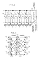
- FIGs. 1-3 show an exemplary approach for the present multihop lightwave network, which for simplicity, is drawn for a bus topology. It is to be understood that this exemplary approach is merely being used for purposes of explanation and not for purposes of limitation and that such approach can be expanded to cover a broader aspect of the present invention by including other network topologies and component transmission and reception assignments as will be described hereinafter.
- the individual users, or individual groups of users, in the network interface with two unidirectional lightwave busses 10 a and 10 b , which are interconnected at a head end 12 and can be formed from a single lightguide, such as an optical fiber, or multiple lightguides via a sequence of Network Interface Units (NIUs) 110 to 117 which are distributed along the busses. All NIUs transmit onto the transmit bus 10 a which unidirectionally propagates all messages toward head end 12 where the optical lightguide forming the busses passively loops back for propagating the messages or packets over broadcast bus 10 b to NIUs 110 to 117.
- FIG. 1 depicts an exemplary network of FIG. 2 where, for example, sixteen Wavelength-Division-Multiplexed (WDM) channels are created within the single fiber bus 10 a and 10 b
- WDM Wavelength-Division-Multiplexed
- Each NIU 11 i of this network is equipped with two laser transmitters which, for simplicity will be assumed as single mode lasers, although multimode lasers may also be used as long as the channels remain distinct.
- Each of the two optical transmitters in each NIU is permanently tuned to one of the sixteen WDM channels and may be modulated at a user rate of, for example, 1 Gb/sec.
- each NIU can transmit only over two channels to which it has been assigned at the maximum rate of the exemplary 1 Gb/sec.
- each NIU is equipped with two receivers, each of which is permanently tuned to receive one of the WDM channels at the exemplary channel rate of 1 Gb/sec.
- Channel selection may be performed either with two narrowband optical filters to select the appropriate two channels, or via coherent heterodyne detection where, the receivers would contain two single mode lasers with each laser tuned to receive the appropriate channel as shown in FIG. 4 and described in more detail hereinafter.
- the multihop network of FIG. 1 can also be used to described a non-WDM, multihop, star network where the lines depicting the separate channels on busses 10 a and 10 b can be separate optical fibers which are patched at the head end to interconnect the appropriate NIU pairs. More particularly, the first and second transmitter of NIU 110 would transmit over separate optical fibers shown as the lines for channels 9 and 11, respectively, which would be patched or connected at the head end to respective separate optical fibers indicated as channels 9 and 11 that are terminated in one of the two receivers of NIUs 114 and 115, respectively. The other NIUs would similarly be connected to separate optical fibers and terminated at a separate receiver of the associated NIU pairs. Therefore, the term channel hereinafter can designate either a separate WDM frequency band or a separate dedicated optical fiber. Moreover, the complete set of channels used in the network may be derived from the combination of WDM on multiple optical fibers.
- NIUs with 16 WDM channels or dedicated fibers of FIG. 1, it is shown that no two transmitters transmit over the same channel and no two receivers listen to the same channel, and the channel assignments have been made such that only one receiver listens to each of the channels.
- user node 0, employing NIU 110 can only transmit over channels 9 and 11 which can only be received by NIU 114 and NIU 115, respectively.
- the optical channel assignment among NIU pairs takes the form of a re-circulating perfect shuffle interconnection pattern as shown in FIG. 3.
- the NIUs are grouped into two columns with NIUs 110 to 113 disposed in the first column and NIUs 114 to 117 disposed in the second column.
- each NIU block corresponds to the transmit direction
- the left-hand side corresponds to the receive direction.
- the interconnection between the transmitters of column 1 and the receivers of column 2 takes the form of a perfect shuffle pattern.
- the interconnection between the transmitters of column 2 and the receivers of column 1 also takes the form of a perfect shuffle.
- the perfect shuffle pattern insures that, for such an exemplary eight user node network, every message can find its way to the correct destination by either a direct connection or by hopping along paths transversed by intermediate NIUs, and no message must be introduced to the network more than three times.
- user node 6 wishes to send a message or packet to user node 1.
- This message or packet will arrive at NIU 116 via the electronic interface from user node 6 where it will be (a) electronically routed in NIU 6 to the transmitter feeding channel 4, and (b) then optically received by NIU 111 from channel 4 and regenerated therein to produce an electrical signal which is transmitted via the electronic interface from NIU 111 to user node 1.
- the message will arrive from user node 0 at NIU 110 via the electronic interface where it will be (a) electronically routed to the transmitter feeding optical channel 11, (b) optically received and regenerated by NIU 115, (c) electronically routed to the transmitter of NIU 115 feeding optical channel 7, (d) optically received and regenerated by NIU 113, (e) electronically routed to the transmitter of NIU 113 feeding channel 14, and (f) optically received by NIU 116 and regenerated to produce an electrical signal which is transmitted via the electronic interface to user node 6.
- the above-described network therefore, provides concurrency of signals from the user nodes and complete interconnectivity of all users of the network while avoiding optical components which require agility.
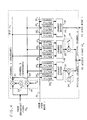
- NIU 11 i is shown as including three inputs, with the first input being the electronic interface 20 from the associated user node i.
- the two remaining inputs 21 and 22 are optical, and correspond to the two WDM receive channels from bus 10 b to which NIU 11 i is permanently assigned. Since all optical channels from bus 10 b are available to the NIU, two filtering means are needed to select the appropriate two channels. This may be done by optical heterodyning, as shown in FIG. 4, where a first demodulator 23 and a second demodulator 24 each demodulate to baseband a separate one of the two dedicated channels associated with the NIU for further processing. Alternatively, fixed narrow band optical filtering and detecting means (not shown) may be used in place of demodulators 23 and 24 to pass the desired channels while discriminating against all others and producing the two desired electronic output signals.
- the three electronic baseband signals arriving on inputs 20-22 are then distributed to a 3x3 fully interconnected electronic switching means which can take the form of three sets of three channel filters or selectors 25 a - 27 a to 25 c - 27 c .
- the three filters or selectors associated with each output e.g., selectors 25 a - 27 a associated with output 31, select those signals from each of the three inputs 20-22 intended for that particular output, and disregard the rest.
- each of the channel filters or selectors 25 i -27 i include active electronics which, for example, looks at a header field in the receiving message or packet and compares this information with stored destination addresses to determine whether the message should preferably be transmitted via the associated output or not.
- Each of the three outputs 31-33 is served by a shared buffer 28-30, respectively, which stores arriving messages for a particular output on a first in first out basis.
- outputs 31 and 32 drive optical modulators 34 and 35, respectively, to place the output signals on the appropriate channels of bus 10 a .
- the third output 33 is an electronic interface which goes directly to the associated end user node.
- inputs 21 and 22 would be directly connected to the associated optical receivers for the separate optical fibers of bus 10 b
- outputs 31 and 32 would be directly connected to the optical transmitters for the separate dedicated fibers of bus 10 a .
- k is the number of columns in the connectivity graph into which the NIUs are grouped
- p is the number of separate channels used for transmission by each NIU.
- the number of channels needed may be significantly reduced. Rather than giving each transmitter a dedicated channel to one receiver, a given channel can be shared among several transmitters, and several receivers can be allowed to receive a particular channel.
- FIG. 6 modifies this pattern to sequentially number the receiving channels in each column from 1-16 as shown. With this pattern, NIUs 0, 8, and 16 all write onto channels 1 and 3.
- the number of WDM channels created in busses 10 of FIG. 1 by the pattern of FIG. 5 is substantially reduced from 48 to 16 channels in FIG. 6, and each channel is shared among three NIUs.
- NIU 1 has a message which must be routed to NIU 10 on channel 5
- the NIU 9 has a message which must be routed to NIU 18 on channel 5
- NIUs 1 and 9 must contend for the right to use channel 5 at that time using any known contention technique; the one denied transmission must defer to some later time.
- TDMA Time Division Multiple Access
- time is divided into repetitive frames, each frame containing k time slots, and one of the k NIUs contending for a given channel is permanently assigned to one of the k time slots. If all buffers 28 and 29 of FIG. 4 in the NIUs are not empty, then no time on a channel will be lost due to the fixed TDMA assignment.
- efficient token bus access used in the past for single channel networks may be used for each of the WDM channels.
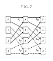
- channels may be shared among NIUs in a column as illustrated in FIG. 7. In this manner, only one transmitter and one receiver are required for each NIU.
- the present perfect shuffle networks hereinafter ShuffleNets, with only one transmitter and one receiver per NIU share WDM channels or lightguides among NIUs.
- groups of p NIUs in each column of a connectivity graph transmit on a common channel, with a separate group of p NIUs in the next column receiving each channel.
- each of the NIU pairs (0,2), (1,3), (4,6), and (5,7) transmits on a different channel with each NIU using one transmitter and one receiver.
- addresses are assigned in a natural way with columns, c, numbered left to right from 0 to k-1, and rows, r, numbered top to bottom from 0 to p k -1. Since WDM channels can be shared, with p NIUs listening to the same wavelength and receiving the same packets, the routing algorithm must specify which NIU should retransmit a received packet. Specifically, when a NIU receives a packet that is not destined to its associated user, it must determine whether it should retransmit the packet over its transmit channel, or just ignore the packet.
- ⁇ ,r ⁇ the coordinates
- ShuffleNet has two important properties that can be exploited to simplify the multiple access problem with shared channels. First, only a small fraction of the total user population contend for use of any given WDM channel. Second, the relative independence of a connectivity graph and the network physical topology provides the freedom to assign the transmit and receive wavelengths specified by ShuffleNet arbitrarily to specific NIUs. Channel. sharing can be made easier by assigning the same transmit wavelength to a group of NIUs that are "geographically close", thereby reducing the propagation delay between NIUs sharing a common channel. Furthermore, the second property may permit a network design that only requires one transmitter per channel, rather than one transmitter per NIU.
- FIG. 11 illustrates a double-star configuration as one possible physical topology for the efficient channel sharing of a single transmitter, single receiver per user ShuffleNet for the connectivity graph of FIG. 7.
- NIUs 0 and 2 are physically close and are arbitrarily assigned a transmit wavelength ⁇ 1.
- NIUs 0 and 2 receive packets on wavelengths ⁇ 3 and ⁇ 4, respectively, in accordance with the connectivity graph.
- the first packet to reach an idle collision-avoidance star 50 passes therethrough.
- the collision-avoidance star 50 is busy, a packet that arrives from any other NIU is "blocked", and must be retransmitted by the NIU. Packets that make it through on different wavelengths are combined in a star coupler 51, and broadcast back down to all NIUs via power splitters 50.
- Power splitters 52 are used to divide the received signal and transmit the signals to the associated NIUs.
- an NIU has been generally described as being associated with a single user node and having equal numbers of transmitters and receivers, an NIU may serve a plurality of m users and have i receivers and i transmitters so that the electronic switch within the NIU would comprise an (i+m)-by-(j+m) configuration.
- other connectivity graphs besides the recirculating perfect shuffle described hereinbefore are possible, where the number of incoming and outgoing links may vary from one NIU to another.
- the physical topology of a multihop network may be that of a bus, as shown in FIG. 2, other physical topologies are possible including stars, trees, rings and meshes.
Landscapes
- Engineering & Computer Science (AREA)
- Computer Networks & Wireless Communication (AREA)
- Signal Processing (AREA)
- Physics & Mathematics (AREA)
- Electromagnetism (AREA)
- Data Exchanges In Wide-Area Networks (AREA)
- Optical Communication System (AREA)
- Small-Scale Networks (AREA)
Applications Claiming Priority (2)
| Application Number | Priority Date | Filing Date | Title |
|---|---|---|---|
| US3039587A | 1987-03-26 | 1987-03-26 | |
| US30395 | 1987-03-26 |
Publications (3)
| Publication Number | Publication Date |
|---|---|
| EP0284293A2 true EP0284293A2 (de) | 1988-09-28 |
| EP0284293A3 EP0284293A3 (de) | 1991-01-23 |
| EP0284293B1 EP0284293B1 (de) | 1994-11-09 |
Family
ID=21854012
Family Applications (1)
| Application Number | Title | Priority Date | Filing Date |
|---|---|---|---|
| EP88302349A Expired - Lifetime EP0284293B1 (de) | 1987-03-26 | 1988-03-17 | Mehrstrecken-Lichtwellenübertragungsnetz mit mehreren Kanälen |
Country Status (6)
| Country | Link |
|---|---|
| EP (1) | EP0284293B1 (de) |
| JP (1) | JPH06101745B2 (de) |
| KR (1) | KR910003239B1 (de) |
| AU (1) | AU592495B2 (de) |
| CA (1) | CA1287911C (de) |
| DE (1) | DE3852053T2 (de) |
Cited By (5)
| Publication number | Priority date | Publication date | Assignee | Title |
|---|---|---|---|---|
| WO1991015790A1 (en) * | 1990-04-11 | 1991-10-17 | University Of Ottawa | Optical interconnection device |
| US5179605A (en) * | 1990-10-10 | 1993-01-12 | University Of Ottawa | Optical interconnection device |
| EP0407078A3 (en) * | 1989-07-03 | 1993-03-03 | American Telephone And Telegraph Company | Efficient connection arrangements for multihop networks |
| EP0497005A3 (en) * | 1990-12-28 | 1994-09-07 | Nec Corp | Access method for optical local area network systems |
| EP0790721A3 (de) * | 1996-02-02 | 2000-07-12 | Canon Kabushiki Kaisha | Verfahren und Vorrichtung zur Übertragungssteuerung in einem Netzwerksystem zur mehrkanaligen Signalübertragung |
Family Cites Families (6)
| Publication number | Priority date | Publication date | Assignee | Title |
|---|---|---|---|---|
| JPS6031131B2 (ja) * | 1980-02-08 | 1985-07-20 | 株式会社東芝 | 分布形光ネットワ−ク |
| JPS58139543A (ja) * | 1982-02-15 | 1983-08-18 | Ricoh Co Ltd | 通信回路網 |
| US4554656A (en) * | 1982-08-11 | 1985-11-19 | At&T Bell Laboratories | Method and system for controlling the interconnecting of a plurality of local data networks |
| FR2586874B1 (fr) * | 1985-08-29 | 1988-08-05 | Comp Generale Electricite | Dispositif de telecommunication par fibres optiques. |
| US4754452A (en) * | 1986-09-11 | 1988-06-28 | American Telephone And Telegraph Company, At&T Bell Laboratories | Optical local area network using a common optical carrier with separate user angle modulation |
| AU8121387A (en) * | 1986-11-13 | 1988-05-19 | Overseas Telecommunications Commission (Australia) | Optical fibre communication system |
-
1988
- 1988-03-15 CA CA000561518A patent/CA1287911C/en not_active Expired - Fee Related
- 1988-03-17 EP EP88302349A patent/EP0284293B1/de not_active Expired - Lifetime
- 1988-03-17 DE DE3852053T patent/DE3852053T2/de not_active Expired - Fee Related
- 1988-03-24 AU AU13572/88A patent/AU592495B2/en not_active Ceased
- 1988-03-25 JP JP6995088A patent/JPH06101745B2/ja not_active Expired - Fee Related
- 1988-03-25 KR KR1019880003209A patent/KR910003239B1/ko not_active Expired
Cited By (5)
| Publication number | Priority date | Publication date | Assignee | Title |
|---|---|---|---|---|
| EP0407078A3 (en) * | 1989-07-03 | 1993-03-03 | American Telephone And Telegraph Company | Efficient connection arrangements for multihop networks |
| WO1991015790A1 (en) * | 1990-04-11 | 1991-10-17 | University Of Ottawa | Optical interconnection device |
| US5179605A (en) * | 1990-10-10 | 1993-01-12 | University Of Ottawa | Optical interconnection device |
| EP0497005A3 (en) * | 1990-12-28 | 1994-09-07 | Nec Corp | Access method for optical local area network systems |
| EP0790721A3 (de) * | 1996-02-02 | 2000-07-12 | Canon Kabushiki Kaisha | Verfahren und Vorrichtung zur Übertragungssteuerung in einem Netzwerksystem zur mehrkanaligen Signalübertragung |
Also Published As
| Publication number | Publication date |
|---|---|
| KR910003239B1 (ko) | 1991-05-24 |
| KR880012037A (ko) | 1988-10-31 |
| EP0284293B1 (de) | 1994-11-09 |
| AU1357288A (en) | 1988-09-29 |
| DE3852053T2 (de) | 1995-03-16 |
| EP0284293A3 (de) | 1991-01-23 |
| DE3852053D1 (de) | 1994-12-15 |
| AU592495B2 (en) | 1990-01-11 |
| CA1287911C (en) | 1991-08-20 |
| JPH06101745B2 (ja) | 1994-12-12 |
| JPS63256033A (ja) | 1988-10-24 |
Similar Documents
| Publication | Publication Date | Title |
|---|---|---|
| US4914648A (en) | Multichannel, multihop lightwave communication system | |
| Mukherjee | WDM-based local lightwave networks. I. Single-hop systems | |
| Acampora et al. | Terabit lightwave networks: The multihop approach | |
| Hluchyj et al. | Shuffle net: An application of generalized perfect shuffles to multihop lightwave networks | |
| US8134939B2 (en) | Multichannel ring and star networks with limited channel conversion | |
| Senior et al. | Developments in wavelength division multiple access networking | |
| JPH10502500A (ja) | 通信用の高い伝送容量を有する伝送ネットワーク・システム | |
| KR0181718B1 (ko) | 중재 제어가 필요없는 네트워크 시스템, 이 네트워크 시스템에서 사용되는 노드 디바이스, 및 노드 디바이스용 송신 제어 방법 | |
| JPH04294656A (ja) | パケット交換機の相互結合器 | |
| Acampora et al. | Multihop lightwave networks: A new approach to achieve terabit capabilities | |
| EP0284293B1 (de) | Mehrstrecken-Lichtwellenübertragungsnetz mit mehreren Kanälen | |
| USRE35262E (en) | Efficient single-hop directional multichannel system | |
| EP1230823B1 (de) | Optisches kommunikationssystem | |
| US20030035167A1 (en) | Optical signalling system | |
| CA2391629C (en) | Optical communications system | |
| US5479287A (en) | Switchable optical network with improved transmission ability | |
| Jager | WDM-gridconnect as a transport structure | |
| Papadimitriou et al. | Wavelength-conversion-based protocols for single-hop photonic networks with bursty traffic | |
| Matsumoto | Multiple-access optical network architecture employing a wavelength-and-network-division technique: MANDALA | |
| MATSUMOTO et al. | Multiple-access optical network architecture employing a wavelength-and-network-division technique: MANDALA | |
| Hallingstad | Sparse tunability in WDM multi-hop local lightwave networks | |
| Papadimitriou et al. | A class of centralized high‐performance protocols for single‐hop lightwave networks | |
| HAN et al. | A WDM channel sharing scheme for multihop lightwave networks using logically bidirectional perfect shuffle interconnection pattern | |
| Modiano | Wavelength‐Division Multiplexing Optical Networks | |
| Wang | Perfect shuffle optical frequency division multiplexing (PS/OFDM) |
Legal Events
| Date | Code | Title | Description |
|---|---|---|---|
| PUAI | Public reference made under article 153(3) epc to a published international application that has entered the european phase |
Free format text: ORIGINAL CODE: 0009012 |
|
| 17P | Request for examination filed |
Effective date: 19880322 |
|
| AK | Designated contracting states |
Kind code of ref document: A2 Designated state(s): DE FR GB IT NL SE |
|
| PUAL | Search report despatched |
Free format text: ORIGINAL CODE: 0009013 |
|
| AK | Designated contracting states |
Kind code of ref document: A3 Designated state(s): DE FR GB IT NL SE |
|
| 17Q | First examination report despatched |
Effective date: 19930716 |
|
| RAP3 | Party data changed (applicant data changed or rights of an application transferred) |
Owner name: AT&T CORP. |
|
| GRAA | (expected) grant |
Free format text: ORIGINAL CODE: 0009210 |
|
| AK | Designated contracting states |
Kind code of ref document: B1 Designated state(s): DE FR GB IT NL SE |
|
| ITF | It: translation for a ep patent filed | ||
| ET | Fr: translation filed | ||
| REF | Corresponds to: |
Ref document number: 3852053 Country of ref document: DE Date of ref document: 19941215 |
|
| EAL | Se: european patent in force in sweden |
Ref document number: 88302349.1 |
|
| PLBE | No opposition filed within time limit |
Free format text: ORIGINAL CODE: 0009261 |
|
| STAA | Information on the status of an ep patent application or granted ep patent |
Free format text: STATUS: NO OPPOSITION FILED WITHIN TIME LIMIT |
|
| 26N | No opposition filed | ||
| PGFP | Annual fee paid to national office [announced via postgrant information from national office to epo] |
Ref country code: SE Payment date: 20011227 Year of fee payment: 15 |
|
| REG | Reference to a national code |
Ref country code: GB Ref legal event code: IF02 |
|
| PGFP | Annual fee paid to national office [announced via postgrant information from national office to epo] |
Ref country code: FR Payment date: 20020228 Year of fee payment: 15 |
|
| PGFP | Annual fee paid to national office [announced via postgrant information from national office to epo] |
Ref country code: GB Payment date: 20020301 Year of fee payment: 15 |
|
| PGFP | Annual fee paid to national office [announced via postgrant information from national office to epo] |
Ref country code: NL Payment date: 20020306 Year of fee payment: 15 |
|
| PGFP | Annual fee paid to national office [announced via postgrant information from national office to epo] |
Ref country code: DE Payment date: 20020328 Year of fee payment: 15 |
|
| PG25 | Lapsed in a contracting state [announced via postgrant information from national office to epo] |
Ref country code: GB Free format text: LAPSE BECAUSE OF NON-PAYMENT OF DUE FEES Effective date: 20030317 |
|
| PG25 | Lapsed in a contracting state [announced via postgrant information from national office to epo] |
Ref country code: SE Free format text: LAPSE BECAUSE OF NON-PAYMENT OF DUE FEES Effective date: 20030318 |
|
| PG25 | Lapsed in a contracting state [announced via postgrant information from national office to epo] |
Ref country code: NL Free format text: LAPSE BECAUSE OF NON-PAYMENT OF DUE FEES Effective date: 20031001 Ref country code: DE Free format text: LAPSE BECAUSE OF NON-PAYMENT OF DUE FEES Effective date: 20031001 |
|
| EUG | Se: european patent has lapsed | ||
| GBPC | Gb: european patent ceased through non-payment of renewal fee |
Effective date: 20030317 |
|
| PG25 | Lapsed in a contracting state [announced via postgrant information from national office to epo] |
Ref country code: FR Free format text: LAPSE BECAUSE OF NON-PAYMENT OF DUE FEES Effective date: 20031127 |
|
| NLV4 | Nl: lapsed or anulled due to non-payment of the annual fee |
Effective date: 20031001 |
|
| REG | Reference to a national code |
Ref country code: FR Ref legal event code: ST |
|
| PG25 | Lapsed in a contracting state [announced via postgrant information from national office to epo] |
Ref country code: IT Free format text: LAPSE BECAUSE OF NON-PAYMENT OF DUE FEES;WARNING: LAPSES OF ITALIAN PATENTS WITH EFFECTIVE DATE BEFORE 2007 MAY HAVE OCCURRED AT ANY TIME BEFORE 2007. THE CORRECT EFFECTIVE DATE MAY BE DIFFERENT FROM THE ONE RECORDED. Effective date: 20050317 |