EP0284316A2 - Système de transport ferroviaire - Google Patents
Système de transport ferroviaire Download PDFInfo
- Publication number
- EP0284316A2 EP0284316A2 EP88302433A EP88302433A EP0284316A2 EP 0284316 A2 EP0284316 A2 EP 0284316A2 EP 88302433 A EP88302433 A EP 88302433A EP 88302433 A EP88302433 A EP 88302433A EP 0284316 A2 EP0284316 A2 EP 0284316A2
- Authority
- EP
- European Patent Office
- Prior art keywords
- vehicle
- track
- junction
- transportation system
- wheels
- Prior art date
- Legal status (The legal status is an assumption and is not a legal conclusion. Google has not performed a legal analysis and makes no representation as to the accuracy of the status listed.)
- Withdrawn
Links
Images
Classifications
-
- B—PERFORMING OPERATIONS; TRANSPORTING
- B61—RAILWAYS
- B61B—RAILWAY SYSTEMS; EQUIPMENT THEREFOR NOT OTHERWISE PROVIDED FOR
- B61B13/00—Other railway systems
-
- E—FIXED CONSTRUCTIONS
- E01—CONSTRUCTION OF ROADS, RAILWAYS, OR BRIDGES
- E01B—PERMANENT WAY; PERMANENT-WAY TOOLS; MACHINES FOR MAKING RAILWAYS OF ALL KINDS
- E01B25/00—Tracks for special kinds of railways
- E01B25/28—Rail tracks for guiding vehicles when running on road or similar surface
Definitions
- the track may comprise structures which are at ground level or are elevated, and which provide such guide surfaces as are required for the functions mentioned above.
- the vehicles may be of two main types:
- Bottom supported vehicles are known, in which the vehicle is supported on a number of wheels, for example four wheels, at the bottom of the vehicle.
- a conventional motor car or a conventional railway train is a "bottom supported” vehicle. If a bottom supported vehicle travels along a track it may be guided by engagement of its support wheels with a guideway, as is the case with a conventional railway train, or it may be guided by special guide wheels which engage vertical surfaces at the sides of the track. Righting couples to prevent rolling may be provided by differences in loading between laterally separated support wheels.
- Cantilever supported vehicles are also known, in which upper and lower vertically spaced guide surfaces on the track are engaged by cantilever support means on one side of the vehicle, so that the vehicle is supported on the track from one side only. Since the centre of gravity of the vehicle is near the middle of the vehicle, the weight of the vehicle produces a rolling couple and this is opposed by a righting couple produced by engagement of the cantilever support means with the guide surfaces on the track.
- the upper and lower guide surfaces on the track are engaged respectively by upper and lower cantilever support means, usually guide wheels, on one side of the vehicle.
- Cantilever supported vehicles allow the use of tracks which are narrower than the tracks required for bottom supported vehicles. In the case of elevated tracks, this permits economy in the use of materials and, in addition, tracks for travel in two opposite directions may be provided on opposite sides of the same track structure.
- the upper and lower guide surfaces may be connected and mounted on a support structure by means of vertically extending structural members. However, this arrangement creates problems if it is required to include in the track a junction where the vehicle may follow one of a number of alternative routes.
- each vehicle is provided with cantilever support means on both sides of the vehicle, so that the vehicle can optionally be cantilever supported from either side.
- cantilever support guide surfaces on the track are simultaneously offered to both sides of the vehicle and a switching device is preset to select one or other of the guide surfaces so that the vehicle is cantilever supported from the appropriate side, depending on the route which it is to follow out of the junction.
- the two guideways then diverge.
- a complex sequence of load changes takes place in the vicinity of the junction, between various support and guide surfaces and the associated wheels on the vehicle.
- the invention also provides a transportation system having a novel guide means for guiding the vehicle through a junction.
- This aspect of the invention is, again, particularly applicable to systems having cantilever supported vehicles, but is not limited to such systems.
- a transportation system comprising a track and at least one vehicle adapted to travel along the track, the track including at least one junction where the vehicle can follow one of a number of alternative routes, and the track including, at the junction, a substantially flat horizontal surface and the vehicle having a plurality of bottom support wheels which may run on said flat surface and support the weight of the vehicle, there being provided guide means for guiding the vehicle as it travels across said flat surface, which guide means comprise at least one guideway recessed in said flat horizontal surface and defining a route across the junction, and follower means on the vehicle selectively engageable with said guideway according to the route which the vehicle is required to follow across the junction.
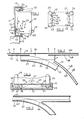
- the vehicle 10 is cantilever supported on a track 11.
- the track 11 is an elevated track extending between spaced vertical support posts 12.
- the track 11 comprises a vertical wall portion 13 connecting a lower horizontal flange 14 and an upper horizontal flange 15.
- the lower flange 14 is formed at its extremity with an upstanding side wall 16 and the upper flange 15 is formed at its extremity with a depending wall 17.
- the lower portion of the main wall 13 of the track defines a further vertical side wall 18.
- the vehicle 10 is provided at the bottom with bottom support wheels 19, 20, 21 and 22 rotatable about horizontal axes, only the rear wheels 19 and 20 being seen in Figure 1.
- the wheels 19, 20, 21 and 22 are provided with resiliently flexible tyres, for example pneumatic rubber tyres.
- the vehicle 10 travels around the elevated track 11 cantilevered from its left hand side.
- One or more of the bottom support wheels may be power driven to drive the vehicle around the track, or any other suitable form of drive may be employed.
- the junction is shown diagrammatically in plan view in Figure 3, which shows the bottom vertical side wall portion 18 of the track, the lower horizontal flange 14 and the short vertical side wall 16.
- the upper flange 15 and upper side wall 17 are not shown.
- the corresponding parts of the track on the two alternative routes out of the junction are indicated at 14a, 16a, 18a and 14b, 16b and 18b respectively.
- the lower horizontal flanges 14, 14a and 14b of the different portions of the track are all co-planar with, and lead onto, a substantially flat continuous horizontal surface 34.
- the left hand side of the surface 34 (looking in the direction of travel from left to right in Figure 3) is bounded by the side wall portions 18 and 18a, whereas the right hand side is bounded by a vertical guide wall 35 which is curved to correspond to the curved path leading from the flange portion 14 to the flange portion 14b.
- a portion of the upstanding side wall 16 on the track is removed to provide an elongate gap 36 extending across the central portion of the horizontal surface 34.
- the horizontal surface 34 is formed with two guideways 37, 38 recessed into the surface thereof, which guideways extend across the junction.
- One of the guideways, 37 is straight and is parallel to the portion of the track provided by the flanges 14, 14a.
- the other guideway, 38 is curved and follows the curvature, across the junction, between the flanges 14, 14b.
- rocker arms 39, 40 which are pivotally mounted on the vehicle to swing about a central longitudinal horizontal axis, indicated at 41.
- the rocker arms carry at their ends respectively steel flanged wheels 42, 43 which act as followers for cooperation with the recessed guideways 38 and 37 respectively.
- the follower system 39-43 is duplicated at the forward end of the vehicle.
- the vehicle As the vehicle approaches the junction, for example in the position indicated at A, the vehicle is cantilevered from the left, as shown in Figure 1.
- the outer bottom support wheels 20 and 22 of the vehicle run onto the horizontal track surface 34 of the junction, which may be slightly ramped upwards at position B to facilitate this.
- the vehicle then is entirely bottom supported and the load on the upper cantilever support wheels 25, 26 is removed.
- the lower part of the vehicle when in this position is shown, enlarged, in Figure 4. It will be seen that, in this position, the left hand lower guide wheels 27 engage the left hand wall portion 18 of the main wall of the track whereas the right hand guide wheels 28 engage the boundary wall 35 on the horizontal surface 34.
- the rocker arms 39 are swung downwardly to bring the left hand follower wheels 42 into engagement with the recessed guideways 38.
- the right hand follower wheels 43 are raised out of engagement with the guideway 37, as shown in Figure 4.
- the vehicle then continues to the position indicated at C.
- the left hand bottom support wheels 19 and 21 reach the gap 36 in the upstanding flange 16 and the upper guide wheels 25, 26 meet a corresponding gap in the depending side wall 17 at the upper part of the track.
- the bottom supported vehicle is thus free to follow the curved path of the recessed guideway 38, being guided along that guideway by engagement of the guideway by the follower wheels 42.
- the lower guide wheels 28 remain in engagement with the wall 35, but as the vehicle moves across the surface 34 the left hand lower guide wheels 27 are brought out of engagement with the wall portion 18.
- the left hand bottom support wheels 19, 21 engage the lower flange 14b, between the outer wall portion 18b and the upstanding wall 16b.
- the upper guide wheels 25 and 26 enter between the upper side wall 17 and the upper part of the main wall 13 of the track.
- the other rocker arms 40 are swung downwardly to bring the right hand guide wheels 43 into engagement with the straight recessed guideway 37.
- the cooperation of the wheels 43 with the guideway 37 then cause the vehicle to be guided straight ahead so that the left hand lower guide wheels 27 remain in engagement with the wall portion 18 and the right hand lower guide wheels 28 are brought out of engagement with the wall 35.
- rocker mounted guide wheels cooperating with recessed guideways may also be used to guide the vehicle if it is required that it should temporarily leave the cantilever track altogether and travel over a greater length of flat surface on bottom support.
- the vehicle may even travel over ordinary roads provided the roads are formed with suitable recessed guideways.
- it may be advantageous to arrange the rocker arms so that all four guide wheels can be lowered simultaneously for engagement with two parallel recessed guideways to provide more stable guidance to the vehicle.
- the recessed guideways 37 and 38 are illustrated as being simple grooves in the surface 34, but it will be appreciated that they might instead be in the form of recessed spaced rails, similar to tramlines. It will be appreciated that certain fundamental problems of using tramlines for guidance are overcome in the present construction.
- the downward loading upon the steel wheels 42 and 43 is light, because they do not have to support the weight of the vehicle, the weight being supported on the pneumatic tyred wheels 19, 20, 21 and 22.
- the arrangement of the wheels 42, 43 on the rocker arms is such that they can sustain heavy horizontal transverse loads, if necessary, as previously described.
- the recessed guideways 37 and 38, and the guide wheels 42 and 43 are dispensed with. Since, at the junction, the normally cantilever supported vehicle is bottom supported, it becomes possible to steer the vehicle through the junction, either automatically or manually, by providing for certain of the bottom support wheels, usually the front wheels 21 and 22, to be steerable. Thus, when position B is reached in Figure 3, the front wheels of the vehicle may be steered to the right so as to bias the vehicle to the right and thus to maintain the right hand guide wheels 28 in engagement with the wall 35. The vehicle will thus automatically follow the curved path to the right until the cantilever support wheels again engage the track at position F. Similarly, in order for the vehicle to continue straight ahead, the steerable wheels will be turned to the left so as to bias the vehicle to the left and maintain the left hand guide wheels 27 in engagement with the wall part 18.
- Figure 5 shows a divergent junction on a track where the vehicle is constantly bottom supported throughout the track.
- the vehicle is provided only with the bottom support wheels 19, 20, 21 and 22 and the lower guide wheels 27 and 28.
- the bottom support wheels run on the flat lower surface 40 of the track and the guide wheels 27 engage upstanding side walls 41 and 42 respectively.
- the flat substantially continuous horizontal surface of the track is formed with recessed guideways 43, 44 which correspond to the guideways 37 and 38 respectively of Figure 3.
- the vehicle is provided with rocker and guide wheel systems corresponding to the system 39-43 of Figures 2 and 4 and the vehicle is guided to a selected route out of the junction by lowering the appropriate guide wheel as previously described.
Landscapes
- Engineering & Computer Science (AREA)
- Mechanical Engineering (AREA)
- Transportation (AREA)
- Architecture (AREA)
- Civil Engineering (AREA)
- Structural Engineering (AREA)
- Platform Screen Doors And Railroad Systems (AREA)
Applications Claiming Priority (2)
| Application Number | Priority Date | Filing Date | Title |
|---|---|---|---|
| GB878706741A GB8706741D0 (en) | 1987-03-20 | 1987-03-20 | Hire cars & cantilevering |
| GB8706741 | 1987-03-20 |
Publications (2)
| Publication Number | Publication Date |
|---|---|
| EP0284316A2 true EP0284316A2 (fr) | 1988-09-28 |
| EP0284316A3 EP0284316A3 (fr) | 1989-03-29 |
Family
ID=10614371
Family Applications (1)
| Application Number | Title | Priority Date | Filing Date |
|---|---|---|---|
| EP88302433A Withdrawn EP0284316A3 (fr) | 1987-03-20 | 1988-03-21 | Système de transport ferroviaire |
Country Status (2)
| Country | Link |
|---|---|
| EP (1) | EP0284316A3 (fr) |
| GB (1) | GB8706741D0 (fr) |
Cited By (8)
| Publication number | Priority date | Publication date | Assignee | Title |
|---|---|---|---|---|
| FR2637860A1 (fr) * | 1988-10-17 | 1990-04-20 | Adl Automation | Machine de transfert libre, a chariots independants et motorises, et a module d'orientation de tels chariots |
| EP0365446A1 (fr) * | 1988-10-17 | 1990-04-25 | Adl Automation Societe A Responsabilite Limitee : | Machine de transfert libre, à chariots indépendants et motorisés, et à module d'orientation de tels chariots |
| RU2153430C1 (ru) * | 1999-12-29 | 2000-07-27 | Государственное предприятие "Московский институт теплотехники" | Эстакадная транспортная система |
| CN102320302A (zh) * | 2011-04-28 | 2012-01-18 | 北京建筑工程学院 | 一种高速移动通讯监控运载系统 |
| CN102648318A (zh) * | 2009-10-02 | 2012-08-22 | 罗尔工业公司 | 包括两个相继路面预制元件的面对面的两个横向端部的横向接合装置及其连接系统 |
| CN110735368A (zh) * | 2019-10-23 | 2020-01-31 | 上海宝冶集团有限公司 | 一种设备轨道安装系统及方法 |
| WO2022101146A1 (fr) * | 2020-11-11 | 2022-05-19 | Urban.MASS Ltd | Améliorations apportées à des véhicules pouvant fonctionner à la fois sur le sol et sur un support en porte-à-faux et à leurs chenilles |
| WO2024188904A1 (fr) * | 2023-03-10 | 2024-09-19 | Urban.MASS Ltd | Véhicules capables de fonctionner sur des supports en porte-à-faux, des voies de guidage et des voies de circulation classiques |
Family Cites Families (4)
| Publication number | Priority date | Publication date | Assignee | Title |
|---|---|---|---|---|
| US3451351A (en) * | 1968-06-14 | 1969-06-24 | Alan B Hawes | Monorail switching system |
| DE2163825A1 (de) * | 1971-12-17 | 1973-06-20 | Monocab Inc | Umleitungsvorrichtung fuer schwebebahnen |
| DE2162738A1 (de) * | 1971-12-17 | 1973-06-20 | Otto Prof Dr Ing Lutz | Laufwerkanordnung fuer sich selbst steuernde fahrzeuge |
| DE2627523C2 (de) * | 1976-06-18 | 1985-04-04 | Daimler-Benz Ag, 7000 Stuttgart | Verkehrssystem mit Fahrrinne und darin mechanisch quergeführten straßengängigen Fahrzeugen |
-
1987
- 1987-03-20 GB GB878706741A patent/GB8706741D0/en active Pending
-
1988
- 1988-03-21 EP EP88302433A patent/EP0284316A3/fr not_active Withdrawn
Cited By (10)
| Publication number | Priority date | Publication date | Assignee | Title |
|---|---|---|---|---|
| FR2637860A1 (fr) * | 1988-10-17 | 1990-04-20 | Adl Automation | Machine de transfert libre, a chariots independants et motorises, et a module d'orientation de tels chariots |
| EP0365446A1 (fr) * | 1988-10-17 | 1990-04-25 | Adl Automation Societe A Responsabilite Limitee : | Machine de transfert libre, à chariots indépendants et motorisés, et à module d'orientation de tels chariots |
| US5044283A (en) * | 1988-10-17 | 1991-09-03 | Adl Automation | Free transfer machine, with independent, motorized carriages and with module for orientation of such carriages |
| RU2153430C1 (ru) * | 1999-12-29 | 2000-07-27 | Государственное предприятие "Московский институт теплотехники" | Эстакадная транспортная система |
| CN102648318A (zh) * | 2009-10-02 | 2012-08-22 | 罗尔工业公司 | 包括两个相继路面预制元件的面对面的两个横向端部的横向接合装置及其连接系统 |
| CN102648318B (zh) * | 2009-10-02 | 2014-07-23 | 罗尔工业公司 | 两个预制元件之间的接合装置及其利用和组装方法 |
| CN102320302A (zh) * | 2011-04-28 | 2012-01-18 | 北京建筑工程学院 | 一种高速移动通讯监控运载系统 |
| CN110735368A (zh) * | 2019-10-23 | 2020-01-31 | 上海宝冶集团有限公司 | 一种设备轨道安装系统及方法 |
| WO2022101146A1 (fr) * | 2020-11-11 | 2022-05-19 | Urban.MASS Ltd | Améliorations apportées à des véhicules pouvant fonctionner à la fois sur le sol et sur un support en porte-à-faux et à leurs chenilles |
| WO2024188904A1 (fr) * | 2023-03-10 | 2024-09-19 | Urban.MASS Ltd | Véhicules capables de fonctionner sur des supports en porte-à-faux, des voies de guidage et des voies de circulation classiques |
Also Published As
| Publication number | Publication date |
|---|---|
| GB8706741D0 (en) | 1987-04-23 |
| EP0284316A3 (fr) | 1989-03-29 |
Similar Documents
| Publication | Publication Date | Title |
|---|---|---|
| US3628462A (en) | Vehicle switching apparatus | |
| KR960008199B1 (ko) | 철도차량의 차륜 간격변경 방법과, 차륜간격 가변성 차대 및 그에 따른 지상설비 | |
| US4821845A (en) | Traversing elevator | |
| US6012396A (en) | Electric rail transportation system, vehicle, and rail used in the transportation system | |
| US4620486A (en) | Rail-guard transportation system | |
| US3830163A (en) | Monorail vehicle switching arrangement | |
| US4027596A (en) | Rapid transit system | |
| SU1366048A3 (ru) | Транспортная система | |
| US4794866A (en) | Linear motor driven railway car | |
| US2825291A (en) | Overhead urban railway | |
| CA1206808A (fr) | Train pour la pose de voies neuves | |
| US5450797A (en) | Transporting system with a floor conveyor device guided on guide rails | |
| US6253685B1 (en) | Guide rail for automatic controlled road vehicles | |
| US4532385A (en) | Load transporting device and electric supply track therefor | |
| US3788233A (en) | Guided transportation system | |
| US4658731A (en) | Apparatus for transporting goods to and from shelves having dual function guide rollers | |
| JP2002037059A (ja) | 分岐を備えた有軌道台車システム | |
| US5829356A (en) | Switching device for use in suspended conveyors | |
| US6393993B1 (en) | Transit switching system for monorail vehicles | |
| US2162351A (en) | Combined road and rail vehicle and track system therefor | |
| GB2025870A (en) | Double-track Overhead Conveyors | |
| US3916798A (en) | Guiding system for a computer controlled vehicle | |
| US4152992A (en) | Track switching arrangement | |
| US4032095A (en) | Central guide system for vehicles | |
| US4721043A (en) | Track guided transportation system |
Legal Events
| Date | Code | Title | Description |
|---|---|---|---|
| PUAI | Public reference made under article 153(3) epc to a published international application that has entered the european phase |
Free format text: ORIGINAL CODE: 0009012 |
|
| AK | Designated contracting states |
Kind code of ref document: A2 Designated state(s): BE CH DE ES FR GB IT LI NL |
|
| PUAL | Search report despatched |
Free format text: ORIGINAL CODE: 0009013 |
|
| AK | Designated contracting states |
Kind code of ref document: A3 Designated state(s): BE CH DE ES FR GB IT LI NL |
|
| 17P | Request for examination filed |
Effective date: 19890505 |
|
| 17Q | First examination report despatched |
Effective date: 19900514 |
|
| STAA | Information on the status of an ep patent application or granted ep patent |
Free format text: STATUS: THE APPLICATION IS DEEMED TO BE WITHDRAWN |
|
| 18D | Application deemed to be withdrawn |
Effective date: 19900924 |