EP0284512B1 - Speisevorrichtung durch Schwerkraft für eine Farbspritzpistole - Google Patents
Speisevorrichtung durch Schwerkraft für eine Farbspritzpistole Download PDFInfo
- Publication number
- EP0284512B1 EP0284512B1 EP19880400714 EP88400714A EP0284512B1 EP 0284512 B1 EP0284512 B1 EP 0284512B1 EP 19880400714 EP19880400714 EP 19880400714 EP 88400714 A EP88400714 A EP 88400714A EP 0284512 B1 EP0284512 B1 EP 0284512B1
- Authority
- EP
- European Patent Office
- Prior art keywords
- gun
- connector
- paint
- coupling element
- reservoir
- Prior art date
- Legal status (The legal status is an assumption and is not a legal conclusion. Google has not performed a legal analysis and makes no representation as to the accuracy of the status listed.)
- Expired - Lifetime
Links
- 239000003973 paint Substances 0.000 title claims description 26
- 239000007921 spray Substances 0.000 title claims description 19
- 230000005484 gravity Effects 0.000 title claims description 13
- 230000008878 coupling Effects 0.000 claims 4
- 238000010168 coupling process Methods 0.000 claims 4
- 238000005859 coupling reaction Methods 0.000 claims 4
- 238000007789 sealing Methods 0.000 claims 2
- 230000000284 resting effect Effects 0.000 claims 1
- 238000010422 painting Methods 0.000 description 5
- 239000000463 material Substances 0.000 description 3
- 238000005507 spraying Methods 0.000 description 3
- 238000007792 addition Methods 0.000 description 1
- 239000012530 fluid Substances 0.000 description 1
- 230000004048 modification Effects 0.000 description 1
- 238000012986 modification Methods 0.000 description 1
- 230000002093 peripheral effect Effects 0.000 description 1
- 239000000126 substance Substances 0.000 description 1
- 238000011144 upstream manufacturing Methods 0.000 description 1
Images

Classifications
-
- B—PERFORMING OPERATIONS; TRANSPORTING
- B05—SPRAYING OR ATOMISING IN GENERAL; APPLYING FLUENT MATERIALS TO SURFACES, IN GENERAL
- B05B—SPRAYING APPARATUS; ATOMISING APPARATUS; NOZZLES
- B05B7/00—Spraying apparatus for discharge of liquids or other fluent materials from two or more sources, e.g. of liquid and air, of powder and gas
- B05B7/24—Spraying apparatus for discharge of liquids or other fluent materials from two or more sources, e.g. of liquid and air, of powder and gas with means, e.g. a container, for supplying liquid or other fluent material to a discharge device
- B05B7/2402—Apparatus to be carried on or by a person, e.g. by hand; Apparatus comprising containers fixed to the discharge device
- B05B7/2405—Apparatus to be carried on or by a person, e.g. by hand; Apparatus comprising containers fixed to the discharge device using an atomising fluid as carrying fluid for feeding, e.g. by suction or pressure, a carried liquid from the container to the nozzle
- B05B7/2408—Apparatus to be carried on or by a person, e.g. by hand; Apparatus comprising containers fixed to the discharge device using an atomising fluid as carrying fluid for feeding, e.g. by suction or pressure, a carried liquid from the container to the nozzle characterised by the container or its attachment means to the spray apparatus
- B05B7/2413—Apparatus to be carried on or by a person, e.g. by hand; Apparatus comprising containers fixed to the discharge device using an atomising fluid as carrying fluid for feeding, e.g. by suction or pressure, a carried liquid from the container to the nozzle characterised by the container or its attachment means to the spray apparatus with means for changing the position or the orientation of the container relative to the spray apparatus
-
- B—PERFORMING OPERATIONS; TRANSPORTING
- B05—SPRAYING OR ATOMISING IN GENERAL; APPLYING FLUENT MATERIALS TO SURFACES, IN GENERAL
- B05B—SPRAYING APPARATUS; ATOMISING APPARATUS; NOZZLES
- B05B7/00—Spraying apparatus for discharge of liquids or other fluent materials from two or more sources, e.g. of liquid and air, of powder and gas
- B05B7/24—Spraying apparatus for discharge of liquids or other fluent materials from two or more sources, e.g. of liquid and air, of powder and gas with means, e.g. a container, for supplying liquid or other fluent material to a discharge device
- B05B7/2402—Apparatus to be carried on or by a person, e.g. by hand; Apparatus comprising containers fixed to the discharge device
- B05B7/2478—Gun with a container which, in normal use, is located above the gun
Definitions
- the invention relates to paint or similar material spray guns and, more particularly, it relates to the system for supplying such guns with paint or other material to be sprayed.
- Spray guns of this type currently known are generally supplied with paint from a reservoir cup which is disposed under the spray gun while being connected to the spray orifice thereof by a duct oriented perpendicular to the axis of the spray gun. .
- This arrangement of the paint reservoir cup sometimes proves to be impractical when the configuration of the parts to be painted requires orienting the spray gun in certain positions.
- Document FR-A-2363375 discloses a compressed air gun for spraying fluid substances such as paint, which in its embodiment of FIGS. 2 and 3, is equipped with a gravity feed device .
- the paint container is connected laterally by means of a sleeve which is mounted for free rotation on a hollow shaft opening into the gun.
- An annular chamber is formed between the sleeve and the hollow shaft, and communicates with an internal channel of the latter.
- the object of the present invention is to remedy the drawbacks presented by known supply devices for spray guns for painting or the like, and for this purpose it proposes a gravity supply device which, while being of a great simplicity and low cost, ensures a perfect supply of paint to the gun regardless of the inclination given to it, with an excellent seal without the use of seals and which allows the gun to be perfectly balanced in the hand regardless of its position of use.
- the gun is supplied from a connector which projects laterally with respect to the body of the gun, being oriented in a direction practically perpendicular to the plane of the latter.
- This hollow connection engages the hollow interior part of a connecting piece into which opens, via a rigid conduit, the open lower end of the bucket forming a paint reservoir.
- the body of the fitting On its intermediate part, has a groove profile with radial openings allowing the paint to flow. inside the fitting.
- Conical surfaces on the opposite faces of the connecting piece are designed which, in the device's position of use, are clamped against parts of conjugated conical shape presented on the one hand by one end of the body of the fitting and, on the other hand, by a blind clamping nut screwing onto the threaded free end of the fitting.
- the device thus achieves, by tightening the nut, an excellent seal that does not require the use of seals and that it allows, depending on the position of use of the gun, to adjust the inclination of the bucket by pivot around the fitting, and fix the bucket in the position thus chosen, so as to always allow a good flow by gravity of the paint out of the bucket and a good balancing of the device in the hand of the user.
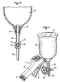
- a spray gun for spraying paint with at 2 a compressed air inlet pipe extending the butt 3, at 4 the spray nozzle and at 5 the control trigger.
- a tubular connector 6 projects from the front part of the gun 1, the inner end 7 of this connector opening into a supply chamber (not shown in the drawing) located upstream of the spray nozzle 4.
- the body of the connector 6 has, from its inner end 7, a portion 8 of larger diameter continuing with a conical portion 9 itself extended by a cylindrical portion 10.
- the cylindrical portion 10 has a groove peripheral 11 radially pierced with four openings 12 communicating with the interior of the fitting. The body of the latter ends outwards by a threaded part 13.
- the bucket 14, forming a paint reservoir is made of a rigid plastic material and has a cylindrical body continuing at its base by a conical part in the form of a funnel.
- the bucket 14 is closed at its upper part by a screwable cover 15 and it has at its lower end an outlet orifice 16 which is screwed into the upper part 17 of a rigid conduit 18 having at its intermediate part a connecting piece 19.
- the part 19 has, oriented perpendicular to the axis of the rod 18, a bore 20 of circular section at the upper part of which opens, through an opening 21, the end of the hollow rod 18.
- the part 19 has a conical bearing surface respectively 22, 23 and it continues, at its lower part, with a support leg 24.
- the part 19 is designed to receive, in its bore 20, the body of the connector 6, the conical surface 22 of the part 19 coming to apply in sealed manner against the conjugate conical part 9 of the connector 6.
- a cap nut 25, having at its open end a conical part 26 is screwed onto the threaded end 13 of the body of the connector 6 so that this conical part 26 comes engage the conjugate conical bearing surface 23 of the connecting piece 19.
- the lengths of the connector 6 and of the conduit 18 are provided such that the cup 14 projects laterally above the gun 1 while being disposed in a vertical plane very close to it so as not to unbalance the gun in use .
- the mounting of the cup 14 on the connector 6 allows, before tightening the nut 25, to orient the inclination of the cup at will in a plane parallel to that of the gun, so, according to the position of use gun, on the one hand to permanently ensure a good supply of paint and, on the other hand, good balancing of the gun in the hand of the user.
- the bucket 14 is then immobilized in this position by tightening the nut 25.
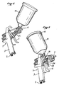
- the gun has been shown in a position suitable for painting a horizontal surface, the bucket 14 then being inclined widely backwards allowing good flow of the paint by gravity out of the bucket and good balancing. of the spray gun whereas, in this position, a traditional gravity feed spray gun would be unbalanced forwards by the weight of the paint contained in the bucket.
- the spray gun is shown in a position suitable for painting a vertical surface, the cup 14 then being in an intermediate position slightly inclined towards the rear, and in FIG. 6, the spray gun 1 is shown in a suitable position. to paint from below a surface inside, the bucket 14 then being in a very forward tilted position.
- the position shown in FIG. 1 also corresponds to a position for laying the gun when it is not in use and it can then be seen that the cup 14 can advantageously be oriented so that the end of the leg d 'support 24 engages the support surface by constituting a stand which ensures stable positioning of the gun.
Landscapes
- Nozzles (AREA)
Claims (3)
Applications Claiming Priority (2)
| Application Number | Priority Date | Filing Date | Title |
|---|---|---|---|
| FR8704048A FR2612810B1 (fr) | 1987-03-24 | 1987-03-24 | Dispositif d'alimentation par gravite pour pistolet de pulverisation de peinture ou de produit analogue |
| FR8704048 | 1987-03-24 |
Publications (2)
| Publication Number | Publication Date |
|---|---|
| EP0284512A1 EP0284512A1 (de) | 1988-09-28 |
| EP0284512B1 true EP0284512B1 (de) | 1991-08-07 |
Family
ID=9349349
Family Applications (1)
| Application Number | Title | Priority Date | Filing Date |
|---|---|---|---|
| EP19880400714 Expired - Lifetime EP0284512B1 (de) | 1987-03-24 | 1988-03-24 | Speisevorrichtung durch Schwerkraft für eine Farbspritzpistole |
Country Status (3)
| Country | Link |
|---|---|
| EP (1) | EP0284512B1 (de) |
| DE (1) | DE3864047D1 (de) |
| FR (1) | FR2612810B1 (de) |
Families Citing this family (2)
| Publication number | Priority date | Publication date | Assignee | Title |
|---|---|---|---|---|
| DE4416939A1 (de) * | 1994-05-13 | 1995-11-16 | Bruno Jesswein Kunststofftechn | Spritzpistole |
| FR2784314B1 (fr) * | 1998-10-09 | 2001-09-21 | Patrick Martinez | Dispositif d'alimentation par gravite d'un pulverisateur notamment de peinture |
Family Cites Families (4)
| Publication number | Priority date | Publication date | Assignee | Title |
|---|---|---|---|---|
| DE325593C (de) * | 1918-11-17 | 1920-09-15 | Karl Schwarz | Rohrgelenk |
| US3219366A (en) * | 1962-02-20 | 1965-11-23 | Imp Eastman Corp | Reinforced fluid control fitting |
| FR1337432A (fr) * | 1962-08-01 | 1963-09-13 | Pistolet pulvérisateur universel | |
| FR2363375A1 (fr) * | 1976-09-01 | 1978-03-31 | Boulot Annic | Pistolet a air comprime pour la projection de substances fluides ou finement divisees dans une direction variable et en proportions variables |
-
1987
- 1987-03-24 FR FR8704048A patent/FR2612810B1/fr not_active Expired
-
1988
- 1988-03-24 DE DE8888400714T patent/DE3864047D1/de not_active Expired - Fee Related
- 1988-03-24 EP EP19880400714 patent/EP0284512B1/de not_active Expired - Lifetime
Also Published As
| Publication number | Publication date |
|---|---|
| DE3864047D1 (de) | 1991-09-12 |
| FR2612810A1 (fr) | 1988-09-30 |
| EP0284512A1 (de) | 1988-09-28 |
| FR2612810B1 (fr) | 1989-06-16 |
Similar Documents
| Publication | Publication Date | Title |
|---|---|---|
| CA2332472C (fr) | Organe de prehension orientable pour le transport ou l'usinage d'une piece de forme quelconque | |
| FR2900583A1 (fr) | Pulverisateur de texture | |
| FR2576225A1 (fr) | Pulverisateur actionne manuellement, avec reglage de la configuration du liquide projete | |
| FR2481955A1 (fr) | Appareil de pulverisation de liquide a disque d'atomisation | |
| FR2669560A1 (fr) | Pulverisateur a main, monte sur un conteneur a col incline. | |
| FR2526681A1 (fr) | Appareil rotatif d'arrosage d'eau | |
| FR2567752A3 (fr) | Gicleur pour hydro-massage | |
| EP3827902A1 (de) | Kit für sprühpistole, anwendungsverfahren und entsprechende pistole | |
| FR2543024A1 (fr) | Dispositif distributeur sous la forme d'un pistolet de calfatage | |
| CH663964A5 (fr) | Appareil d'alimentation en poudre pour dispositif de pulverisation thermique. | |
| FR2624408A1 (fr) | Dispositif de nettoyage de l'interieur d'un recipient avec un jet de liquide | |
| EP0284512A1 (de) | Speisevorrichtung durch Schwerkraft für eine Farbspritzpistole | |
| EP2291633B1 (de) | Vorrichtung zur auflösung einer probe | |
| FR2600914A1 (fr) | Pistolet pulverisateur pour liquides, en particulier peintures | |
| FR2792620A1 (fr) | Support de poche souple et distributeur comprenant un tel support | |
| EP1867396B1 (de) | Lackierspritzpistole mit Druckdose | |
| FR2587631A1 (fr) | Dispositif de reglage du debit de l'air dans un pistolet a peinture | |
| WO2005005056A1 (fr) | Buse de diffusion de poudre pour un dispositif de poudrage electrostatique a jet oriente | |
| EP0122832A1 (de) | Beschichtungsrolle und eine solche Rolle enthaltende Flüssigkeitsbeschichtungseinrichtung | |
| EP1149633B1 (de) | Zerstäubungsvorrichtung | |
| FR2529102A1 (fr) | Gicleur, en particulier pour phares de vehicules | |
| FR2551318A1 (fr) | Appareil d'arrosage a entrainement par impact | |
| FR2625993A3 (fr) | Buse anti-gouttes pour unite doseuse de conditionnement d'un produit a comportement fluide | |
| FR2540405A3 (fr) | Rampe de pulverisation pour l'agriculture | |
| FR2462360A1 (fr) | Embout de pulverisation a deux elements tournants |
Legal Events
| Date | Code | Title | Description |
|---|---|---|---|
| PUAI | Public reference made under article 153(3) epc to a published international application that has entered the european phase |
Free format text: ORIGINAL CODE: 0009012 |
|
| AK | Designated contracting states |
Kind code of ref document: A1 Designated state(s): DE ES GB IT |
|
| 17P | Request for examination filed |
Effective date: 19881226 |
|
| 17Q | First examination report despatched |
Effective date: 19890825 |
|
| GRAA | (expected) grant |
Free format text: ORIGINAL CODE: 0009210 |
|
| AK | Designated contracting states |
Kind code of ref document: B1 Designated state(s): DE ES GB IT |
|
| PG25 | Lapsed in a contracting state [announced via postgrant information from national office to epo] |
Ref country code: GB Effective date: 19910807 Ref country code: ES Free format text: THE PATENT HAS BEEN ANNULLED BY A DECISION OF A NATIONAL AUTHORITY Effective date: 19910807 |
|
| REF | Corresponds to: |
Ref document number: 3864047 Country of ref document: DE Date of ref document: 19910912 |
|
| ITF | It: translation for a ep patent filed | ||
| GBV | Gb: ep patent (uk) treated as always having been void in accordance with gb section 77(7)/1977 [no translation filed] | ||
| PLBE | No opposition filed within time limit |
Free format text: ORIGINAL CODE: 0009261 |
|
| STAA | Information on the status of an ep patent application or granted ep patent |
Free format text: STATUS: NO OPPOSITION FILED WITHIN TIME LIMIT |
|
| 26N | No opposition filed | ||
| PGFP | Annual fee paid to national office [announced via postgrant information from national office to epo] |
Ref country code: DE Payment date: 19930402 Year of fee payment: 6 |
|
| PG25 | Lapsed in a contracting state [announced via postgrant information from national office to epo] |
Ref country code: DE Effective date: 19941201 |
|
| PG25 | Lapsed in a contracting state [announced via postgrant information from national office to epo] |
Ref country code: IT Free format text: LAPSE BECAUSE OF NON-PAYMENT OF DUE FEES;WARNING: LAPSES OF ITALIAN PATENTS WITH EFFECTIVE DATE BEFORE 2007 MAY HAVE OCCURRED AT ANY TIME BEFORE 2007. THE CORRECT EFFECTIVE DATE MAY BE DIFFERENT FROM THE ONE RECORDED. Effective date: 20050324 |