EP0284531A1 - Bedienungsvorrichtung für ein nach aussen schwenkbares Tür- oder Fensterblatt - Google Patents
Bedienungsvorrichtung für ein nach aussen schwenkbares Tür- oder Fensterblatt Download PDFInfo
- Publication number
- EP0284531A1 EP0284531A1 EP88440016A EP88440016A EP0284531A1 EP 0284531 A1 EP0284531 A1 EP 0284531A1 EP 88440016 A EP88440016 A EP 88440016A EP 88440016 A EP88440016 A EP 88440016A EP 0284531 A1 EP0284531 A1 EP 0284531A1
- Authority
- EP
- European Patent Office
- Prior art keywords
- opening
- carriage
- control device
- rack
- frame
- Prior art date
- Legal status (The legal status is an assumption and is not a legal conclusion. Google has not performed a legal analysis and makes no representation as to the accuracy of the status listed.)
- Granted
Links
- 238000006073 displacement reaction Methods 0.000 claims description 11
- 241000255925 Diptera Species 0.000 description 6
- 239000011521 glass Substances 0.000 description 3
- 238000004519 manufacturing process Methods 0.000 description 3
- 241000238631 Hexapoda Species 0.000 description 2
- 238000004140 cleaning Methods 0.000 description 1
- 230000001419 dependent effect Effects 0.000 description 1
- 230000002542 deteriorative effect Effects 0.000 description 1
- 230000000694 effects Effects 0.000 description 1
Images


Classifications
-
- E—FIXED CONSTRUCTIONS
- E06—DOORS, WINDOWS, SHUTTERS, OR ROLLER BLINDS IN GENERAL; LADDERS
- E06B—FIXED OR MOVABLE CLOSURES FOR OPENINGS IN BUILDINGS, VEHICLES, FENCES OR LIKE ENCLOSURES IN GENERAL, e.g. DOORS, WINDOWS, BLINDS, GATES
- E06B3/00—Window sashes, door leaves, or like elements for closing wall or like openings; Layout of fixed or moving closures, e.g. windows in wall or like openings; Features of rigidly-mounted outer frames relating to the mounting of wing frames
- E06B3/32—Arrangements of wings characterised by the manner of movement; Arrangements of movable wings in openings; Features of wings or frames relating solely to the manner of movement of the wing
-
- E—FIXED CONSTRUCTIONS
- E05—LOCKS; KEYS; WINDOW OR DOOR FITTINGS; SAFES
- E05F—DEVICES FOR MOVING WINGS INTO OPEN OR CLOSED POSITION; CHECKS FOR WINGS; WING FITTINGS NOT OTHERWISE PROVIDED FOR, CONCERNED WITH THE FUNCTIONING OF THE WING
- E05F11/00—Man-operated mechanisms for operating wings, including those which also operate the fastening
- E05F11/02—Man-operated mechanisms for operating wings, including those which also operate the fastening for wings in general, e.g. fanlights
- E05F11/34—Man-operated mechanisms for operating wings, including those which also operate the fastening for wings in general, e.g. fanlights with screw mechanisms
-
- E—FIXED CONSTRUCTIONS
- E05—LOCKS; KEYS; WINDOW OR DOOR FITTINGS; SAFES
- E05D—HINGES OR SUSPENSION DEVICES FOR DOORS, WINDOWS OR WINGS
- E05D15/00—Suspension arrangements for wings
- E05D15/28—Suspension arrangements for wings supported on arms movable in horizontal plane
- E05D15/30—Suspension arrangements for wings supported on arms movable in horizontal plane with pivoted arms and sliding guides
-
- E—FIXED CONSTRUCTIONS
- E05—LOCKS; KEYS; WINDOW OR DOOR FITTINGS; SAFES
- E05F—DEVICES FOR MOVING WINGS INTO OPEN OR CLOSED POSITION; CHECKS FOR WINGS; WING FITTINGS NOT OTHERWISE PROVIDED FOR, CONCERNED WITH THE FUNCTIONING OF THE WING
- E05F11/00—Man-operated mechanisms for operating wings, including those which also operate the fastening
- E05F11/02—Man-operated mechanisms for operating wings, including those which also operate the fastening for wings in general, e.g. fanlights
- E05F11/08—Man-operated mechanisms for operating wings, including those which also operate the fastening for wings in general, e.g. fanlights with longitudinally-moving bars guided, e.g. by pivoted links, in or on the frame
- E05F11/12—Mechanisms by which the bar shifts the wing
- E05F11/16—Mechanisms by which the bar shifts the wing shifting the wing by pivotally-connected members (moving) in a plane perpendicular to the pivot axis of the wing
-
- E—FIXED CONSTRUCTIONS
- E05—LOCKS; KEYS; WINDOW OR DOOR FITTINGS; SAFES
- E05Y—INDEXING SCHEME ASSOCIATED WITH SUBCLASSES E05D AND E05F, RELATING TO CONSTRUCTION ELEMENTS, ELECTRIC CONTROL, POWER SUPPLY, POWER SIGNAL OR TRANSMISSION, USER INTERFACES, MOUNTING OR COUPLING, DETAILS, ACCESSORIES, AUXILIARY OPERATIONS NOT OTHERWISE PROVIDED FOR, APPLICATION THEREOF
- E05Y2900/00—Application of doors, windows, wings or fittings thereof
- E05Y2900/10—Application of doors, windows, wings or fittings thereof for buildings or parts thereof
- E05Y2900/13—Type of wing
- E05Y2900/132—Doors
-
- E—FIXED CONSTRUCTIONS
- E05—LOCKS; KEYS; WINDOW OR DOOR FITTINGS; SAFES
- E05Y—INDEXING SCHEME ASSOCIATED WITH SUBCLASSES E05D AND E05F, RELATING TO CONSTRUCTION ELEMENTS, ELECTRIC CONTROL, POWER SUPPLY, POWER SIGNAL OR TRANSMISSION, USER INTERFACES, MOUNTING OR COUPLING, DETAILS, ACCESSORIES, AUXILIARY OPERATIONS NOT OTHERWISE PROVIDED FOR, APPLICATION THEREOF
- E05Y2900/00—Application of doors, windows, wings or fittings thereof
- E05Y2900/10—Application of doors, windows, wings or fittings thereof for buildings or parts thereof
- E05Y2900/13—Type of wing
- E05Y2900/148—Windows
Definitions
- the invention relates to a device for controlling the opening and closing of an opening pivoting towards the outside of a door or window, comprising an operating handle, such as a crank or the like, arranged on the dormant and actuating frame.
- translation means constituted by a rack inserted in the rebate of the lower edge of said fixed frame.
- This invention will more particularly find its utility for doors or windows opening to the English.
- This type of door or window opening towards the outside has another drawback which essentially resides in the cleaning of the external face of the glazed surface.
- the window is located at a certain height from the ground, it is difficult to access and it turns out to be necessary to provide means making it possible to clean the glass surface of this window from the inside.
- document US-A-4 241 541 discloses a device making it possible to impart, simultaneously, a rotational movement to the opening element around a vertical axis passing through one of its uprights and a movement of translation, parallel to the plane of the frame, of the axis of rotation of this opening.
- the combination of these two movements makes it possible to offset the opening laterally relative to the sleeping frame and thus to obtain a space located on the side of the rotation, which makes it possible to make the external face of the glazed surface accessible.
- the device described in the prior document comprises a crank arranged on the lower cross member of the sleeping frame.
- This crank is connected to a worm whose axis is inclined about thirty degrees from the horizontal, so that the window sill does not interfere with the rotation of the crank.
- the worm gear meshes with a pinion with inclined teeth, mounted in free rotation on a vertical axis.
- On this same vertical axis is pivotally mounted an operating arm comprising, at its end, a roller moving in a rail arranged horizontally and in the lower part of the opening.
- the pinion driven by the worm engages a second pinion mounted in free rotation on an axis integral with the operating arm.
- On this second pinion is fixed a second arm connected by means of a connecting rod to the rear end of the opening.
- the cooperation of the two pinions with inclined teeth allows, on the one hand, to give the operating arm a rotational movement around its axis and, on the other hand, to animate the second arm with a combination of two rotational movements.
- This combination consists of a first rotation of the axis of the second pinion around the axis of the pinion meshed by the worm and a second rotation of the bent arm around the axis of the second pinion.
- This device also includes a compass making it possible to connect the opening leaf to the sleeping frame and the function of which essentially consists in distributing the forces applied, by means of the crank, on the operating arm and on the second arm so as to facilitate this simultaneous rotation and translation of the opening.
- this device has a certain number of drawbacks which lie essentially in the complexity of the mechanism making it possible to control the opening and closing of the opening. This complexity makes this device unreliable.
- the production of certain elements constituting this device for controlling the opening is particularly delicate, which has the consequence of considerably increasing the manufacturing cost. This is the case with the production of pinions, the teeth of which are necessarily inclined due to the worm screw, the axis of which forms, for mechanical and convenience reasons, an angle of about thirty degrees with the horizontal.
- Document US-A-1,724,011 also discloses a device for controlling the opening and closing of a opening pivotally outwards, according to another embodiment.
- this control device comprises an operating handle, disposed on the lower cross member of the fixed frame and actuating a mechanism constituted by a gear system cooperating with a rack. This intervenes on levers controlling, on the one hand, a locking system of the opening and, on the other hand, the rotation of an operating arm connected to the latter.
- said mechanism under the actions of the user on the handle, allows to control the rotation of the opening about an axis substantially offset towards the outside relative to the plane of the frame.
- This document also refers to means making it possible to offset the opening relative to its sleeping frame in order to make possible access to the external glazed surface. However, these means are released manually and cannot be actuated by the opening control device for the opening.
- this known control device also has the disadvantage of being particularly bulky, since it is placed on the window sill, on the internal side of the opening, and not in rebate of the sleeping frame.
- its complexity makes it unreliable and particularly fragile in the event of direct action on the opening, hence the need for a secondary locking system.
- the present invention aims to remedy these drawbacks.
- the invention as characterized in the claims, solves the problem of creating a device for controlling the opening and closing of an opening pivoting outwards from a door or window, comprising an operating handle, such as a crank or the like, disposed on the sleeping frame and actuating translation means constituted by a rack inserted in the rebate of the lower edge of said sleeping frame, these translation means driving rotation means the opening which cooperate with second translation means connected either directly or by means of a secondary arm to the opening, and making it possible to give the latter's axis of rotation a translation parallel to the plane of the sleeping frame.
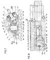
- the door or window 1 to which the control device 2, in accordance with the invention applies, comprises an opening 3 coming to be applied from the outside onto a sleeping frame 4.
- the opening of the opening 3 can only be done by pivoting outwards.
- FIG. 1 represents a window 1 also comprising a mosquito net 5 secured to the sleeping frame 4 and disposed on the internal side of the opening 3.
- control device 2 The purpose of the control device 2 is to be able to cause the opening and closing of the opening 3 from the inner side of the window 1 and without the need to retract the mosquito net 5.
- the availability control device 2 comprises an operating handle 6 represented by a crank in FIG. 1.
- This operating handle 6 is disposed on the sleeping frame 4, approximately in the middle part of the lower edge 7 of said sleeping frame 4.
- This operating handle 6 is connected to a mechanism 8 housed in the rebate 9 of this lower edge 7, or in the absence of a mosquito net, in an appropriate rebate of the opening 3, this mechanism 8 making it possible to actuate the opening 3.
- Said mechanism 8 has the function, on the one hand, to give the opening 3 a pivoting towards the outside around a vertical axis of rotation passing through its rear upright 10 and, on the other hand, to apply to this axis of rotation of the opening 3 a translation parallel to the plane of the fixed frame 4.
- the mechanism 8 of the control device 2 comprises rotation means 11 of the opening 3 driven by translation means 12 actuated by the operating handle 6.
- the mechanism 8, comprising the rotation means 11 and the translation means 12, is disposed in a housing 13 inserted in the rebate 9 of the lower edge 7 of the sleeping frame 4.
- This housing 13 consists of a cover 14 and a base 15 and has a visible longitudinal edge 16 on the internal side of the window 1, in the lower corner 17 formed by the frame 4 and the window sill 18.
- the operating handle 6 In the middle part of the longitudinal edge 16 of the housing 13 is arranged the operating handle 6.
- the latter is integral in rotation with a shaft 19 mounted in free rotation, in the housing 13, by means of bearings 20, 21.
- This shaft 19 is located in a plane perpendicular to the plane of the frame 4 and forms an angle of about thirty degrees with the horizontal, so that the window sill 18 does not hinder the rotation of the operating handle 6.
- the shaft 19 is provided with a drive pinion 22 with straight teeth 23 on which the translation means mesh with each other.
- the latter consist of a rack 24, of rectangular shape, housed in the housing 13, the longitudinal median plane. 25 of the rack 24 being arranged parallel to the plane of the sleeping frame 4.
- This rack 24 has on its longitudinal edge 26 a wing 27 forming an angle of about thirty degrees with the horizontal and having a toothed sector cooperating with the teeth 23 of the drive pinion 22.
- this comprises near its end 28, oriented on the side of the rear upright 10 of the opening 3, a vertical axis 29 located in the longitudinal median plane 25 and the ends 30, 31 of which cooperate with grooves 32, 33 made respectively in the cover 14 and in the base 15 of the housing 13.
- the longitudinal axis of these grooves 32, 33 is arranged horizontally and in the longitudinal median plane 25 of the rack 24.
- the latter is also guided, in its longitudinal displacement, at its end 34, oriented towards the upright 35 of the opening 3, by a roller 36 cooperating with the groove 32 produced in the cover 14 of the housing 13.
- the rotation means 11 of the opening 3. are formed by an operating arm 37, one end 38 of which is pivotally mounted on the vertical axis 29.
- the other end 39 of this arm maneuver 37 is provided with a roller 40 moving in a guide rail 41 disposed horizontally on the inner crosspiece 42 of the frame 43 of the leaf 3.
- This maneuvering arm 37 has, near its end 38, a configuration in shape of "S" 44, which allows to shift laterally the axis of rotation of this maneuvering arm 37 with respect to its longitudinal axis 45.
- the maneuvering arm 37 is disposed under the rack 24.
- the mechanism 8 also has the function of giving the axis of rotation of the opening 3 a translation perpendicular to the plane of the fixed frame 4, so as to take off said opening 3 from the latter.
- the rotation means 11 constituted by the operating arm 37, cooperate with second translation means 46 connected to the opening 3 by a secondary arm 47.
- second translation means 46 connected to the opening 3 by a secondary arm 47.
- the second translation means 46 are constituted by a carriage 48, of approximately rectangular shape, arranged in parallel and under the rack 24. So as to give this carriage 48 a horizontal displacement and in the longitudinal median plane 25 of said rack 24 , said carriage 48 comprises, in its rear part 49, oriented towards the rear upright 10 of the opening 3, an oblong slot 50 cooperating with the vertical axis 29 integral with the rack 24. It should be noted that the operating arm 37 is mounted on the axis 29, between the carriage 48 and the rack 24. This carriage 48 also has at its end 51 an axis 52 which is projecting relative to the underside 53 of said carriage 48 and cooperating with the groove 33 made in the base 15 of the housing 13.
- the carriage 48 is also provided with a toothed sector 54 cooperating with a toothing 55 arranged on the periphery 56 of the end 38 of the operating arm 37.
- This toothing 55 is arranged in the form of an arc of a circle whose center is located on the axis of rotation of the maneuvering arm 37.
- This cooperation of the toothing 55 of said maneuvering arm 37 and of the toothed sector 54 of the carriage 48 has the function of giving the latter a longitudinal displacement in a direction depending on the direction of rotation of the operating arm 37.
- this carriage 48 also plays the role of wedge, in particular in its front part 60 on which the rack 24 rests. It is indeed essential to maintain this the latter in an approximately horizontal position so that the roller 36, disposed at the end 34 of the rack 24, cooperates with the groove 32 of the cover 14.
- the secondary arm 47 is formed by a connecting rod 61, one end 62 of which is integral with the axis 52 disposed at the end 51 of the carriage 48.
- the other end 63 of this connecting rod 61 is connected by a joint 64 at the opening 3 and this near the rear upright 10.
- This connecting rod 61 is slightly bent in a horizontal plane so as to form a wing 65, arranged parallel to the plane of the sleeping frame 4 when the opening 3 is closed and a wing 66 coming to engage in the housing 13 and allowing access to the axis 52.
- the secondary arm 47 is constituted by a slide connected to the carriage 48 and free in translation in a direction perpendicular to the plane of the sleeping frame 4.
- One end of this slide is fixed to the opening 3, near the rear upright 10.
- La liai sound between the carriage 48 and the slide is formed by guide rails or the like arranged perpendicularly to the plane of the fixed frame 4 on the carriage 48, the slide having elements making it possible to cooperate with these guide rails.
- the slider is rectangular in shape and has longitudinal edges engaged in the guide rails disposed on the carriage 48 and the spacing of which is determined as a function of the width of the slider.
- connection between the slide and the opening 3 is necessarily constituted by a hinge 64, so as to allow the opening of the opening 3.
- the lateral edge 67, of the section 68, connecting the end 38 to the "S" shaped portion 44 of the operating arm 37 abuts against the transverse front edge 69 of the toothed sector 54 of the carriage 48.
- the articulation 64 forming the connection between the connecting rod 61 or the slide and the opening 3, is of the removable type.
- the connecting rod 61 or the slide has an end 72 which is placed under a square-shaped element 73 attached to the opening 3 and comprising, in its wing 74, arranged horizontally, an orifice 75.
- the orifices 75 and 76 respectively of the square-shaped element 73 and the end 72, are arranged on the same vertical axis and serve as a passage for a removable fixing element 77.
- the rotation means 11 constituted by the operating arm 37, cooperate with second translation means 146 directly connected to the leaf 3.
- the second translation means 146 are constituted by a carriage 148 of approximately rectangular shape, arranged in parallel and under the rack 24. So as to give this carriage 148 a horizontal displacement and in the longitudinal median plane 25 of said rack 24, said carriage 148 comprises in its rear part 149, oriented towards the rear upright 10 of the opening 3, an oblong opening 150 cooperating with the vertical axis 29 integral with the rack 24. It should be noted that the operating arm 37 is mounted on the axis 29, between the carriage 148 and the rack 24. This carriage 148 also has at its end 151 an axis 152 which is projecting relative to the underside 153 of said carriage 148 and cooperating with the groove 33 made in the base 15 of housing 13.
- the carriage 148 is also provided with a toothed sector 154 cooperating with a toothing 55 arranged on the periphery 56 of the end 38 of the operating arm 37.
- This toothing 55 is arranged in the form of an arc of a circle whose center is located on the axis of rotation of the maneuvering arm 37.
- This cooperation of the teeth 55 of said maneuvering arm 37 and of the toothed sector 154 of the carriage 148 has the function of giving the latter a longitudinal displacement in a direction dependent on the direction of rotation of the operating arm 37.
- this carriage 148 also plays the role of wedge, in particular in its front part 160 on which the rack 24 rests. It is, in fact, essential to maintain the latter in an approximately horizontal position so that the roller 36, disposed at the end 34 of the rack 24, cooperates with the groove 32 of the cover 14.
- connection between the carriage 148 and the opening 3 is constituted by an articulation 64 so as to allow the rotation of the opening 3 around a vertical axis passing through this articulation 64.
- the latter is located most as close as possible to the rear edge 78 of the opening 3, so that the rebate of the sleeping frame 4 does not hinder the rotation of said opening 3.
- the operation of the control device 2 is as follows: By actuating the operating handle 6, there is provided, via the motor pinion 22, a long displacement tudinal to the rack 24. This drives the operating arm 37 which, due to its toothing 55 cooperating with the toothed sector 154 of the carriage 148, pivots about the vertical axis 29. This results in rotation, towards l exterior, opening 3.
- the carriage 148 is caused to move parallel to the plane of the sleeping frame 4, which has the effect of giving the axis of rotation of the opening 3 a translation parallel to said plane of the frame sleeping 4.
- the articulation 64 consists, on the one hand, of an eyelet 172 integral with the carriage 148 and, on the other hand, of a square-shaped element 73 attached to the lower cross member 42 of the frame 43 of the opening 3.
- the eyelet 172 is located at the rear end 180 of the carriage 148 and is projecting relative to the external longitudinal edge 181 of the latter.
- the square-shaped element 73 is provided, in its horizontal wing 74, with an orifice 75 coming to be placed on the same vertical axis and above the orifice 176 of the eyelet 172, the orifices 75 and 176 serving as a passage for a fixing member 77.
- the latter is preferably removable so as to be able to separate the opening 3 of the carriage 148 and thus facilitate access to the external face 70 of the glass surface 71 by rotation of said opening 3 about the axis of the roller 40 integral with the end 39 of the operating arm 37 and moving in the guide rail 41.
- An advantage of the invention is to allow the inversion of the use of each of the elements constituting the mechanism of the control device for one or other of the results obtained and as described, for each of these elements, in the first embodiment.
Landscapes
- Engineering & Computer Science (AREA)
- Mechanical Engineering (AREA)
- Civil Engineering (AREA)
- Structural Engineering (AREA)
- Power-Operated Mechanisms For Wings (AREA)
- Window Of Vehicle (AREA)
- Wing Frames And Configurations (AREA)
- Transmission Devices (AREA)
Priority Applications (1)
| Application Number | Priority Date | Filing Date | Title |
|---|---|---|---|
| AT88440016T ATE58775T1 (de) | 1987-03-12 | 1988-03-10 | Bedienungsvorrichtung fuer ein nach aussen schwenkbares tuer- oder fensterblatt. |
Applications Claiming Priority (2)
| Application Number | Priority Date | Filing Date | Title |
|---|---|---|---|
| FR8703597 | 1987-03-12 | ||
| FR8703597A FR2612239A1 (fr) | 1987-03-12 | 1987-03-12 | Dispositif de commande d'un ouvrant d'une porte ou fenetre a ouverture a l'anglaise |
Publications (2)
| Publication Number | Publication Date |
|---|---|
| EP0284531A1 true EP0284531A1 (de) | 1988-09-28 |
| EP0284531B1 EP0284531B1 (de) | 1990-11-28 |
Family
ID=9349028
Family Applications (1)
| Application Number | Title | Priority Date | Filing Date |
|---|---|---|---|
| EP88440016A Expired - Lifetime EP0284531B1 (de) | 1987-03-12 | 1988-03-10 | Bedienungsvorrichtung für ein nach aussen schwenkbares Tür- oder Fensterblatt |
Country Status (13)
| Country | Link |
|---|---|
| US (1) | US4945679A (de) |
| EP (1) | EP0284531B1 (de) |
| JP (1) | JPS63251588A (de) |
| KR (1) | KR880011436A (de) |
| CN (1) | CN88101257A (de) |
| AT (1) | ATE58775T1 (de) |
| CA (1) | CA1305501C (de) |
| DE (1) | DE3861151D1 (de) |
| ES (1) | ES2019704B3 (de) |
| FR (1) | FR2612239A1 (de) |
| GR (1) | GR3001513T3 (de) |
| HK (1) | HK80891A (de) |
| SG (1) | SG77391G (de) |
Families Citing this family (8)
| Publication number | Priority date | Publication date | Assignee | Title |
|---|---|---|---|---|
| CA2278439C (en) | 1998-07-22 | 2008-03-18 | G-U Hardware, Inc. | Casement window roto-operators |
| US6076304A (en) * | 1999-04-09 | 2000-06-20 | Carrier; Germain | Window opening and closing assembly |
| US6260251B1 (en) * | 1999-08-31 | 2001-07-17 | Andersen Corporation | Unitary profile for window construction |
| US6374544B1 (en) | 2000-09-18 | 2002-04-23 | Frederick Ellis | Window actuator for casement type window |
| US6574921B2 (en) | 2001-06-29 | 2003-06-10 | Eric Zimmermann | Closure operator having a handle that rotates as the closure rotates |
| US7194840B2 (en) * | 2001-06-29 | 2007-03-27 | Eric Zimmermann | Closure operator having a handle that rotates as the closure rotates |
| US6779580B2 (en) * | 2003-01-20 | 2004-08-24 | Marvin Lumber & Cedar Company | Wood interior screen for out-swinging wood window |
| US11230870B2 (en) * | 2018-04-16 | 2022-01-25 | Anthony J. Rotondi | Fenestration hardware system for casement windows |
Citations (5)
| Publication number | Priority date | Publication date | Assignee | Title |
|---|---|---|---|---|
| US1724011A (en) * | 1926-07-02 | 1929-08-13 | Lucien M Flagg | Lock and window adjuster |
| US2585122A (en) * | 1948-09-03 | 1952-02-12 | Rush S Hartman | Closure operating means |
| US2709582A (en) * | 1954-01-14 | 1955-05-31 | Morgan Company | Window |
| US3117351A (en) * | 1961-02-23 | 1964-01-14 | Amerock Corp | Hinge for swinging windows |
| GB2050498A (en) * | 1979-06-08 | 1981-01-07 | Truth Inc | Dual arm operator for a casement-type window |
Family Cites Families (4)
| Publication number | Priority date | Publication date | Assignee | Title |
|---|---|---|---|---|
| US1681798A (en) * | 1927-07-20 | 1928-08-21 | Albert H Carrier | Casement-window attachment |
| US3032330A (en) * | 1957-12-12 | 1962-05-01 | Truth Tool Company | Casement window hinge-lock operator mechanism |
| US4266371A (en) * | 1979-05-23 | 1981-05-12 | Truth Incorporated | Operator for a casement-type window |
| US4305228A (en) * | 1979-05-31 | 1981-12-15 | Truth Incorporated | Operator for a casement-type window |
-
1987
- 1987-03-12 FR FR8703597A patent/FR2612239A1/fr not_active Withdrawn
-
1988
- 1988-03-07 US US07/164,951 patent/US4945679A/en not_active Expired - Fee Related
- 1988-03-10 ES ES88440016T patent/ES2019704B3/es not_active Expired - Lifetime
- 1988-03-10 DE DE8888440016T patent/DE3861151D1/de not_active Expired - Lifetime
- 1988-03-10 AT AT88440016T patent/ATE58775T1/de active
- 1988-03-10 EP EP88440016A patent/EP0284531B1/de not_active Expired - Lifetime
- 1988-03-11 CA CA000561281A patent/CA1305501C/fr not_active Expired - Lifetime
- 1988-03-12 KR KR1019880002663A patent/KR880011436A/ko not_active Withdrawn
- 1988-03-12 JP JP63057395A patent/JPS63251588A/ja active Pending
- 1988-03-12 CN CN198888101257A patent/CN88101257A/zh active Pending
-
1991
- 1991-02-27 GR GR91400240T patent/GR3001513T3/el unknown
- 1991-09-17 SG SG773/91A patent/SG77391G/en unknown
- 1991-10-17 HK HK808/91A patent/HK80891A/xx unknown
Patent Citations (5)
| Publication number | Priority date | Publication date | Assignee | Title |
|---|---|---|---|---|
| US1724011A (en) * | 1926-07-02 | 1929-08-13 | Lucien M Flagg | Lock and window adjuster |
| US2585122A (en) * | 1948-09-03 | 1952-02-12 | Rush S Hartman | Closure operating means |
| US2709582A (en) * | 1954-01-14 | 1955-05-31 | Morgan Company | Window |
| US3117351A (en) * | 1961-02-23 | 1964-01-14 | Amerock Corp | Hinge for swinging windows |
| GB2050498A (en) * | 1979-06-08 | 1981-01-07 | Truth Inc | Dual arm operator for a casement-type window |
Also Published As
| Publication number | Publication date |
|---|---|
| KR880011436A (ko) | 1988-10-28 |
| SG77391G (en) | 1992-03-20 |
| US4945679A (en) | 1990-08-07 |
| CA1305501C (fr) | 1992-07-21 |
| ES2019704B3 (es) | 1991-07-01 |
| DE3861151D1 (de) | 1991-01-10 |
| HK80891A (en) | 1991-10-25 |
| CN88101257A (zh) | 1988-09-21 |
| ATE58775T1 (de) | 1990-12-15 |
| GR3001513T3 (en) | 1992-11-23 |
| JPS63251588A (ja) | 1988-10-19 |
| EP0284531B1 (de) | 1990-11-28 |
| FR2612239A1 (fr) | 1988-09-16 |
Similar Documents
| Publication | Publication Date | Title |
|---|---|---|
| EP0284531B1 (de) | Bedienungsvorrichtung für ein nach aussen schwenkbares Tür- oder Fensterblatt | |
| FR2882588A1 (fr) | Caisson lumineux a raidisseur invisible | |
| EP2694306B2 (de) | Glasdach mit verschiebbarer und schwenkbarer mobiler platte | |
| FR2787498A1 (fr) | Dispositif de securite pour baie vitree a volet mobile | |
| EP0270437B1 (de) | Türverriegelung | |
| EP0352206B1 (de) | nager für Kipp- oder Schwingdachfenster | |
| EP0296088B1 (de) | Bedienungsvorrichtung für einen sich nach aussen öffnenden Flügel einer Tür oder eines Fensters | |
| FR2644507A1 (fr) | Installation comprenant au moins un vantail pivotant autour d'un axe vertical | |
| EP0876946B1 (de) | Türschliesser, damit ausgerüstete Tür und Schienenfahrzeug mit mindestens einer derartigen Vorrichtung und/oder Tür | |
| FR2520038A1 (fr) | Dispositif entrebailleur pour battant de porte ou de fenetre | |
| EP2313593B1 (de) | Tür für das schutzdach eines schwimmbads | |
| FR2807781A1 (fr) | Bati dormant comprenant un ensemble d'entrainement de volets battants | |
| FR2846358A1 (fr) | Dispositif de verrouillage pour baie a deux vantaux ouvrant a la francaise, et baie ainsi equipee | |
| EP1255017B1 (de) | Antriebseinrichtung mit schwimmendem Motor für zwei Mechanismen, insbesondere für Klappladen | |
| FR2621347A1 (fr) | Systeme mecanique de barrage du ou des battants d'une porte, fenetre et similaires par des bacles connectees ensemble de facon appropriee et agissant sur la longueur complete, automatiquement et en synchronisme, quand une de ces bacles est mise en mouvement | |
| FR2632344A1 (fr) | Compas entrebailleur pour fenetre s'ouvrant a l'italienne, a l'australienne, pivotante ou a ouvertures analogues | |
| EP3486408A1 (de) | Fenster- oder türrahmen für eine gebäudeöffnung, die mindestens ein motorisiertes schiebeöffnungselement umfasst, das mit verschlussmitteln ausgestattet ist | |
| FR2929317A1 (fr) | Porte de garage et ensemble comportant une telle porte | |
| FR2556034A1 (fr) | Cremone-serrure a plusieurs points de verrouillage | |
| FR2754304A1 (fr) | Dispositif de commande des lames orientables d'une fenetre du type jalousie | |
| EP0387170B1 (de) | Lager für Dreh- oder Schwingdachfenster | |
| EP2105563B1 (de) | Betätigungssystem eines Schiebeflügels in einer Zarge | |
| EP3619388A1 (de) | Schiebefenster mit wasserdichtungsvorrichtung | |
| FR3130869A1 (fr) | Système de volet en accordéon avec battue automatisée. | |
| FR2761105A1 (fr) | Chassis de fenetre, equipe d'un survitrage |
Legal Events
| Date | Code | Title | Description |
|---|---|---|---|
| PUAI | Public reference made under article 153(3) epc to a published international application that has entered the european phase |
Free format text: ORIGINAL CODE: 0009012 |
|
| AK | Designated contracting states |
Kind code of ref document: A1 Designated state(s): AT BE CH DE ES GB GR IT LI NL SE |
|
| 17P | Request for examination filed |
Effective date: 19881012 |
|
| 17Q | First examination report despatched |
Effective date: 19890918 |
|
| GRAA | (expected) grant |
Free format text: ORIGINAL CODE: 0009210 |
|
| AK | Designated contracting states |
Kind code of ref document: B1 Designated state(s): AT BE CH DE ES GB GR IT LI NL SE |
|
| REF | Corresponds to: |
Ref document number: 58775 Country of ref document: AT Date of ref document: 19901215 Kind code of ref document: T |
|
| REF | Corresponds to: |
Ref document number: 3861151 Country of ref document: DE Date of ref document: 19910110 |
|
| ITF | It: translation for a ep patent filed | ||
| GBT | Gb: translation of ep patent filed (gb section 77(6)(a)/1977) | ||
| PGFP | Annual fee paid to national office [announced via postgrant information from national office to epo] |
Ref country code: GR Payment date: 19910228 Year of fee payment: 4 |
|
| PLBE | No opposition filed within time limit |
Free format text: ORIGINAL CODE: 0009261 |
|
| STAA | Information on the status of an ep patent application or granted ep patent |
Free format text: STATUS: NO OPPOSITION FILED WITHIN TIME LIMIT |
|
| 26N | No opposition filed | ||
| PGFP | Annual fee paid to national office [announced via postgrant information from national office to epo] |
Ref country code: GB Payment date: 19920302 Year of fee payment: 5 |
|
| PGFP | Annual fee paid to national office [announced via postgrant information from national office to epo] |
Ref country code: AT Payment date: 19920310 Year of fee payment: 5 |
|
| PGFP | Annual fee paid to national office [announced via postgrant information from national office to epo] |
Ref country code: CH Payment date: 19920316 Year of fee payment: 5 |
|
| PGFP | Annual fee paid to national office [announced via postgrant information from national office to epo] |
Ref country code: ES Payment date: 19920317 Year of fee payment: 5 |
|
| PGFP | Annual fee paid to national office [announced via postgrant information from national office to epo] |
Ref country code: SE Payment date: 19920319 Year of fee payment: 5 |
|
| ITTA | It: last paid annual fee | ||
| PGFP | Annual fee paid to national office [announced via postgrant information from national office to epo] |
Ref country code: NL Payment date: 19920331 Year of fee payment: 5 |
|
| PGFP | Annual fee paid to national office [announced via postgrant information from national office to epo] |
Ref country code: BE Payment date: 19920512 Year of fee payment: 5 |
|
| PGFP | Annual fee paid to national office [announced via postgrant information from national office to epo] |
Ref country code: DE Payment date: 19920521 Year of fee payment: 5 |
|
| REG | Reference to a national code |
Ref country code: GR Ref legal event code: FG4A Free format text: 3001513 |
|
| PG25 | Lapsed in a contracting state [announced via postgrant information from national office to epo] |
Ref country code: GR Free format text: THE PATENT HAS BEEN ANNULLED BY A DECISION OF A NATIONAL AUTHORITY Effective date: 19920930 |
|
| PG25 | Lapsed in a contracting state [announced via postgrant information from national office to epo] |
Ref country code: GB Effective date: 19930310 Ref country code: AT Effective date: 19930310 |
|
| PG25 | Lapsed in a contracting state [announced via postgrant information from national office to epo] |
Ref country code: SE Effective date: 19930311 Ref country code: ES Free format text: LAPSE BECAUSE OF THE APPLICANT RENOUNCES Effective date: 19930311 |
|
| PG25 | Lapsed in a contracting state [announced via postgrant information from national office to epo] |
Ref country code: LI Effective date: 19930331 Ref country code: CH Effective date: 19930331 Ref country code: BE Effective date: 19930331 |
|
| BERE | Be: lapsed |
Owner name: FERCO INTERNATIONAL USINE DE FERRURES DE BAITMENT Effective date: 19930331 |
|
| PG25 | Lapsed in a contracting state [announced via postgrant information from national office to epo] |
Ref country code: NL Effective date: 19931001 |
|
| GBPC | Gb: european patent ceased through non-payment of renewal fee |
Effective date: 19930310 |
|
| NLV4 | Nl: lapsed or anulled due to non-payment of the annual fee | ||
| REG | Reference to a national code |
Ref country code: CH Ref legal event code: PL |
|
| PG25 | Lapsed in a contracting state [announced via postgrant information from national office to epo] |
Ref country code: DE Effective date: 19931201 |
|
| REG | Reference to a national code |
Ref country code: GR Ref legal event code: MM2A Free format text: 3001513 |
|
| EUG | Se: european patent has lapsed |
Ref document number: 88440016.9 Effective date: 19931008 |
|
| REG | Reference to a national code |
Ref country code: ES Ref legal event code: FD2A Effective date: 19991007 |
|
| PG25 | Lapsed in a contracting state [announced via postgrant information from national office to epo] |
Ref country code: IT Free format text: LAPSE BECAUSE OF NON-PAYMENT OF DUE FEES;WARNING: LAPSES OF ITALIAN PATENTS WITH EFFECTIVE DATE BEFORE 2007 MAY HAVE OCCURRED AT ANY TIME BEFORE 2007. THE CORRECT EFFECTIVE DATE MAY BE DIFFERENT FROM THE ONE RECORDED. Effective date: 20050310 |