EP0284545A1 - Stumpfkappe - Google Patents
Stumpfkappe Download PDFInfo
- Publication number
- EP0284545A1 EP0284545A1 EP88730012A EP88730012A EP0284545A1 EP 0284545 A1 EP0284545 A1 EP 0284545A1 EP 88730012 A EP88730012 A EP 88730012A EP 88730012 A EP88730012 A EP 88730012A EP 0284545 A1 EP0284545 A1 EP 0284545A1
- Authority
- EP
- European Patent Office
- Prior art keywords
- stump
- cap according
- bone
- cap
- thread
- Prior art date
- Legal status (The legal status is an assumption and is not a legal conclusion. Google has not performed a legal analysis and makes no representation as to the accuracy of the status listed.)
- Withdrawn
Links
Images
Classifications
-
- A—HUMAN NECESSITIES
- A61—MEDICAL OR VETERINARY SCIENCE; HYGIENE
- A61F—FILTERS IMPLANTABLE INTO BLOOD VESSELS; PROSTHESES; DEVICES PROVIDING PATENCY TO, OR PREVENTING COLLAPSING OF, TUBULAR STRUCTURES OF THE BODY, e.g. STENTS; ORTHOPAEDIC, NURSING OR CONTRACEPTIVE DEVICES; FOMENTATION; TREATMENT OR PROTECTION OF EYES OR EARS; BANDAGES, DRESSINGS OR ABSORBENT PADS; FIRST-AID KITS
- A61F2/00—Filters implantable into blood vessels; Prostheses, i.e. artificial substitutes or replacements for parts of the body; Appliances for connecting them with the body; Devices providing patency to, or preventing collapsing of, tubular structures of the body, e.g. stents
- A61F2/02—Prostheses implantable into the body
- A61F2/28—Bones
- A61F2/2814—Bone stump caps
-
- A—HUMAN NECESSITIES
- A61—MEDICAL OR VETERINARY SCIENCE; HYGIENE
- A61B—DIAGNOSIS; SURGERY; IDENTIFICATION
- A61B17/00—Surgical instruments, devices or methods
- A61B17/04—Surgical instruments, devices or methods for suturing wounds; Holders or packages for needles or suture materials
- A61B17/06—Needles ; Sutures; Needle-suture combinations; Holders or packages for needles or suture materials
- A61B17/06166—Sutures
-
- A—HUMAN NECESSITIES
- A61—MEDICAL OR VETERINARY SCIENCE; HYGIENE
- A61B—DIAGNOSIS; SURGERY; IDENTIFICATION
- A61B17/00—Surgical instruments, devices or methods
- A61B17/56—Surgical instruments or methods for treatment of bones or joints; Devices specially adapted therefor
- A61B17/58—Surgical instruments or methods for treatment of bones or joints; Devices specially adapted therefor for osteosynthesis, e.g. bone plates, screws or setting implements
- A61B17/68—Internal fixation devices, including fasteners and spinal fixators, even if a part thereof projects from the skin
- A61B17/84—Fasteners therefor or fasteners being internal fixation devices
- A61B17/86—Pins or screws or threaded wires; nuts therefor
- A61B17/8605—Heads, i.e. proximal ends projecting from bone
- A61B17/861—Heads, i.e. proximal ends projecting from bone specially shaped for gripping driver
- A61B17/862—Heads, i.e. proximal ends projecting from bone specially shaped for gripping driver at the periphery of the screw head
-
- A—HUMAN NECESSITIES
- A61—MEDICAL OR VETERINARY SCIENCE; HYGIENE
- A61F—FILTERS IMPLANTABLE INTO BLOOD VESSELS; PROSTHESES; DEVICES PROVIDING PATENCY TO, OR PREVENTING COLLAPSING OF, TUBULAR STRUCTURES OF THE BODY, e.g. STENTS; ORTHOPAEDIC, NURSING OR CONTRACEPTIVE DEVICES; FOMENTATION; TREATMENT OR PROTECTION OF EYES OR EARS; BANDAGES, DRESSINGS OR ABSORBENT PADS; FIRST-AID KITS
- A61F2/00—Filters implantable into blood vessels; Prostheses, i.e. artificial substitutes or replacements for parts of the body; Appliances for connecting them with the body; Devices providing patency to, or preventing collapsing of, tubular structures of the body, e.g. stents
- A61F2/02—Prostheses implantable into the body
- A61F2/30—Joints
- A61F2/30721—Accessories
- A61F2/30744—End caps, e.g. for closing an endoprosthetic cavity
-
- A—HUMAN NECESSITIES
- A61—MEDICAL OR VETERINARY SCIENCE; HYGIENE
- A61F—FILTERS IMPLANTABLE INTO BLOOD VESSELS; PROSTHESES; DEVICES PROVIDING PATENCY TO, OR PREVENTING COLLAPSING OF, TUBULAR STRUCTURES OF THE BODY, e.g. STENTS; ORTHOPAEDIC, NURSING OR CONTRACEPTIVE DEVICES; FOMENTATION; TREATMENT OR PROTECTION OF EYES OR EARS; BANDAGES, DRESSINGS OR ABSORBENT PADS; FIRST-AID KITS
- A61F2/00—Filters implantable into blood vessels; Prostheses, i.e. artificial substitutes or replacements for parts of the body; Appliances for connecting them with the body; Devices providing patency to, or preventing collapsing of, tubular structures of the body, e.g. stents
- A61F2/02—Prostheses implantable into the body
- A61F2/30—Joints
- A61F2002/30001—Additional features of subject-matter classified in A61F2/28, A61F2/30 and subgroups thereof
- A61F2002/30316—The prosthesis having different structural features at different locations within the same prosthesis; Connections between prosthetic parts; Special structural features of bone or joint prostheses not otherwise provided for
- A61F2002/30329—Connections or couplings between prosthetic parts, e.g. between modular parts; Connecting elements
- A61F2002/30476—Connections or couplings between prosthetic parts, e.g. between modular parts; Connecting elements locked by an additional locking mechanism
- A61F2002/30487—Circumferential cooperating grooves and beads on cooperating lateral surfaces of a mainly longitudinal connection
-
- A—HUMAN NECESSITIES
- A61—MEDICAL OR VETERINARY SCIENCE; HYGIENE
- A61F—FILTERS IMPLANTABLE INTO BLOOD VESSELS; PROSTHESES; DEVICES PROVIDING PATENCY TO, OR PREVENTING COLLAPSING OF, TUBULAR STRUCTURES OF THE BODY, e.g. STENTS; ORTHOPAEDIC, NURSING OR CONTRACEPTIVE DEVICES; FOMENTATION; TREATMENT OR PROTECTION OF EYES OR EARS; BANDAGES, DRESSINGS OR ABSORBENT PADS; FIRST-AID KITS
- A61F2/00—Filters implantable into blood vessels; Prostheses, i.e. artificial substitutes or replacements for parts of the body; Appliances for connecting them with the body; Devices providing patency to, or preventing collapsing of, tubular structures of the body, e.g. stents
- A61F2/02—Prostheses implantable into the body
- A61F2/30—Joints
- A61F2002/30001—Additional features of subject-matter classified in A61F2/28, A61F2/30 and subgroups thereof
- A61F2002/30316—The prosthesis having different structural features at different locations within the same prosthesis; Connections between prosthetic parts; Special structural features of bone or joint prostheses not otherwise provided for
- A61F2002/30329—Connections or couplings between prosthetic parts, e.g. between modular parts; Connecting elements
- A61F2002/30476—Connections or couplings between prosthetic parts, e.g. between modular parts; Connecting elements locked by an additional locking mechanism
- A61F2002/305—Snap connection
-
- A—HUMAN NECESSITIES
- A61—MEDICAL OR VETERINARY SCIENCE; HYGIENE
- A61F—FILTERS IMPLANTABLE INTO BLOOD VESSELS; PROSTHESES; DEVICES PROVIDING PATENCY TO, OR PREVENTING COLLAPSING OF, TUBULAR STRUCTURES OF THE BODY, e.g. STENTS; ORTHOPAEDIC, NURSING OR CONTRACEPTIVE DEVICES; FOMENTATION; TREATMENT OR PROTECTION OF EYES OR EARS; BANDAGES, DRESSINGS OR ABSORBENT PADS; FIRST-AID KITS
- A61F2/00—Filters implantable into blood vessels; Prostheses, i.e. artificial substitutes or replacements for parts of the body; Appliances for connecting them with the body; Devices providing patency to, or preventing collapsing of, tubular structures of the body, e.g. stents
- A61F2/02—Prostheses implantable into the body
- A61F2/30—Joints
- A61F2002/30001—Additional features of subject-matter classified in A61F2/28, A61F2/30 and subgroups thereof
- A61F2002/30316—The prosthesis having different structural features at different locations within the same prosthesis; Connections between prosthetic parts; Special structural features of bone or joint prostheses not otherwise provided for
- A61F2002/30535—Special structural features of bone or joint prostheses not otherwise provided for
- A61F2002/30589—Sealing means
-
- A—HUMAN NECESSITIES
- A61—MEDICAL OR VETERINARY SCIENCE; HYGIENE
- A61F—FILTERS IMPLANTABLE INTO BLOOD VESSELS; PROSTHESES; DEVICES PROVIDING PATENCY TO, OR PREVENTING COLLAPSING OF, TUBULAR STRUCTURES OF THE BODY, e.g. STENTS; ORTHOPAEDIC, NURSING OR CONTRACEPTIVE DEVICES; FOMENTATION; TREATMENT OR PROTECTION OF EYES OR EARS; BANDAGES, DRESSINGS OR ABSORBENT PADS; FIRST-AID KITS
- A61F2/00—Filters implantable into blood vessels; Prostheses, i.e. artificial substitutes or replacements for parts of the body; Appliances for connecting them with the body; Devices providing patency to, or preventing collapsing of, tubular structures of the body, e.g. stents
- A61F2/02—Prostheses implantable into the body
- A61F2/30—Joints
- A61F2002/30001—Additional features of subject-matter classified in A61F2/28, A61F2/30 and subgroups thereof
- A61F2002/30316—The prosthesis having different structural features at different locations within the same prosthesis; Connections between prosthetic parts; Special structural features of bone or joint prostheses not otherwise provided for
- A61F2002/30535—Special structural features of bone or joint prostheses not otherwise provided for
- A61F2002/30604—Special structural features of bone or joint prostheses not otherwise provided for modular
-
- A—HUMAN NECESSITIES
- A61—MEDICAL OR VETERINARY SCIENCE; HYGIENE
- A61F—FILTERS IMPLANTABLE INTO BLOOD VESSELS; PROSTHESES; DEVICES PROVIDING PATENCY TO, OR PREVENTING COLLAPSING OF, TUBULAR STRUCTURES OF THE BODY, e.g. STENTS; ORTHOPAEDIC, NURSING OR CONTRACEPTIVE DEVICES; FOMENTATION; TREATMENT OR PROTECTION OF EYES OR EARS; BANDAGES, DRESSINGS OR ABSORBENT PADS; FIRST-AID KITS
- A61F2/00—Filters implantable into blood vessels; Prostheses, i.e. artificial substitutes or replacements for parts of the body; Appliances for connecting them with the body; Devices providing patency to, or preventing collapsing of, tubular structures of the body, e.g. stents
- A61F2/02—Prostheses implantable into the body
- A61F2/30—Joints
- A61F2/30767—Special external or bone-contacting surface, e.g. coating for improving bone ingrowth
- A61F2/30771—Special external or bone-contacting surface, e.g. coating for improving bone ingrowth applied in original prostheses, e.g. holes or grooves
- A61F2002/30772—Apertures or holes, e.g. of circular cross section
- A61F2002/30784—Plurality of holes
- A61F2002/30789—Plurality of holes perpendicular with respect to each other
-
- A—HUMAN NECESSITIES
- A61—MEDICAL OR VETERINARY SCIENCE; HYGIENE
- A61F—FILTERS IMPLANTABLE INTO BLOOD VESSELS; PROSTHESES; DEVICES PROVIDING PATENCY TO, OR PREVENTING COLLAPSING OF, TUBULAR STRUCTURES OF THE BODY, e.g. STENTS; ORTHOPAEDIC, NURSING OR CONTRACEPTIVE DEVICES; FOMENTATION; TREATMENT OR PROTECTION OF EYES OR EARS; BANDAGES, DRESSINGS OR ABSORBENT PADS; FIRST-AID KITS
- A61F2/00—Filters implantable into blood vessels; Prostheses, i.e. artificial substitutes or replacements for parts of the body; Appliances for connecting them with the body; Devices providing patency to, or preventing collapsing of, tubular structures of the body, e.g. stents
- A61F2/02—Prostheses implantable into the body
- A61F2/30—Joints
- A61F2/30767—Special external or bone-contacting surface, e.g. coating for improving bone ingrowth
- A61F2/30771—Special external or bone-contacting surface, e.g. coating for improving bone ingrowth applied in original prostheses, e.g. holes or grooves
- A61F2002/3082—Grooves
- A61F2002/30822—Circumferential grooves
-
- A—HUMAN NECESSITIES
- A61—MEDICAL OR VETERINARY SCIENCE; HYGIENE
- A61F—FILTERS IMPLANTABLE INTO BLOOD VESSELS; PROSTHESES; DEVICES PROVIDING PATENCY TO, OR PREVENTING COLLAPSING OF, TUBULAR STRUCTURES OF THE BODY, e.g. STENTS; ORTHOPAEDIC, NURSING OR CONTRACEPTIVE DEVICES; FOMENTATION; TREATMENT OR PROTECTION OF EYES OR EARS; BANDAGES, DRESSINGS OR ABSORBENT PADS; FIRST-AID KITS
- A61F2/00—Filters implantable into blood vessels; Prostheses, i.e. artificial substitutes or replacements for parts of the body; Appliances for connecting them with the body; Devices providing patency to, or preventing collapsing of, tubular structures of the body, e.g. stents
- A61F2/02—Prostheses implantable into the body
- A61F2/30—Joints
- A61F2/30767—Special external or bone-contacting surface, e.g. coating for improving bone ingrowth
- A61F2/30771—Special external or bone-contacting surface, e.g. coating for improving bone ingrowth applied in original prostheses, e.g. holes or grooves
- A61F2002/3082—Grooves
- A61F2002/30827—Plurality of grooves
-
- A—HUMAN NECESSITIES
- A61—MEDICAL OR VETERINARY SCIENCE; HYGIENE
- A61F—FILTERS IMPLANTABLE INTO BLOOD VESSELS; PROSTHESES; DEVICES PROVIDING PATENCY TO, OR PREVENTING COLLAPSING OF, TUBULAR STRUCTURES OF THE BODY, e.g. STENTS; ORTHOPAEDIC, NURSING OR CONTRACEPTIVE DEVICES; FOMENTATION; TREATMENT OR PROTECTION OF EYES OR EARS; BANDAGES, DRESSINGS OR ABSORBENT PADS; FIRST-AID KITS
- A61F2/00—Filters implantable into blood vessels; Prostheses, i.e. artificial substitutes or replacements for parts of the body; Appliances for connecting them with the body; Devices providing patency to, or preventing collapsing of, tubular structures of the body, e.g. stents
- A61F2/02—Prostheses implantable into the body
- A61F2/30—Joints
- A61F2/30767—Special external or bone-contacting surface, e.g. coating for improving bone ingrowth
- A61F2/30771—Special external or bone-contacting surface, e.g. coating for improving bone ingrowth applied in original prostheses, e.g. holes or grooves
- A61F2002/3085—Special external or bone-contacting surface, e.g. coating for improving bone ingrowth applied in original prostheses, e.g. holes or grooves with a threaded, e.g. self-tapping, bone-engaging surface, e.g. external surface
- A61F2002/30858—Threads interrupted by grooves or sidewalls, e.g. flat sidewalls
-
- A—HUMAN NECESSITIES
- A61—MEDICAL OR VETERINARY SCIENCE; HYGIENE
- A61F—FILTERS IMPLANTABLE INTO BLOOD VESSELS; PROSTHESES; DEVICES PROVIDING PATENCY TO, OR PREVENTING COLLAPSING OF, TUBULAR STRUCTURES OF THE BODY, e.g. STENTS; ORTHOPAEDIC, NURSING OR CONTRACEPTIVE DEVICES; FOMENTATION; TREATMENT OR PROTECTION OF EYES OR EARS; BANDAGES, DRESSINGS OR ABSORBENT PADS; FIRST-AID KITS
- A61F2/00—Filters implantable into blood vessels; Prostheses, i.e. artificial substitutes or replacements for parts of the body; Appliances for connecting them with the body; Devices providing patency to, or preventing collapsing of, tubular structures of the body, e.g. stents
- A61F2/02—Prostheses implantable into the body
- A61F2/30—Joints
- A61F2/30767—Special external or bone-contacting surface, e.g. coating for improving bone ingrowth
- A61F2/30771—Special external or bone-contacting surface, e.g. coating for improving bone ingrowth applied in original prostheses, e.g. holes or grooves
- A61F2002/3085—Special external or bone-contacting surface, e.g. coating for improving bone ingrowth applied in original prostheses, e.g. holes or grooves with a threaded, e.g. self-tapping, bone-engaging surface, e.g. external surface
- A61F2002/30873—Threadings machined on non-cylindrical external surfaces
-
- A—HUMAN NECESSITIES
- A61—MEDICAL OR VETERINARY SCIENCE; HYGIENE
- A61F—FILTERS IMPLANTABLE INTO BLOOD VESSELS; PROSTHESES; DEVICES PROVIDING PATENCY TO, OR PREVENTING COLLAPSING OF, TUBULAR STRUCTURES OF THE BODY, e.g. STENTS; ORTHOPAEDIC, NURSING OR CONTRACEPTIVE DEVICES; FOMENTATION; TREATMENT OR PROTECTION OF EYES OR EARS; BANDAGES, DRESSINGS OR ABSORBENT PADS; FIRST-AID KITS
- A61F2220/00—Fixations or connections for prostheses classified in groups A61F2/00 - A61F2/26 or A61F2/82 or A61F9/00 or A61F11/00 or subgroups thereof
- A61F2220/0025—Connections or couplings between prosthetic parts, e.g. between modular parts; Connecting elements
-
- A—HUMAN NECESSITIES
- A61—MEDICAL OR VETERINARY SCIENCE; HYGIENE
- A61F—FILTERS IMPLANTABLE INTO BLOOD VESSELS; PROSTHESES; DEVICES PROVIDING PATENCY TO, OR PREVENTING COLLAPSING OF, TUBULAR STRUCTURES OF THE BODY, e.g. STENTS; ORTHOPAEDIC, NURSING OR CONTRACEPTIVE DEVICES; FOMENTATION; TREATMENT OR PROTECTION OF EYES OR EARS; BANDAGES, DRESSINGS OR ABSORBENT PADS; FIRST-AID KITS
- A61F2310/00—Prostheses classified in A61F2/28 or A61F2/30 - A61F2/44 being constructed from or coated with a particular material
- A61F2310/00005—The prosthesis being constructed from a particular material
- A61F2310/00011—Metals or alloys
Definitions
- the invention relates to a stump cap of the type specified in the preamble of claim 1.
- Such a cap is known from FR-PS 10 46 920.
- An implant is inserted into the femoral bone shaft guided, at the lower end of a mushroom-shaped foot is arranged, which rests with its head surface on the lower end of the stump.
- the diameter of the end abutting the bone stump is only half as large as the diameter of the bone stump, so that the implant does not relieve the tube.
- prostheses have a prosthesis socket at their upper end, in which the stump end of the leg is located.
- the so-called tuber is supported on the upper edge of the prosthesis socket when the load is on, while the leg stump in the portes socket remains stress-free.
- the tuber is not a support bone and is not suitable for absorbing loads. Because of this support of the tube on the prosthesis socket, uncomfortable pain often occurs in prosthesis wearers. People with a prosthesis are usually reluctant to put pressure on the prosthesis by shifting their body weight to the other healthy leg if possible.
- the stump cap known from DE-PS 31 25 268 has a broader edition, but there is a risk that the foot, which is also present in this edition and which is introduced into the medullary cavity, will later cause tissue to die off due to the associated bone marrow removal is caused.
- the invention specified in claim 1 has for its object to provide an implant that the transmission of the load occurring when using a prosthesis over the tissue layer between the lower end, ins special of the leg stock and its foot surface, directly on the bone stump with long-term preservation of the remaining stump.
- the implant according to the invention creates the possibility that the prosthesis is attached to the leg stump or the femoral bone stump located therein - that is to say the thigh bone remaining in the leg stump - without the aid of a foot.
- the application can also be made for other limbs.
- the attachment of the attachment can be carried out in a single operation without holes and the like. Screwing is preferably carried out by torque transmission by means of a tool in interaction with recesses which are provided in the outer contour.
- the advantages of the stump copings according to the invention are furthermore the avoidance of tip growth and the risk of popping through or the post-amputation required in the process.
- orderly bone growth in children is stimulated by the strain on the epiphysis.
- Another advantage is the partial loading of the stump end during an amputation and a strong relief of the tuber ossis ischii when used on the femur.
- the better force distribution in the tissue is also to be emphasized.
- Another advantage of the invention lies in the additional possibility of attaching the muscle tissue to the implant while at the same time avoiding the otherwise usual drilling channels of the myodesis moderate butt caps.
- a conical coaxial recess 3 is provided on the inside, which is provided with an internal thread.
- the opening of the recess is on the side opposite the closed top surface.
- the internal thread is a conical self-tapping thread tapering towards the inside of the cap with the profile of a bone screw thread, with inwardly directed supporting flanks 4 being provided which are interrupted by cutting grooves 5.
- post-processing can be carried out using a suitable milling cutter or rasp.
- the cone is adapted to the taper of the particular type of bone for which the application is intended, so that after appropriate selection of a cap design with a suitable inner diameter, it can be screwed on directly.
- a slightly (concave) spherical design of the inner surface of the recess, which carries the self-tapping internal thread can be screwed on in a subsequently adapted direction.
- the precise alignment of the support body, which is provided with a self-tapping thread is then carried out after the post-processing of the bone stump.
- the screwing direction is fixed and is defined by the machining of the stump.
- the support body in its area facing away from the bone has recesses 6 to 9 in the vicinity of the outer edge, in which a screwing tool can engage in order to transmit a screwing in or screwing out torque.
- a recess 11 is provided in the cylindrical jacket-shaped area of the outer surface, which forms a hold for the cap 12 shown in FIGS. 3 and 4.
- This cap has in its interior a recess 13 which is dimensioned slightly smaller than the support 1, so that it can be snapped onto it if it consists of an elastic material.
- the cap 12 is made of polyethylene, with bores 14 to 17 running in the form of tendons in the edge region through which threads can be pulled so that the cap can be sewn with surgical suture material.
- the cap 12 in turn also has a circumferential recess 18 on the inside which, when the cap is elastic, divides the cylindrical inner walls into two areas, each of which thus forms its own sealing system.
- the cap 12 completely covers the recesses 6 to 9, so that the cap with the attachment presents a completely closed surface area to the outside.
- the embodiment of the invention is not limited to the preferred exemplary embodiment specified above. Rather, a number of variants are conceivable which make use of the solution shown, even in the case of fundamentally different types.
Landscapes
- Health & Medical Sciences (AREA)
- Orthopedic Medicine & Surgery (AREA)
- Cardiology (AREA)
- Oral & Maxillofacial Surgery (AREA)
- Transplantation (AREA)
- Engineering & Computer Science (AREA)
- Biomedical Technology (AREA)
- Heart & Thoracic Surgery (AREA)
- Vascular Medicine (AREA)
- Life Sciences & Earth Sciences (AREA)
- Animal Behavior & Ethology (AREA)
- General Health & Medical Sciences (AREA)
- Public Health (AREA)
- Veterinary Medicine (AREA)
- Prostheses (AREA)
- Surgical Instruments (AREA)
Abstract
Stumpfkappe, enthaltend einen Auflagekörper (1) für den Knochenstumpf, insbesondere für den Femurstumpf, der mit der Kopffläche am unteren Abschluß des Knochenstumpfes anliegt, wobei der Auflagekörper (1) im wesentlichen zylindrisch ausgebildet ist und eine in wesentlichen koaxiale stirnseitige Ausnehmung (3) mit Innengewinde (4, 5) aufweist.
Description
- Die Erfindung betrifft eine Stumpfkappe der im Oberbegriff des Anspruchs 1 angegebenen Art.
- Eine derartige Kappe ist aus der FR-PS 10 46 920 bekannt. Dabei wird in den Femur-Knochenschaft ein Implantat ein geführt, an dessen unterem Ende ein pilzförmig ausgebildeter Fuß angeordnet ist, der mit seiner Kopffläche am unteren Abschluß des Knochenstumpfes anliegt. Der Durchmesser des am Knochenstumpf anliegenden Endes ist dabei nur halb so groß wie der Durchmesser des Knochenstumpfes, so daß das Implantat keine Entlastung des Tubers bringt.
- Bekanntlich besitzen Prothesen an ihrem oberen Ende einen Prothesenschaft, in dem sich das Stumpfende des Beines befindet. Dabei stützt sich bei Belastung der sogenannte Tuber auf dem oberen Rand des Prothesenschaftes ab, während der Beinstumpf in dem Porthesenschaft belastungsfrei bleibt. Der Tuber ist aber an sich kein Stützknochen und zur Aufnahme von Belastungen nicht geeignet. Wegen dieser Abstützung des Tubers auf dem Prothesenschaft treten daher bei Prothesenträgern häufig unangenehme Schmerzen auf. Personen mit einer Prothese scheuen sich somit meistens, die Prothese zu belasten, indem das Körpergewicht möglichst auf das andere gesunde Bein verlagert wird.
- Die aus der DE-PS 31 25 268 bekannte Stumpfkappe weist zwar eine breitere Auflage auf, jedoch besteht die Gefahr, daß durch den auch bei dieser Auflage vorhandenen Fuß, der in den Markraum eingebracht wird, wegen der damit verbundenen Knochmarkentfernung später ein Absterben von Gewebe verursacht wird.
- Der im Anspruch 1 angegebenen Erfindung liegt die Aufgabe zugrunde, ein Implantat zu schaffen, das die Übertragung der bei Benutzung einer Prothese auftretenden Belastung über die Gewebeschicht zwischen dem unteren Ende, ins besondere des Beinstockes und dessen Fußfläche, unmittelbar auf den Knochenstumpf bei langfristiger Erhaltung des verbleibenden Stumpfs ermöglicht.
- Durch das erfindungsgemäße Implantat wird die Möglichkeit geschaffen, daß die Prothese auf dem Beinstumpf bzw. dem darin befindlichen Femur-Knochenstumpf - also dem in Beinstumpf verbliebenen Oberschenkelknochen - ohne Zuhilfenahme eines Fußes befestigt wird. Die Anwendung kann entsprechend auch für andere Gliedmaßen erfolgen.
- Besonders vorteilhaft bei der Erfindung ist, daß das Befestigen des Aufsatzes mit einer einzigen Handhabung ohne Bohrungen und dergleichen erfolgen kann. Ein Aufschrauben erfolgt bevorzugt durch Drehmomentübertragung mittels eines Werkzeugs in Wechselwirkung mit Ausnehmungen, die in der Außenkontour vorgesehen sind.
- Die Vorteile der erfindungsgemäßen Stumpfkappen liegen weiterhin in der Vermeidung von Spitzenwachstum und der Durchsprießungsgefahr bzw. der dabei erforderlich werdenden Nachamputation. Zum anderen wird das geordnete Knochenwachstum beim Kind durch die Belastung der Epiphyse stimuliert. Ein weiterer Vorteil besteht in der teilweisen Belastung des Stumpfendes bei einer Amputation und einer starken Entlastung des Tuber ossis ischii im Falle der Anwendung beim Femur. Hervorzuheben ist auch die bessere Kraftverteilung im Gewebe. In der zusätzlichen Befestigungsmöglichkeit des Muskelgewebes am Implantat unter gleichzeitiger Vermeidung der sonst üblichen Bohrkanäle der Myodese liegt ein weiterer Vorteil der erfindungsge mäßen Stumpfkappen. Neben einer ungestörten bzw. wenig gestörten Knochenversorgung wird auch die Erhaltung der Durchblutung am Stumpfende gesichert und der Markraum verschlossen. Ein weiterer positiver Aspekt liegt in der einfachen Befestigung der erfindungsgemäßen Stumpfkappe durch einen Schraubvorgang. Die Verriegelung erfolgt somit sowohl mechanisch als auch biologisch.
- Vortielhafte Weiterbildungen der Erfindung sind in den Unteransprüchen gekennzeichnet bzw. werden nachstehend zusammen mit der Beschreibung der bevorzugten Ausführung der Erfindung anhand der Figuren näher dargestellt. Es zeigen:
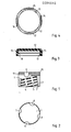
- Figur 1 ein Ausführungsbeispiel des Auflagekörpers der erfindungsgemäßen Stumpfkappe in axialer Schnittdarstellung,
- Figur 2 der Auflagekörper gemäß Figur 1 in der Draufsicht,
- Figur 3 eine Abdeckkappe für den Auflagekörper in radialer Schnittdarstellung und
- Figur 3 die Abdeckkappe gemäß Figur 2 in axial geschnittener Darstellung.
- Bei dem in Figur 1 dargestellten Auflagekörper 1, der eine im wesentlichen zylindrische Außenwandung 2 aufweist, ist im Inneren eine konische koaxiale Ausnehmung 3 vorgesehen, die mit einem Innengewinde versehen ist. Die Öffnung der Ausnehmung befindet sich auf der der geschlossenen Deckfläche gegenüberliegenden Seite. Das Innengewinde ist ein konisches, sich zum Inneren der Kappe hin verjüngendes selbstschneidendes Gewinde mit dem Profil eines Knochenschraubengewindes, wobei nach innen gerichtet Tragflanken 4 vorgesehen sind, welche von Schneidnuten 5 unterbrochen sind. Auf diese Weise kann der Auflagekörper in den meisten Fällen auf den Knochenstumpf direkt aufgeschraubt werden. Im übrigen kann eine Nachbearbeitung mit einem entsprechenden Fräser oder einer Raspel vorgenommen werden.
- Der Konus ist der Verjüngung des jeweiligen Knochentyps angepaßt, für den die Anwendung vorgesehen ist, so daß nach entsprechender Auswahl einer Kappenausführung mit geeignetem Innendurchmesser diese direkt aufschraubbar ist.
- Bei nicht dargestellten weiteren Varianten des Ausführungsbeispiels kann durch eine leicht (konkav) ballige Gestaltung der das selbstschneidende Innengewinde tragenden Innenfläche der Ausnehmung ein Aufschrauben in auch nachträglich angepaßter Richtung erfolgen. Die genaue Ausrichtung des mit einem selbstschneidenden Gewinde versehehen Auflagekörpers wird dann nach der eventuellen Nachbearbeitung des Knochenstumpfes vorgenommen. Bei konischem Innengewinde liegt hingegen die Schraubrichtung fest und wird durch die Bearbeitung des Knochenstumpfes definiert.
- In Figur 2 ist erkennbar, daß der Auflagekörper in seinem vom Knochen abgewandten Bereich Ausnehmungen 6 bis 9 in der Nähe der äußeren Kante aufweist, in die ein Schraubwerkzeug zwecks Übertragung eines Ein- bzw. Ausschraub-Drehmoments eingreifen kann.
- Unterhalb einer Fase 10 ist im zylindermantelförmigen Bereich der Außenoberfläche ein Einstich 11 vorgesehen, der einer Halt für die in den Figuren 3 und 4 dargestellt Kappe 12 bildet. Diese Kappe weist in ihrem Inneren eine Ausnehmung 13 auf, die geringfügig kleiner dimensioniert ist als die Auflage 1, so daß sie auf diese aufschnappbar ist, wenn sie aus einem elastischen Werkstoff besteht. Die Kappe 12 ist aus Polyethylen gefertigt, wobei hier sehnenförmig laufende Bohrungen 14 bis 17 im Randbereich vorgesehen sind, durch die Fäden hindurchgezogen werden könnnen, so daß die Kappe mit chirurgischem Nahtmaterial festgenäht werden kann. Die Kappe 12 weist ihrerseits an der Innenseite ebenfalls einen umlaufenden Einstich 18 auf, der bei elastischer Ausführung der Kappe die zylindrischen Innenwandungen in zwei Bereiche unterteilt, die somit jeweils ein eigenes Dichtungssystem bilden. Die Kappe 12 deckt die Ausnehmungen 6 bis 9 vollkommen ab, so daß die Kappe mit Aufsatz nach außen hin einen vollständig geschlossenen Flächenbereich darbietet.
- Die Erfindung beschränkt sich in ihrer Ausführung nicht auf das vorstehend angegebene bevorzugte Ausführungsbeispiel. Vielmehr ist eine Anzahl von Varianten denkbar, welche von der dargestellten Lösung auch bei grundsätzlich anders gearteten Ausführungen Gebrauch machen.
Claims (11)
1. Stumpfkappe, enthaltend einen Auflagekörper für den Knochenstumpf, insbesondere für den Femurstumpf, der mit der Kopffläche am unteren Abschluß des Knochenstumpfes anliegt,
dadurch gekennzeichnet,
daß der Auflagekörper (1)
im wesentlichen zylindrisch ausgebildet ist und
eine im wesentlichen koaxiale stirnseitige Ausnehmung (3) mit Innengewinde (4, 5) aufweist.
dadurch gekennzeichnet,
daß der Auflagekörper (1)
im wesentlichen zylindrisch ausgebildet ist und
eine im wesentlichen koaxiale stirnseitige Ausnehmung (3) mit Innengewinde (4, 5) aufweist.
2. Stumpfkappe nach Anspruch 1, dadurch gekennzeichnet, daß das Gewinde (4, 5) selbstschneidend ausgebildet ist.
3. Stumpfkappe nach einem der vorangehenden Ansprüche, dadurch gekennzeichnet, daß das Gewinde (4, 5) konisch verjüngend ausgebildet ist.
4. Stumpfkappe nach einem der vorangehenden Ansprüche, dadurch gekennzeichnet, daß das Gewinde (4, 5) ein Normgewinde für Knochenschrauben bildet.
5. Stumpfkappe nach einem der vorangehenden Ansprüche, dadurch gekennzeichnet, daß mindestens eine von der dem Knochen abgewandten Seite erreichbare Ausnehmung (6 bis 9) vorgesehen sind, welche einen Drehmomentanschluß für ein Schraubwerkzeug bilden.
6. Stumpfkappe nach einem der vorangehenden Ansprüche, dadurch gekennzeichnet, daß die dem Knochen abgewandte Deckfläche eine abgeschrägte Kante (10) aufweist.
7. Stumpfkappe nach einem der vorangehenden Ansprüche, dadurch gekennzeichnet, daß in der Nähe der dem Knochen abgewandten Deckfläche ein umlaufender Einstich (11) vorgesehen ist.
8. Stumpfkappe nach einem der vorangehenden Ansprüche, dadurch gekennzeichnet, daß der Auflagekörper aus Polyethylen oder Metall besteht.
9. Stumpfkappe nach einem der vorangehenden Ansprüche, dadurch gekennzeichnet, daß der Auflagekörper eine flexible Kappe (12) aufweist, die einen den Mantel teilweise übergreifenden Rand enthält.
10. Stumpfkappe nach den Ansprüchen 7 und 9, dadurch gekennzeichnet, daß der Rand eine in den Einstich eingreifende Sicke aufweist.
11. Stumpfkappe nach einem der Ansprüche 9 oder 10, dadurch gekennzeichnet, daß die Kappe aus Polyethylen besteht.
Applications Claiming Priority (2)
| Application Number | Priority Date | Filing Date | Title |
|---|---|---|---|
| DE8703120U | 1987-02-26 | ||
| DE8703120U DE8703120U1 (de) | 1987-02-26 | 1987-02-26 | Stumpfkappe |
Publications (1)
| Publication Number | Publication Date |
|---|---|
| EP0284545A1 true EP0284545A1 (de) | 1988-09-28 |
Family
ID=6805351
Family Applications (1)
| Application Number | Title | Priority Date | Filing Date |
|---|---|---|---|
| EP88730012A Withdrawn EP0284545A1 (de) | 1987-02-26 | 1988-01-16 | Stumpfkappe |
Country Status (2)
| Country | Link |
|---|---|
| EP (1) | EP0284545A1 (de) |
| DE (1) | DE8703120U1 (de) |
Cited By (3)
| Publication number | Priority date | Publication date | Assignee | Title |
|---|---|---|---|---|
| EP0681461A4 (de) * | 1993-01-28 | 1996-09-04 | Int Polymer Eng Inc | Knochenpessar und herstellungsmethode. |
| FR2912638A1 (fr) * | 2007-02-20 | 2008-08-22 | Chabloz Pierre | Dispositif de mesure pour moignon femoral |
| CN111434321A (zh) * | 2019-01-11 | 2020-07-21 | 宝楠生技股份有限公司 | 腓骨截断处的防止融合构件 |
Citations (10)
| Publication number | Priority date | Publication date | Assignee | Title |
|---|---|---|---|---|
| FR1046920A (fr) * | 1951-11-15 | 1953-12-09 | Dispositif d'appui lors des amputations de membres | |
| US3053251A (en) * | 1959-03-30 | 1962-09-11 | Black Maurice | Joint prosthesis |
| US4005495A (en) * | 1975-08-09 | 1977-02-01 | Rosenthal Technik Ag | Ceramic cap bone prosthesis and method of implantation |
| DE2548077A1 (de) * | 1974-10-29 | 1977-05-12 | Feldmuehle Anlagen Prod | Gelenkendoprothese |
| EP0006408A1 (de) * | 1978-06-30 | 1980-01-09 | HOWMEDICA INTERNATIONAL, INC. Zweigniederlassung Kiel | In eine Markhöhle einsetzbares Hilfselement zur Sicherung des Sitzes eines Implantates |
| EP0017930A1 (de) * | 1979-04-11 | 1980-10-29 | Feldmühle Aktiengesellschaft | Hüftkopfkappe für Endoprothese |
| DE3125268A1 (de) * | 1981-06-24 | 1983-01-13 | C. Nicolai GmbH & Co KG, 3000 Hannover | Implantat |
| US4547912A (en) * | 1983-09-01 | 1985-10-22 | Sherva Parker Carole J | Amputation apparatus |
| DE3439993A1 (de) * | 1984-11-02 | 1986-05-28 | Friedrichsfeld GmbH Keramik- und Kunststoffwerke, 6800 Mannheim | Implantat zur versorgung von amputationsstuempfen |
| DE8631192U1 (de) * | 1986-11-21 | 1987-03-19 | Mecron Medizinische Produkte Gmbh, 1000 Berlin | Stumpfkappe |
Family Cites Families (1)
| Publication number | Priority date | Publication date | Assignee | Title |
|---|---|---|---|---|
| DE2318459A1 (de) * | 1973-04-12 | 1974-10-31 | Feldmuehle Anlagen Prod | Kuenstlicher gelenkersatz aus gesinterter oxidkeramik |
-
1987
- 1987-02-26 DE DE8703120U patent/DE8703120U1/de not_active Expired
-
1988
- 1988-01-16 EP EP88730012A patent/EP0284545A1/de not_active Withdrawn
Patent Citations (10)
| Publication number | Priority date | Publication date | Assignee | Title |
|---|---|---|---|---|
| FR1046920A (fr) * | 1951-11-15 | 1953-12-09 | Dispositif d'appui lors des amputations de membres | |
| US3053251A (en) * | 1959-03-30 | 1962-09-11 | Black Maurice | Joint prosthesis |
| DE2548077A1 (de) * | 1974-10-29 | 1977-05-12 | Feldmuehle Anlagen Prod | Gelenkendoprothese |
| US4005495A (en) * | 1975-08-09 | 1977-02-01 | Rosenthal Technik Ag | Ceramic cap bone prosthesis and method of implantation |
| EP0006408A1 (de) * | 1978-06-30 | 1980-01-09 | HOWMEDICA INTERNATIONAL, INC. Zweigniederlassung Kiel | In eine Markhöhle einsetzbares Hilfselement zur Sicherung des Sitzes eines Implantates |
| EP0017930A1 (de) * | 1979-04-11 | 1980-10-29 | Feldmühle Aktiengesellschaft | Hüftkopfkappe für Endoprothese |
| DE3125268A1 (de) * | 1981-06-24 | 1983-01-13 | C. Nicolai GmbH & Co KG, 3000 Hannover | Implantat |
| US4547912A (en) * | 1983-09-01 | 1985-10-22 | Sherva Parker Carole J | Amputation apparatus |
| DE3439993A1 (de) * | 1984-11-02 | 1986-05-28 | Friedrichsfeld GmbH Keramik- und Kunststoffwerke, 6800 Mannheim | Implantat zur versorgung von amputationsstuempfen |
| DE8631192U1 (de) * | 1986-11-21 | 1987-03-19 | Mecron Medizinische Produkte Gmbh, 1000 Berlin | Stumpfkappe |
Cited By (3)
| Publication number | Priority date | Publication date | Assignee | Title |
|---|---|---|---|---|
| EP0681461A4 (de) * | 1993-01-28 | 1996-09-04 | Int Polymer Eng Inc | Knochenpessar und herstellungsmethode. |
| FR2912638A1 (fr) * | 2007-02-20 | 2008-08-22 | Chabloz Pierre | Dispositif de mesure pour moignon femoral |
| CN111434321A (zh) * | 2019-01-11 | 2020-07-21 | 宝楠生技股份有限公司 | 腓骨截断处的防止融合构件 |
Also Published As
| Publication number | Publication date |
|---|---|
| DE8703120U1 (de) | 1987-07-02 |
Similar Documents
| Publication | Publication Date | Title |
|---|---|---|
| DE69319204T2 (de) | Verankerungselement zum Halten von Gelenksprothesen für ein wiederhergestelltes Gelenk | |
| EP0329019B1 (de) | Gelenkpfannenteil für eine Gelenkprothese | |
| EP0482320B1 (de) | Schalenelement zur Aufnahme einer Gelenkendoprothese | |
| EP0845251B1 (de) | Bausatz für eine modulare Femurkapfprothese, insbesondere eine Reoperationsprothese, und Femurkopfprothese aus einem derartigen Bausatz | |
| DE3876804T2 (de) | Gelenkprothese. | |
| EP0791342B1 (de) | Schenkelhalsendoprothese für ein künstliches Hüftgelenk | |
| DE3334058C2 (de) | Oberschenkelteil für eine Hüftgelenkendoprothese | |
| DE69001147T2 (de) | Oberschenkelkopfanpasser zur montage waehrend der operation. | |
| DE4323956C1 (de) | Wirbelkörperfusionsdübel | |
| EP0165947B1 (de) | Künstliche gelenkpfanne | |
| DE2323456A1 (de) | Kuenstliches hueftgelenk | |
| EP0393425A1 (de) | Einzementierbares Oberschenkelteil einer Hüftgelenk-Endoprothese | |
| DE2359627A1 (de) | Ellbogengelenk-endoprothese | |
| DE69009418T2 (de) | Prothetische Vorrichtung mit Modulschaft. | |
| DE2834298A1 (de) | Endoprothese fuer ein hueftgelenk, insbesondere das hueftgelenk eines menschen | |
| DE69514621T2 (de) | Femurschaft für Hüftprothese | |
| DE3336004C2 (de) | Adapter für eine Knochen-Endoprothese | |
| EP0198163B1 (de) | Verbindung zweier Implantat-Teile | |
| DE3426947C2 (de) | Oberschenkelteil einer Hüftgelenk-Endoprothese | |
| DE2621666A1 (de) | Endoprothese fuer hueft-, knie- oder winkelgelenke | |
| EP0827386B1 (de) | Endoprothese für ein metatarsophalangealgelenk | |
| DE69401301T2 (de) | Femurteil einer Hüftgelenkprothese | |
| EP0677280A1 (de) | Hüftpfannen-Prothese | |
| DE4408527B4 (de) | Einschraubbare Hüftgelenkpfanne mit gekrümmter äußerer Kontur | |
| EP0284545A1 (de) | Stumpfkappe |
Legal Events
| Date | Code | Title | Description |
|---|---|---|---|
| PUAI | Public reference made under article 153(3) epc to a published international application that has entered the european phase |
Free format text: ORIGINAL CODE: 0009012 |
|
| AK | Designated contracting states |
Kind code of ref document: A1 Designated state(s): CH DE ES FR GB IT LI |
|
| 17P | Request for examination filed |
Effective date: 19890130 |
|
| STAA | Information on the status of an ep patent application or granted ep patent |
Free format text: STATUS: THE APPLICATION IS DEEMED TO BE WITHDRAWN |
|
| 18D | Application deemed to be withdrawn |
Effective date: 19900801 |