EP0284565B1 - Elektromagnetische Stranggiesskokille - Google Patents
Elektromagnetische Stranggiesskokille Download PDFInfo
- Publication number
- EP0284565B1 EP0284565B1 EP88810179A EP88810179A EP0284565B1 EP 0284565 B1 EP0284565 B1 EP 0284565B1 EP 88810179 A EP88810179 A EP 88810179A EP 88810179 A EP88810179 A EP 88810179A EP 0284565 B1 EP0284565 B1 EP 0284565B1
- Authority
- EP
- European Patent Office
- Prior art keywords
- inductor
- mold
- mould
- sides
- narrow sides
- Prior art date
- Legal status (The legal status is an assumption and is not a legal conclusion. Google has not performed a legal analysis and makes no representation as to the accuracy of the status listed.)
- Expired - Lifetime
Links
Images
Classifications
-
- B—PERFORMING OPERATIONS; TRANSPORTING
- B22—CASTING; POWDER METALLURGY
- B22D—CASTING OF METALS; CASTING OF OTHER SUBSTANCES BY THE SAME PROCESSES OR DEVICES
- B22D11/00—Continuous casting of metals, i.e. casting in indefinite lengths
- B22D11/01—Continuous casting of metals, i.e. casting in indefinite lengths without moulds, e.g. on molten surfaces
- B22D11/015—Continuous casting of metals, i.e. casting in indefinite lengths without moulds, e.g. on molten surfaces using magnetic field for conformation, i.e. the metal is not in contact with a mould
Definitions
- the invention relates to an electromagnetic continuous casting mold for the vertical casting of rolled ingots with an essentially rectangular cross section with an inductor arranged on the four sides of the mold and an electromagnetic screen partially covering them.
- a mold is known from EP A 0 109 357.
- rolling ingot includes casting strands with essentially rectangular, i.e. Cross-sectional dimensions having broad or rolled sides and narrow sides understood.
- heat is removed from the strand emerging from the mold by applying coolant to the surface of the strand directly below the mold.
- the coolant initially only touches the start-up floor.
- the indirect heat removal that occurs leads to a mild solidification of the liquid metal and to an even formation of the strand base.
- the coolant hits the surface of the strand, which is associated with a sudden increase in heat dissipation from the strand.
- the thermal stresses resulting from this temperature shock are greater than the tensile strength of the strand and lead to permanent deformation in the form of a convex curvature of the strand foot.
- the cooling intensity can be reduced, for example, at least during the start-up process.
- a coolant with gas dissolved in it is used, which forms an insulating film which reduces the heat flow when the coolant hits the surface of the strand.
- a significant advantage of electromagnetic over conventional continuous casting molds lies in the more uniform formation of the strand surface, which is free from cold running, exudation, surface segregation and other near-surface defects, so that in most cases there is no need to mill the strand surface.
- the electromagnetic force field generated by the inductor stimulates melt circulation in the liquid head of the strand.
- This electromagnetic turbulence can, among other things, detach the oxide skin and consequently impair the solidification conditions and the melt quality in the area of the solidifying strand surface. This manifests itself, for example, in an accumulation of oxide inclusions, in longitudinal folds and in those surface defects which only appear in the form of surface slate, looper lines and the like in the processed material.
- alloys with a strong tendency to oxidize such as e.g. B.
- the inventor has set itself the goal of further developing an electromagnetic continuous casting mold of the type mentioned at the outset in such a way that the strands can be prevented from escaping during casting, while accepting a minimal melt circulation in the liquid head of the casting strand.
- the screen is arranged or designed on the narrow sides of the mold in such a way that the electromagnetic force directed at the liquid head of the strand is greater on the narrow sides of the mold than on the broad sides thereof.
- This measure increases the electromagnetic force directed towards the middle of the strand on the narrow sides of the mold, so that a certain strand root warping can be accepted without the risk of the strand running out on its narrow sides.
- the casting process is therefore safer during the start-up process.
- the melt circulation in the liquid head of the casting strand is only slightly increased.
- the design of the mold according to the invention enables casting of large-sized rolled bars made of aluminum alloys with magnesium contents of 4% and more.
- the vertical distance between the lower edge of the inductor and the lower edge of the screen is greater on the narrow sides of the mold than on the broad sides thereof.
- the lower edges of the screen lie on the broad and narrow sides of the mold at the same height, the inductor being arranged higher on the broad sides of the mold than on its narrow sides.
- the mere shift in the position of the inductor offers the part before that the line of incidence of the coolant usually determined by the inner surface of the electromagnetic screen on the strand circumference remains unchanged.
- the inductor is arranged on the broad and narrow sides of the mold at the same height, the lower edges of the screen being higher on the narrow sides of the mold than on the broad sides thereof.
- the difference between the vertical distance between the lower edge of the screen and the lower edge of the inductor on the broad sides compared to the vertical distance between the lower edge of the screen and the lower edge of the inductor on the narrow sides of the mold is preferably a maximum 70%, preferably 10 - 30%, of the vertical dimension of the inductor.
- the screen has a different cross-section on the narrow sides of the mold or a different electrical conductivity than on the broad sides thereof.
- inductor and electromagnetic shield naturally does not only relate to molds with a fixed casting cross-section, but is also particularly suitable for molds with a variable casting cross-section, i.e. for example for a mold with stationary side walls and sliding end walls, as is known for example from EP-A-0 109 357.
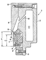
- a mold 1 has a coolant box 2, to which a support body 4 made of electrically insulating material is fastened by means of screws 3.
- This support body 4 is supported by a loop-shaped inductor 6, which is held by screws 5 and has a tubular cooling channel 7 on the back for receiving a coolant.
- a downwardly tapering electromagnetic screen 9 made of an electrically conductive, non-ferromagnetic material is fastened by means of screws 8. Screen 9 and inductor 6 create a gap 10, from which coolant is passed from a coolant chamber 11 via a channel 12 to the surface of a casting strand (not shown in the figure).
Landscapes
- Engineering & Computer Science (AREA)
- Mechanical Engineering (AREA)
- Continuous Casting (AREA)
- Braiding, Manufacturing Of Bobbin-Net Or Lace, And Manufacturing Of Nets By Knotting (AREA)
- Rehabilitation Tools (AREA)
- Reciprocating, Oscillating Or Vibrating Motors (AREA)
- Casting Or Compression Moulding Of Plastics Or The Like (AREA)
- Moulds For Moulding Plastics Or The Like (AREA)
- Medicinal Preparation (AREA)
- Confectionery (AREA)
Priority Applications (1)
| Application Number | Priority Date | Filing Date | Title |
|---|---|---|---|
| AT88810179T ATE56897T1 (de) | 1987-03-23 | 1988-03-21 | Elektromagnetische stranggiesskokille. |
Applications Claiming Priority (2)
| Application Number | Priority Date | Filing Date | Title |
|---|---|---|---|
| CH1095/87 | 1987-03-23 | ||
| CH109587 | 1987-03-23 |
Publications (2)
| Publication Number | Publication Date |
|---|---|
| EP0284565A1 EP0284565A1 (de) | 1988-09-28 |
| EP0284565B1 true EP0284565B1 (de) | 1990-09-26 |
Family
ID=4202353
Family Applications (1)
| Application Number | Title | Priority Date | Filing Date |
|---|---|---|---|
| EP88810179A Expired - Lifetime EP0284565B1 (de) | 1987-03-23 | 1988-03-21 | Elektromagnetische Stranggiesskokille |
Country Status (10)
| Country | Link |
|---|---|
| US (1) | US4796689A (no) |
| EP (1) | EP0284565B1 (no) |
| JP (1) | JPS63252644A (no) |
| AT (1) | ATE56897T1 (no) |
| AU (1) | AU607748B2 (no) |
| CA (1) | CA1315521C (no) |
| DE (1) | DE3860676D1 (no) |
| ES (1) | ES2018356B3 (no) |
| NO (1) | NO168460C (no) |
| ZA (1) | ZA881861B (no) |
Families Citing this family (1)
| Publication number | Priority date | Publication date | Assignee | Title |
|---|---|---|---|---|
| AU3041192A (en) * | 1992-01-30 | 1993-08-05 | Alusuisse-Lonza Services Ltd | Electromagnetic continuous chill casting mould |
Family Cites Families (5)
| Publication number | Priority date | Publication date | Assignee | Title |
|---|---|---|---|---|
| CH625441A5 (no) * | 1977-12-05 | 1981-09-30 | Alusuisse | |
| DE2914246C2 (de) * | 1979-03-07 | 1981-11-12 | Schweizerische Aluminium AG, 3965 Chippis | Elektromagnetische Stranggießkokille |
| US4321959A (en) * | 1979-07-11 | 1982-03-30 | Olin Corporation | Electromagnetic casting shape control by differential screening and inductor contouring |
| US4512386A (en) * | 1982-11-12 | 1985-04-23 | Swiss Aluminium Ltd. | Adjustable mold for electromagnetic casting |
| US4544016A (en) * | 1983-04-21 | 1985-10-01 | Yetselev Zinovy N | Continuous casting process and apparatus |
-
1988
- 1988-03-14 US US07/167,536 patent/US4796689A/en not_active Expired - Fee Related
- 1988-03-16 ZA ZA881861A patent/ZA881861B/xx unknown
- 1988-03-21 CA CA000561982A patent/CA1315521C/en not_active Expired - Fee Related
- 1988-03-21 AT AT88810179T patent/ATE56897T1/de not_active IP Right Cessation
- 1988-03-21 DE DE8888810179T patent/DE3860676D1/de not_active Expired - Lifetime
- 1988-03-21 NO NO881235A patent/NO168460C/no unknown
- 1988-03-21 ES ES88810179T patent/ES2018356B3/es not_active Expired - Lifetime
- 1988-03-21 EP EP88810179A patent/EP0284565B1/de not_active Expired - Lifetime
- 1988-03-23 AU AU13513/88A patent/AU607748B2/en not_active Ceased
- 1988-03-23 JP JP63069209A patent/JPS63252644A/ja active Pending
Also Published As
| Publication number | Publication date |
|---|---|
| ZA881861B (en) | 1988-09-05 |
| DE3860676D1 (de) | 1990-10-31 |
| ES2018356B3 (es) | 1991-04-01 |
| JPS63252644A (ja) | 1988-10-19 |
| ATE56897T1 (de) | 1990-10-15 |
| AU607748B2 (en) | 1991-03-14 |
| EP0284565A1 (de) | 1988-09-28 |
| CA1315521C (en) | 1993-04-06 |
| NO881235L (no) | 1988-09-26 |
| US4796689A (en) | 1989-01-10 |
| AU1351388A (en) | 1988-09-22 |
| NO168460B (no) | 1991-11-18 |
| NO881235D0 (no) | 1988-03-21 |
| NO168460C (no) | 1992-02-26 |
Similar Documents
| Publication | Publication Date | Title |
|---|---|---|
| DE4131829C2 (de) | Flüssigkeitsgekühlte Kokille für das Stranggießen von Strängen aus Stahl im Brammenformat | |
| DE3787096T2 (de) | Schmelz- und raffinierungsverfahren von metallen sowie vorrichtung zur kühlung der verwendeten elektroden. | |
| DE3879782T2 (de) | Verfahren zur herstellung eines mit kupfer ummantelten fahrdrahtes aus stahl. | |
| DE69615176T2 (de) | Giessen von stahlbändern | |
| DE2848808C2 (de) | Elektromagnetische Stranggießkokille | |
| DE3621073A1 (de) | Kokille | |
| EP0062606B1 (de) | Vorrichtung zum Kühlen eines Giessstranges während des Stranggiessens | |
| EP0109357B1 (de) | Elektromagnetische Stranggiesskokille | |
| EP0035958A2 (de) | Stranggiesskokille | |
| DE10051959A1 (de) | Verfahren und Vorrichtung zum Stranggießen und anschließendem Verformen eines Gießstranges aus Stahl, insbesondere eines Gießstranges mit Blockformat oder Vorprofil-Format | |
| EP0284565B1 (de) | Elektromagnetische Stranggiesskokille | |
| DE1508893B1 (de) | Schmelzverfahren zur Herstellung von Gussbloecken mittels Abschmelzelektroden | |
| DE69911454T2 (de) | Anordnung einer vorrichtung zum kühlen von knüppeln | |
| DE2548939C2 (de) | Verfahren und Vorrichtung zum Stranggießen von Bändern | |
| DE2426979A1 (de) | Stranggussverfahren zum giessen von bloecken oder baendern aus metall | |
| DE846900C (de) | Giessform fuer das stetige Giessen von Metallen | |
| DE69912105T2 (de) | Vorrichtung zum giesen von metall | |
| DE69702611T2 (de) | Vertikal-stranggiesskokille mit aufsatz | |
| EP0485331B1 (de) | Verfahren und Vorrichtung zum elektromagnetischen Giessen von Walzbarren mit faltenfreier Oberfläche aus einer Aluminiumlegierung | |
| DE2111849A1 (de) | Giessverfahren fuer Metalle | |
| CH363129A (de) | Verfahren zum kontinuierlichen Giessen von Metallsträngen und Kokille zum Durchführen des Verfahrens | |
| EP0229589B1 (de) | Vorrichtung und Verfahren zum Stranggiessen von Metallen | |
| DE1939653A1 (de) | Wassergekuehlte Stranggusskokille | |
| DE69703793T2 (de) | Stranggussverfahren von metallen und kokille zur durchführung dieses verfahrens | |
| DE3303484C2 (de) | Vertikal-Stranggießkokille |
Legal Events
| Date | Code | Title | Description |
|---|---|---|---|
| PUAI | Public reference made under article 153(3) epc to a published international application that has entered the european phase |
Free format text: ORIGINAL CODE: 0009012 |
|
| AK | Designated contracting states |
Kind code of ref document: A1 Designated state(s): AT BE CH DE ES FR GB IT LI LU NL SE |
|
| 17P | Request for examination filed |
Effective date: 19890227 |
|
| 17Q | First examination report despatched |
Effective date: 19890712 |
|
| RAP1 | Party data changed (applicant data changed or rights of an application transferred) |
Owner name: ALUSUISSE-LONZA SERVICES AG |
|
| ITF | It: translation for a ep patent filed | ||
| GRAA | (expected) grant |
Free format text: ORIGINAL CODE: 0009210 |
|
| AK | Designated contracting states |
Kind code of ref document: B1 Designated state(s): AT BE CH DE ES FR GB IT LI LU NL SE |
|
| REF | Corresponds to: |
Ref document number: 56897 Country of ref document: AT Date of ref document: 19901015 Kind code of ref document: T |
|
| GBT | Gb: translation of ep patent filed (gb section 77(6)(a)/1977) | ||
| REF | Corresponds to: |
Ref document number: 3860676 Country of ref document: DE Date of ref document: 19901031 |
|
| ET | Fr: translation filed | ||
| PLBE | No opposition filed within time limit |
Free format text: ORIGINAL CODE: 0009261 |
|
| STAA | Information on the status of an ep patent application or granted ep patent |
Free format text: STATUS: NO OPPOSITION FILED WITHIN TIME LIMIT |
|
| 26N | No opposition filed | ||
| ITTA | It: last paid annual fee | ||
| PGFP | Annual fee paid to national office [announced via postgrant information from national office to epo] |
Ref country code: FR Payment date: 19930218 Year of fee payment: 6 Ref country code: CH Payment date: 19930218 Year of fee payment: 6 |
|
| PGFP | Annual fee paid to national office [announced via postgrant information from national office to epo] |
Ref country code: LU Payment date: 19930224 Year of fee payment: 6 |
|
| PGFP | Annual fee paid to national office [announced via postgrant information from national office to epo] |
Ref country code: SE Payment date: 19930225 Year of fee payment: 6 Ref country code: AT Payment date: 19930225 Year of fee payment: 6 |
|
| PGFP | Annual fee paid to national office [announced via postgrant information from national office to epo] |
Ref country code: DE Payment date: 19930303 Year of fee payment: 6 |
|
| PGFP | Annual fee paid to national office [announced via postgrant information from national office to epo] |
Ref country code: ES Payment date: 19930305 Year of fee payment: 6 |
|
| PGFP | Annual fee paid to national office [announced via postgrant information from national office to epo] |
Ref country code: GB Payment date: 19930310 Year of fee payment: 6 Ref country code: BE Payment date: 19930310 Year of fee payment: 6 |
|
| PGFP | Annual fee paid to national office [announced via postgrant information from national office to epo] |
Ref country code: NL Payment date: 19930331 Year of fee payment: 6 |
|
| EPTA | Lu: last paid annual fee | ||
| PG25 | Lapsed in a contracting state [announced via postgrant information from national office to epo] |
Ref country code: LU Free format text: LAPSE BECAUSE OF NON-PAYMENT OF DUE FEES Effective date: 19940321 Ref country code: GB Effective date: 19940321 Ref country code: AT Effective date: 19940321 |
|
| PG25 | Lapsed in a contracting state [announced via postgrant information from national office to epo] |
Ref country code: SE Free format text: LAPSE BECAUSE OF NON-PAYMENT OF DUE FEES Effective date: 19940322 Ref country code: ES Free format text: LAPSE BECAUSE OF NON-PAYMENT OF DUE FEES Effective date: 19940322 |
|
| PG25 | Lapsed in a contracting state [announced via postgrant information from national office to epo] |
Ref country code: LI Effective date: 19940331 Ref country code: CH Effective date: 19940331 Ref country code: BE Effective date: 19940331 |
|
| BERE | Be: lapsed |
Owner name: ALUSUISSE-LONZA SERVICES A.G. Effective date: 19940331 |
|
| PG25 | Lapsed in a contracting state [announced via postgrant information from national office to epo] |
Ref country code: NL Effective date: 19941001 |
|
| GBPC | Gb: european patent ceased through non-payment of renewal fee |
Effective date: 19940321 |
|
| NLV4 | Nl: lapsed or anulled due to non-payment of the annual fee | ||
| PG25 | Lapsed in a contracting state [announced via postgrant information from national office to epo] |
Ref country code: FR Effective date: 19941130 |
|
| REG | Reference to a national code |
Ref country code: CH Ref legal event code: PL |
|
| PG25 | Lapsed in a contracting state [announced via postgrant information from national office to epo] |
Ref country code: DE Effective date: 19941201 |
|
| REG | Reference to a national code |
Ref country code: FR Ref legal event code: ST |
|
| EUG | Se: european patent has lapsed |
Ref document number: 88810179.7 Effective date: 19941010 |
|
| REG | Reference to a national code |
Ref country code: ES Ref legal event code: FD2A Effective date: 19990405 |
|
| PG25 | Lapsed in a contracting state [announced via postgrant information from national office to epo] |
Ref country code: IT Free format text: LAPSE BECAUSE OF NON-PAYMENT OF DUE FEES;WARNING: LAPSES OF ITALIAN PATENTS WITH EFFECTIVE DATE BEFORE 2007 MAY HAVE OCCURRED AT ANY TIME BEFORE 2007. THE CORRECT EFFECTIVE DATE MAY BE DIFFERENT FROM THE ONE RECORDED. Effective date: 20050321 |