EP0284589B1 - Elektrisches Sicherheitsschloss - Google Patents
Elektrisches Sicherheitsschloss Download PDFInfo
- Publication number
- EP0284589B1 EP0284589B1 EP88870038A EP88870038A EP0284589B1 EP 0284589 B1 EP0284589 B1 EP 0284589B1 EP 88870038 A EP88870038 A EP 88870038A EP 88870038 A EP88870038 A EP 88870038A EP 0284589 B1 EP0284589 B1 EP 0284589B1
- Authority
- EP
- European Patent Office
- Prior art keywords
- latch
- lock
- lever
- characteristic
- electrical safety
- Prior art date
- Legal status (The legal status is an assumption and is not a legal conclusion. Google has not performed a legal analysis and makes no representation as to the accuracy of the status listed.)
- Expired - Lifetime
Links
- 239000011796 hollow space material Substances 0.000 claims description 2
- 238000010586 diagram Methods 0.000 description 5
- 230000011664 signaling Effects 0.000 description 3
- 229910000831 Steel Inorganic materials 0.000 description 2
- 239000010959 steel Substances 0.000 description 2
- 241000475699 Euphaedusa digonoptyx comes Species 0.000 description 1
- 238000013459 approach Methods 0.000 description 1
- 239000003990 capacitor Substances 0.000 description 1
- 238000000034 method Methods 0.000 description 1
- 230000000284 resting effect Effects 0.000 description 1
Images


Classifications
-
- E—FIXED CONSTRUCTIONS
- E05—LOCKS; KEYS; WINDOW OR DOOR FITTINGS; SAFES
- E05B—LOCKS; ACCESSORIES THEREFOR; HANDCUFFS
- E05B47/00—Operating or controlling locks or other fastening devices by electric or magnetic means
- E05B47/02—Movement of the bolt by electromagnetic means; Adaptation of locks, latches, or parts thereof, for movement of the bolt by electromagnetic means
- E05B47/023—Movement of the bolt by electromagnetic means; Adaptation of locks, latches, or parts thereof, for movement of the bolt by electromagnetic means the bolt moving pivotally or rotatively
-
- E—FIXED CONSTRUCTIONS
- E05—LOCKS; KEYS; WINDOW OR DOOR FITTINGS; SAFES
- E05B—LOCKS; ACCESSORIES THEREFOR; HANDCUFFS
- E05B47/00—Operating or controlling locks or other fastening devices by electric or magnetic means
- E05B47/0001—Operating or controlling locks or other fastening devices by electric or magnetic means with electric actuators; Constructional features thereof
- E05B47/0002—Operating or controlling locks or other fastening devices by electric or magnetic means with electric actuators; Constructional features thereof with electromagnets
-
- E—FIXED CONSTRUCTIONS
- E05—LOCKS; KEYS; WINDOW OR DOOR FITTINGS; SAFES
- E05B—LOCKS; ACCESSORIES THEREFOR; HANDCUFFS
- E05B47/00—Operating or controlling locks or other fastening devices by electric or magnetic means
- E05B2047/0084—Key or electric means; Emergency release
- E05B2047/0086—Emergency release, e.g. key or electromagnet
-
- E—FIXED CONSTRUCTIONS
- E05—LOCKS; KEYS; WINDOW OR DOOR FITTINGS; SAFES
- E05B—LOCKS; ACCESSORIES THEREFOR; HANDCUFFS
- E05B47/00—Operating or controlling locks or other fastening devices by electric or magnetic means
- E05B47/0001—Operating or controlling locks or other fastening devices by electric or magnetic means with electric actuators; Constructional features thereof
- E05B47/0002—Operating or controlling locks or other fastening devices by electric or magnetic means with electric actuators; Constructional features thereof with electromagnets
- E05B47/0003—Operating or controlling locks or other fastening devices by electric or magnetic means with electric actuators; Constructional features thereof with electromagnets having a movable core
- E05B47/0004—Operating or controlling locks or other fastening devices by electric or magnetic means with electric actuators; Constructional features thereof with electromagnets having a movable core said core being linearly movable
Definitions
- the present invention relates to an electrical safety lock of the type described in the preamble of claim 1.
- the invention concerns a safety lock of this type which is controlled electro-mechanically.
- electro-mechanically controlled safety locks are already known; in all them, the electromagnet is kept energized in order to hold the latch in the lock, so that whenever power to the electromagnet is interrupted, either deliberately or inadvertently, the latch emerges from the lock and so automatically locks the door.
- the aim of the present invention is to circumvent this disadvantage of known types of safety lock, by providing an electro-mechanical safety lock which can be brought, by mechanical means using a key, into either of two positions and held there automatically, ie. with the latch either in or out of the lock. In either case the key may be withdrawn from the lock.
- the invention relates to a safety lock, comprising a latch; a spring which acts on this latch, so continually trying to force it out of the lock case; a lever and shaft mechanism between this latch and the armature of a solenoid, such that the latch is drawn back into the lock case when the solenoid is energized, or, when the solenoid is deenergized, the latch is forced out of the lock case by the action of the abovementioned spring; and, at the other end of the solenoid armature, a mechanism which enables the latch to be moved back into or out of the lock case by means of a cylinder lock and key when the solenoid is not energized, wherein the end of the armature of the solenoid opposite to the latch has an extension which operates in conjunction with a slider, characterized in that said slider operates in conjunction with a locking bar which can be brought by the action of the bit of a cylinder lock in positions to engage with or disengage from a locking element.
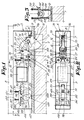
- Figs. 1 to 6 show schematically a door panel 1 with a mortice 2, and opposite a fixed section of wall 3 in which is fitted a lock 4 according to the invention, preferably mounted in a burglar-proof lock case 5.
- the lock 4 consists essentially of a latch 6 which is freely hinged on an axis 7.
- a torsion spring 8 Around the axis 7 is a torsion spring 8 with two arms, one of which acts against the outer wall of the base plate 9 and the other against a stop 10 on the latch 6.
- the latch 6 has a recess 11 into which fits the end of a a curved lever 12.
- This lever 12 has a pin 13 which projects on either side of it.
- the projecting ends of the pin 13 slide in slots 14 in the cheeks 15-16 on either side of the recess 11.
- the other end of the lever 12 hinges freely on an axis 17 mounted on the base plate 9.
- a second lever 18 is also freely hinged on the axis 17.
- This second lever 18 consists of two parts 19 and 20 situated on either side of the first lever 12. These two parts 19 and 20 are attached to each other at the base by a bridge 21 underneath which there is a spring 22 which continually tries to make the lever 18 hinge towards the latch 6.
- each of the parts 19 and 20 of the lever 18 there is a slot 23 in which slide the ends of a pin 24 mounted in the lever 12 and to which are attached the end of a forked shaft 25.
- the other end of this shaft 25 is attached to the end of the armature 27 of a solenoid 28 via an axis 26 on which it hinges freely.
- the other end of the armature 27 is extended by a shaft 29 which emerges from the solenoid 28 and which terminates in a pusher block 30.
- the pusher block 30 can move within a hollow space 31 in a slider 32 which slides in guide blocks 33-34 mounted on the base plate 9.
- the slide 32 has a groove 35 with sloping edges 36.
- the locking bar 39 has on the front a notch 44 which forms a sort of hook, and also a projection 45 opposite the groove 35.
- the slider 32 Underneath the slider 32 is a key-operated cylinder lock 47 with a projecting bit 48.
- a bolt 49 with a suitably rounded end and which operates on the door 1 or similar.
- a bridge 50 which passes over the extension of the solenoid armature 27 and whose two feet 51-52 are wide at the base.
- the bolt 49 is guided by the bridge 50 sliding on two pins 53 and 54 attached to the base plate 9.
- springs, respectively 55 and 56 On each of the pins 53 and 54 there are springs, respectively 55 and 56, which push the bridge 50 toward the base plate 9, such that these springs try to force the bolt 49 out of the lock.
- the latch is held in the mortice 2 essentially by the action of the torsion spring 8. At this moment the solenoid is not energized.
- the solenoid 28 is energized so that, as shown in fig. 4, the latch 6 is withdrawn from the mortice 2 against the resistance of the spring 8.
- the solenoid armature 27 moves towards the left in the figures, it first swings the lever 18 counterclockwise and simultaneously through the action of lever 12 swings the latch clockwise, which is possible because the lever 18 will first have moved out of the way.
- Fig. 6 shows the final position in which the lock according to the invention is held open.
- the cylinder 47 may be turned with a key so that the bit 48 also turns and engages in the groove 35 and operates on the projection 45 of the locking bar 39, thus forcing the locking bar upwards against the resistance of the springs 41 and 42, so that when the locking bar subsequently comes back down again when the slider 32 is slid, the notch 44 hooks over the pin 46, with the result that the lock is brought into the position shown in fig. 6 and held there until the cylinder 47 is turned in the other direction, thus returning the lock to the position shown in fig. 5.
- Figs. 7 to 16 show a variant which is essentially similar to the variant shown in figs. 1 to 6, with the same parts indicated by the same numbers.
- the lock is fitted with a proximity switch 59 which terminates on the outside surface of the base plate 9 and which is influenced by the steel door or a steel part mounted on the door, so that the lock may react when the door approaches.
- a stop 60 which can come up against the inside of the base plate 9 in order to prevent the latch coming too far out of the lock.
- This lever replaces the stop 21 in the first variant.
- Arm 62 of the lever 61 can be operated on by foot 51 of the bridge 50, while the other arm 63 is situated behind a projection 64 on the lever 18.
- a torsion spring 65 is wound around the axis 17, with one arm of the spring round the projection 64 and the other arm resting against the base plate 9. This spring has essentially the same function as the spring 22 in the first variant.
- the purpose of the lever 61 is to draw back the lever 18, i.e. to make it swivel counterclockwise whenever the bolt 49 emerges from the base plate. This is achieved by the projection 51 pressing on the arm 62 of the lever 61 under the action of springs 55 and 56, so that the other arm 63 of the lever 61 presses against the projection 64 on the lever 18.
- the projection 51 pressing on the arm 62 of the lever 61 under the action of springs 55 and 56, so that the other arm 63 of the lever 61 presses against the projection 64 on the lever 18.
- the projection 51 is moved out of the way of the arm 62, thus enabling the torsion spring 65, which presses against the projection 64, to bring the lever 18 into the safety or locked position, ie. with the notch 57 of the lever 18 above the 58 spur of the latch 6.
- the shaft 25 is joined to a projecting part of the solenoid armature 27 and has a cam 67.
- the bridge 66 operates in conjunction with the cam 67 of the shaft 25 in order to prevent sabotage.
- the lever 18 has on its other side a projection 68 that can operate in conjunction with a microswitch 69 on a mounting plate 70 attached to the base plate 9.
- microswitch The purpose of the microswitch is to indicate whether the latch 6 is in the locked position, when the lock is connected to a signalling system.
- the mechanical locking is also provided by a slider 32 with a groove 35 into which the end 45 of the locking bar 39 fits.
- the locking bar 39 is positioned transversely with respect to the length of the lock, and can be moved to one side or other of a ridge 71 on the guide blocks 33 and 34.
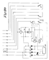
- the slider 32 Underneath the slider 32 is an integrated circuit 72 which controls the operation of the lock and which contains amongst other things a microswitch 73 operated by the pusher block 30 of the solenoid 28.
- the solenoid 28 When it is wished to draw the latch 6 back into the lock, the solenoid 28 is energized so that the pusher block 30 depresses the microswitch 73, in order to reduce the power drawn by the solenoid to a level sufficient to hold it in that position, so that it heats up less.
- the integrated circuit 72 consists essentially of: a transformer 74 to reduce the voltage to 24 volts; a rectifier bridge 75 to convert the 24 V AC to 24 V DC; a capacitor 76 to smooth the output from the rectifier bridge 75; four rectifiers 77-78-79-80 connected in bridge configuration to supply the solenoid 28; a printed circuit relay 81 to switch a signalling contact and to switch the solenoid 28; and, in combination with the microswitch 82 and printed circuit relay 81, the proximity switch 59.
- the integrated circuit 72 is connected to a control and signalling panel (not shown) on which there is a pushbutton S together with LEDs indicating the position of the lock at any given moment.
- the lock according to the invention is in the position shown in fig. 7.
- the pusher block 30 of the solenoid 28 operates the microswitch 78, so reducing the power drawn by the solenoid to a level sufficient to hold the solenoid in a drawn-in position.
- the latch 6 is thus drawn into the lock, so that the door can be opened.
- the proximity switch 59 connects the printed circuit relay 81, thus closing the relay contact.
- the proximity switch 59 reconnects the printed circuit relay 81 once more, so that the abovementioned relay contact opens once more.
Landscapes
- Physics & Mathematics (AREA)
- Electromagnetism (AREA)
- Lock And Its Accessories (AREA)
- Burglar Alarm Systems (AREA)
- Mechanical Pencils And Projecting And Retracting Systems Therefor, And Multi-System Writing Instruments (AREA)
- Developing Agents For Electrophotography (AREA)
- Supporting Of Heads In Record-Carrier Devices (AREA)
- Devices For Conveying Motion By Means Of Endless Flexible Members (AREA)
Claims (21)
- Elektrisches Sicherheitsschloß, das folgendes umfaßt: eine Klinke (6); eine Feder (8), die auf diese Klinke (6) dergestalt einwirkt, daß sie ständig versucht, letztere aus dem Schloßgehäuse (5) zu drücken; einen Hebel (12) und einen Schaft (25) zwischen der Klinke (6) und dem Anker (27) eines Solenoids (28), mit dessen Hilfe die Klinke (6) in das Schloßgehäuse (5) gezogen wird, wenn das Solenoid (28) unter Strom gesetzt wird, und mit dessen Hilfe weiterhin die Klinke (6) aus dem Schloßgehäuse (5) gedrückt wird, unter Einwirkung obengenannter Feder (8), wenn das Solenoid abgeschaltet ist, sowie einen Mechanismus (32-39-46-71-48) am anderen Ende des Ankers (27) des Solenoids (28), der es ermöglicht, die Klinke (6) in das Schloßgehäuse (5) zurück oder aus dem Schloßgehäuse (5) heraus zu bewegen mit Hilfe eines Schlüssels und eines Zylinderschlosses (47), sobald das Solenoid (28) nicht unter Strom steht, worin das der Klinke (6) gegenüberliegende Ende des Ankers (27) des Solenoids (28) eine Verlängerung (29-30) hat, die in Verbindung mit einem Schieber (32) arbeitet, was dadurch gekennzeichnet wird, daß besagter Schieber (32) gemeinsam mit einer Arretierstange (39) arbeitet, die durch Einwirken des Bartes (48) eines Zylinderschlosses (47) in Stellungen gebracht werden kann, die sie in das Verriegelungselement (46, 71) eingreifen lassen oder aus diesem lösen.
- Elektrisches Sicherheitsschloß wie in Anspruch 1, mit dem Merkmal, daß die Klinke (6) frei auf einer Achse (7) angeordnet ist, die an der Grundplatte (9) des Schloßgehäuses (5) befestigt ist, mit einer sich um die Achse windenden Torsionsfeder (8), die gegen die Außenwand der Grundplatte (9) und gegen einen Anschlag (10) auf der Klinke wirkt.
- Elektrisches Sicherheitsschloß wie in den Ansprüchen 1 oder 2, mit dem Merkmal, daß ein Hebel (12) frei schwenkbar auf der Klinke (6) angeordnet und auch am Anker (27) eines Solenoids (28) befestigt ist.
- Elektrisches Sicherheitsschloß wie in Anspruch 3, mit dem Merkmal, daß der Hebel (12) gekrümmt ist; ein Ende des Hebels ist schwenkbar an einer Achse (17) befestigt, die wiederum an dem Schloßgehäuse (5) befestigt ist; das andere Ende des Hebels ist an einer Achse (13) befestigt, die in einem Schlitz (14) in der Klinke (6) gleitet.
- Elektrisches Sicherheitsschloß wie in Anspruch 4, mit dem Merkmal, daß zwischen den obenerwähnten Befestigungspunkten (17) und (13) der Hebel (12) frei schwenkbar an einer Achse (24) angeordnet ist, über die er an einem Schaft (25) befestigt ist, dessen anderes Ende mit einem Ende des Ankers (27) des Solenoids (28) verbunden ist.
- Elektrisches Sicherheitsschloß wie in einem der obigen Ansprüche, mit dem Merkmal, daß an der Achse (17) ebenfalls ein zweiter Hebel (18) frei schwenkbar befestigt ist, auf den eine Feder (22) oder (65) einwirkt, die ständig versucht, den Hebel in Richtung auf die Klinke zu schwenken.
- Elektrisches Sicherheitsschloß wie in Anspruch 6, mit dem Merkmal, daß sich in der Nähe des Hebels (18) ein Bolzen (49) befindet, der aus dem Schloßgehäuse (5) austritt und in das Schloßgehäuse zurückgepreßt werden kann gegen den Widerstand von Federn (55-56) durch Betätigen der Tür (1), Wo dieser Bolzen (49) mindestens einen Anschlag (51-52) besitzt, der - wenn die Tür offen ist - auf einen Anschlag (21) auf dem Hebel (18) einwirkt, um letzteren gegen den Widerstand der Feder (22) zu drehen, so daß er aus dem Weg der Klinke entfernt wird (6).
- Elektrisches Sicherheitsschloß wie in Anspruch 6, mit dem Merkmal, daß sich in der Nähe des Hebels (18) ein Bolzen (49) befindet, der aus dem Schloßgehäuse (5) tritt und gegen den Widerstand von Federn (55-56) durch das Betätigen der Tür (1) in das Schloßgehäuse zurückgepreßt werden kann, wo dieser Bolzen (49) mindestens einen Anschlag (51-52) besitzt, der bei offener Tür in Verbindung mit einem Arm (62) eines L-förmigen Hebels (61) wirkt, der frei schwenkbar an obenerwähnter Achse (17) befestigt ist, und wo der andere Arm (63) dieses Hebels hinter einer Auskragung (64) auf dem Hebel (18) angeordnet ist, um letzteren gegen den Widerstand der Feder (65) zu drehen, damit er aus dem Weg der Klinke entfernt wird (6).
- Elektrisches Sicherheitsschloß wie in jedem der obigen Ansprüche, mit dem Merkmal, daß sich auf der Klinke (6) eine Auskragung befindet, die - wenn der Bolzen (49) zurück in das Schloßgehäuse (5) gedrückt wird - in Verbindung mit einer Kerbe (57) in dem Hebel (18) arbeiten kann.
- Elektrisches Sicherheitsschloß wie in jedem der obigen Ansprüche, mit dem Merkmal, daß der Schieber (32) mit einer Nut (35) versehen ist, in der der Bart (48) des Zylinderschlosses (47) eingreifen kann, um den Schieber in die eine oder andere Richtung zu bewegen und so über den Anker (27), den Schaft (25) und den Hebel (12) auf die Klinke (6) einzuwirken.
- Elektrisches Sicherheitsschloß wie in Anspruch 10, mit dem Merkmal, daß die Verlängerung (29-30) durch einen Schaft (29) gebildet wird, der durch das freie Ende des Schiebers (32) verläuft, wo letzterer einen Hohlraum (31) aufweist, in dem sich ein am freien Ende des Schaftes (29) befestigter Schiebeblock bewegen kann.
- Elektrisches Sicherheitsschloß wie in Anspruch 11, mit dem Merkmal, daß unter dem Schieber (32) und im Weg des Schiebeblocks (30) ein Mikroschalter (73) angeordnet ist, auf den der Schiebeblock (30) einwirkt, wenn das Solenoid betätigt wird, um die dem Solenoid zugeführte Leistung auf ein "Halte"-Niveau zu reduzieren.
- Elektrisches Sicherheitsschloß wie in Anspruch 11, mit dem Merkmal, daß die Länge des Raumes (31) etwas größer ist als die Breite des in ihm untergebrachten Schiebeblocks (30), zuzüglich der Entfernung, die der Solenoid-Anker (27) zurücklegen muß, um die Klinke in das Schloßgehäuse (5) zurückzubringen.
- Elektrisches Sicherheitsschloß wie in Anspruch 10, mit dem Merkmal, daß der Schieber (32) gemeinsam mit einer Arretierstange (39), die eine hakenformige Kerbe (44) hat, die über einem Stift (46) einhaken kann, arbeitet.
- Elektrisches Sicherheitsschloß wie in Anspruch 10, mit dem Merkmal, daß der Schieber (32) gemeinsam mit einer Arretierstange (39), die auf die eine oder andere Seite eines Grates (71) auf den Gleitstücken (33-34) bewegt werden kann, arbeitet.
- Elektrisches Sicherheitsschloß wie in Anspruch 14 oder 15, mit dem Merkmal, daß der Schieber (32) in Gleitstücken (33-34) schieben kann.
- Elektrisches Sicherheitsschloß wie in Anspruch 14 oder 15, mit dem Merkmal, daß die Arretierstange (39) ein Ende (45) hat, das in der Kerbe (35) im Schieber (32) paßt, und worauf der Bart (48) des Zylinders (47) einwirken kann.
- Elektrisches Sicherheitsschloß wie in Anspruch 14 oder 15, mit dem Merkmal, daß die Arretierstange (39) am Schieber (32) befestigt ist mittels Stifte (37-38) auf denen sie schieben kann,wobei Feder (40-41) über den Stiften (37-38) zwischen der Arretierstange (39) und Anschläge (42-43) auf den Enden der Stifte (37-38) montiert sind.
- Elektrisches Sicherheitsschloß wie in einem der obigen Ansprüche, mit dem Merkmal, daß sich auf dem Schaft (25), der über dem Bolzen (49) und zwischen den Federn (55) und (56) montiert ist, ein Daum (67) befindet, wobei sich rund um dem Schaften (25), oder rund um dem Ende des Ankers (27) des Solenoids an dem der Schaft (25) befestigt ist, eine Brücke (66) befindet, die am Bolzen (49) befestigt ist, so daß, falls der Solenoid nicht unter Strom steht, der Bolzen (49) nicht genügend weit aus dem Schloßgehäuse bewegen kann, damit der Hebel (18) zurückbewegt.
- Elektrisches Sicherheitsschloß wie in einem der obigen Ansprüche, mit dem Merkmal, daß der Hebel (18) eine Seitenauskragung (68) hat, die in Verbindung mit einem Mikroschalter (69) wirken kann, um auf einer Signaltafel die Stellung der Klinke (6) anzuzeigen.
- Elektrisches Sicherheitsschloß wie in einem der obigen Ansprüche, mit dem Merkmal, daß es mit einem Annäherungsschalter, der von der Grundplatte (9) herausragt, versehen ist.
Priority Applications (1)
| Application Number | Priority Date | Filing Date | Title |
|---|---|---|---|
| AT88870038T ATE82032T1 (de) | 1987-03-23 | 1988-03-10 | Elektrisches sicherheitsschloss. |
Applications Claiming Priority (2)
| Application Number | Priority Date | Filing Date | Title |
|---|---|---|---|
| BE8700292A BE1000420A7 (nl) | 1987-03-23 | 1987-03-23 | Elektrisch veiligheidsslot. |
| BE8700292 | 1987-03-23 |
Publications (3)
| Publication Number | Publication Date |
|---|---|
| EP0284589A2 EP0284589A2 (de) | 1988-09-28 |
| EP0284589A3 EP0284589A3 (en) | 1989-12-06 |
| EP0284589B1 true EP0284589B1 (de) | 1992-11-04 |
Family
ID=3882583
Family Applications (1)
| Application Number | Title | Priority Date | Filing Date |
|---|---|---|---|
| EP88870038A Expired - Lifetime EP0284589B1 (de) | 1987-03-23 | 1988-03-10 | Elektrisches Sicherheitsschloss |
Country Status (5)
| Country | Link |
|---|---|
| EP (1) | EP0284589B1 (de) |
| AT (1) | ATE82032T1 (de) |
| AU (1) | AU597808B2 (de) |
| BE (1) | BE1000420A7 (de) |
| DE (1) | DE3875642T2 (de) |
Cited By (1)
| Publication number | Priority date | Publication date | Assignee | Title |
|---|---|---|---|---|
| DE10249248A1 (de) * | 2002-10-23 | 2004-05-13 | Kurz, Oliver | Schließsystem |
Families Citing this family (9)
| Publication number | Priority date | Publication date | Assignee | Title |
|---|---|---|---|---|
| GB8829961D0 (en) * | 1988-12-22 | 1989-02-15 | Electronic Surveillance Produc | Lock mechanisms |
| SE464648B (sv) * | 1989-03-21 | 1991-05-27 | Stendals El Ab | Elektriskt slutbleck foer doerrlaas |
| DE4124944C1 (de) * | 1991-07-27 | 1992-08-13 | Dorma Gmbh + Co. Kg, 5828 Ennepetal, De | |
| AUPM409094A0 (en) * | 1994-02-25 | 1994-03-24 | Trimec Securities Pty. Limited | Improvements in electromagnetic locks |
| US7252311B2 (en) * | 2003-09-17 | 2007-08-07 | Hartwell Corporation | Motor driven latch |
| DE102007017521A1 (de) | 2007-04-13 | 2008-10-16 | Assa Abloy Sicherheitstechnik Gmbh | Hochsicherheitsschloss |
| DE102012001787A1 (de) | 2012-01-31 | 2013-08-01 | Assa Abloy Sicherheitstechnik Gmbh | Türöffner und Tür mit Türöffner |
| US12612803B2 (en) * | 2022-08-31 | 2026-04-28 | Assa Abloy Access And Egress Hardware Group, Inc. | Electronic latch retraction for mortise lock and methods of operation |
| TWI887935B (zh) * | 2023-04-17 | 2025-06-21 | 競泰股份有限公司 | 電控複合鎖 |
Family Cites Families (4)
| Publication number | Priority date | Publication date | Assignee | Title |
|---|---|---|---|---|
| FR1482332A (fr) * | 1966-06-03 | 1967-05-26 | Serrure de porte, en particulier pour corridors ou couloirs analogues | |
| AU501920B2 (en) * | 1975-11-21 | 1979-07-05 | Access Control Systems Australia Pty. Ltd | Electrically actuated doorlock |
| US4237711A (en) * | 1978-02-10 | 1980-12-09 | Brink's Locking Systems, Inc. | Lock mechanism |
| US4557121A (en) * | 1983-08-22 | 1985-12-10 | Security Engineering, Inc. | Electric fail-secure/fail-open lock mechanism |
-
1987
- 1987-03-23 BE BE8700292A patent/BE1000420A7/nl not_active IP Right Cessation
-
1988
- 1988-03-10 EP EP88870038A patent/EP0284589B1/de not_active Expired - Lifetime
- 1988-03-10 DE DE8888870038T patent/DE3875642T2/de not_active Expired - Fee Related
- 1988-03-10 AT AT88870038T patent/ATE82032T1/de not_active IP Right Cessation
- 1988-03-22 AU AU13716/88A patent/AU597808B2/en not_active Ceased
Cited By (1)
| Publication number | Priority date | Publication date | Assignee | Title |
|---|---|---|---|---|
| DE10249248A1 (de) * | 2002-10-23 | 2004-05-13 | Kurz, Oliver | Schließsystem |
Also Published As
| Publication number | Publication date |
|---|---|
| DE3875642T2 (de) | 1993-03-18 |
| AU597808B2 (en) | 1990-06-07 |
| BE1000420A7 (nl) | 1988-12-06 |
| AU1371688A (en) | 1988-09-22 |
| EP0284589A2 (de) | 1988-09-28 |
| EP0284589A3 (en) | 1989-12-06 |
| DE3875642D1 (de) | 1992-12-10 |
| ATE82032T1 (de) | 1992-11-15 |
Similar Documents
| Publication | Publication Date | Title |
|---|---|---|
| US4330958A (en) | Gate-opening and closing assembly with automatic locking means | |
| US5690373A (en) | Electromagnetic lock | |
| US3730574A (en) | Latch bolt retractor mechanism | |
| US5823582A (en) | Electromagnetically-managed latching exit bar | |
| US6386597B1 (en) | Dual latch retraction system for exit bar | |
| CA1123865A (en) | Electrically actuated overhead garage door opener assembly | |
| US6474120B1 (en) | Bolt assembly | |
| EP0284589B1 (de) | Elektrisches Sicherheitsschloss | |
| US4875722A (en) | Exit device actuator and dogger | |
| EP0259112A2 (de) | Panikbeschlag mit Sicherheitsvorrichtung | |
| NO172553B (no) | Doerlaas | |
| CA3002386C (en) | Electric door strike having a dead latch release platform actuated by a spring latch keeper and a spring latch lifter feature | |
| US4854619A (en) | Electric key | |
| GB2225375A (en) | Electromechanical door lock | |
| JPS62225667A (ja) | 電磁石的に制御された金庫用錠前 | |
| US4887442A (en) | Electronic lockset assembly and control | |
| US20040212197A1 (en) | Overhead door locking apparatus and method of operation | |
| KR20070099557A (ko) | 솔레노이드에 의해 해제되는 래치를 이용한 버티컬 도어잠금장치 | |
| WO1989002967A1 (en) | Electrically controlled locks | |
| US5718135A (en) | Locks | |
| US6539760B1 (en) | Monitoring device | |
| EP0535497B1 (de) | Verbesserter Schloss mit einer Einrichtung zwecks Öffnen im Notfall | |
| NL8403891A (nl) | Slot met uitwendige schootontgrendeling. | |
| GB2230550A (en) | Electromagnetic door lock | |
| JPH02161084A (ja) | 電気的に制御された本締り機構 |
Legal Events
| Date | Code | Title | Description |
|---|---|---|---|
| PUAI | Public reference made under article 153(3) epc to a published international application that has entered the european phase |
Free format text: ORIGINAL CODE: 0009012 |
|
| AK | Designated contracting states |
Kind code of ref document: A2 Designated state(s): AT BE CH DE ES FR GB IT LI LU NL SE |
|
| PUAL | Search report despatched |
Free format text: ORIGINAL CODE: 0009013 |
|
| AK | Designated contracting states |
Kind code of ref document: A3 Designated state(s): AT BE CH DE ES FR GB IT LI LU NL SE |
|
| 17P | Request for examination filed |
Effective date: 19900103 |
|
| RAP1 | Party data changed (applicant data changed or rights of an application transferred) |
Owner name: INSETEC NAAMLOZE VENNOOTSCHAP |
|
| 17Q | First examination report despatched |
Effective date: 19910712 |
|
| GRAA | (expected) grant |
Free format text: ORIGINAL CODE: 0009210 |
|
| AK | Designated contracting states |
Kind code of ref document: B1 Designated state(s): AT BE CH DE ES FR GB IT LI LU NL SE |
|
| PG25 | Lapsed in a contracting state [announced via postgrant information from national office to epo] |
Ref country code: IT Free format text: LAPSE BECAUSE OF FAILURE TO SUBMIT A TRANSLATION OF THE DESCRIPTION OR TO PAY THE FEE WITHIN THE PRE;WARNING: LAPSES OF ITALIAN PATENTS WITH EFFECTIVE DATE BEFORE 2007 MAY HAVE OCCURRED AT ANY TIME BEFORE 2007. THE CORRECT EFFECTIVE DATE MAY BE DIFFERENT FROM THE ONE RECORDED.SCRIBED TIME-LIMIT Effective date: 19921104 Ref country code: NL Effective date: 19921104 Ref country code: LI Effective date: 19921104 Ref country code: SE Effective date: 19921104 Ref country code: ES Free format text: THE PATENT HAS BEEN ANNULLED BY A DECISION OF A NATIONAL AUTHORITY Effective date: 19921104 Ref country code: AT Effective date: 19921104 Ref country code: CH Effective date: 19921104 |
|
| REF | Corresponds to: |
Ref document number: 82032 Country of ref document: AT Date of ref document: 19921115 Kind code of ref document: T |
|
| REF | Corresponds to: |
Ref document number: 3875642 Country of ref document: DE Date of ref document: 19921210 |
|
| ET | Fr: translation filed | ||
| REG | Reference to a national code |
Ref country code: CH Ref legal event code: PL |
|
| PG25 | Lapsed in a contracting state [announced via postgrant information from national office to epo] |
Ref country code: LU Free format text: LAPSE BECAUSE OF NON-PAYMENT OF DUE FEES Effective date: 19930331 |
|
| NLV1 | Nl: lapsed or annulled due to failure to fulfill the requirements of art. 29p and 29m of the patents act | ||
| PLBE | No opposition filed within time limit |
Free format text: ORIGINAL CODE: 0009261 |
|
| STAA | Information on the status of an ep patent application or granted ep patent |
Free format text: STATUS: NO OPPOSITION FILED WITHIN TIME LIMIT |
|
| 26N | No opposition filed | ||
| PGFP | Annual fee paid to national office [announced via postgrant information from national office to epo] |
Ref country code: FR Payment date: 20000313 Year of fee payment: 13 |
|
| PGFP | Annual fee paid to national office [announced via postgrant information from national office to epo] |
Ref country code: DE Payment date: 20000320 Year of fee payment: 13 |
|
| PGFP | Annual fee paid to national office [announced via postgrant information from national office to epo] |
Ref country code: GB Payment date: 20000321 Year of fee payment: 13 |
|
| PG25 | Lapsed in a contracting state [announced via postgrant information from national office to epo] |
Ref country code: GB Free format text: LAPSE BECAUSE OF NON-PAYMENT OF DUE FEES Effective date: 20010310 |
|
| GBPC | Gb: european patent ceased through non-payment of renewal fee |
Effective date: 20010310 |
|
| PG25 | Lapsed in a contracting state [announced via postgrant information from national office to epo] |
Ref country code: FR Free format text: LAPSE BECAUSE OF NON-PAYMENT OF DUE FEES Effective date: 20011130 |
|
| REG | Reference to a national code |
Ref country code: FR Ref legal event code: ST |
|
| PG25 | Lapsed in a contracting state [announced via postgrant information from national office to epo] |
Ref country code: DE Free format text: LAPSE BECAUSE OF NON-PAYMENT OF DUE FEES Effective date: 20020101 |
|
| PGFP | Annual fee paid to national office [announced via postgrant information from national office to epo] |
Ref country code: BE Payment date: 20070430 Year of fee payment: 20 |
|
| BE20 | Be: patent expired |
Owner name: *IFFEFF FRITZ FUSS G.M.B.H. & CO. K.G.A.A. Effective date: 20080310 |