EP0284592B1 - Einrichtung zum Ermöglichen der Wiederherstellung des Stroms einer Leitung im Falle des Durchschlagens eines oder mehrerer Elemente einer Serienschaltung - Google Patents
Einrichtung zum Ermöglichen der Wiederherstellung des Stroms einer Leitung im Falle des Durchschlagens eines oder mehrerer Elemente einer Serienschaltung Download PDFInfo
- Publication number
- EP0284592B1 EP0284592B1 EP88870046A EP88870046A EP0284592B1 EP 0284592 B1 EP0284592 B1 EP 0284592B1 EP 88870046 A EP88870046 A EP 88870046A EP 88870046 A EP88870046 A EP 88870046A EP 0284592 B1 EP0284592 B1 EP 0284592B1
- Authority
- EP
- European Patent Office
- Prior art keywords
- terminal
- circuit
- semiconductor
- voltage
- gate
- Prior art date
- Legal status (The legal status is an assumption and is not a legal conclusion. Google has not performed a legal analysis and makes no representation as to the accuracy of the status listed.)
- Expired - Lifetime
Links
- 239000004065 semiconductor Substances 0.000 claims abstract description 25
- 230000001960 triggered effect Effects 0.000 claims abstract 2
- 239000003990 capacitor Substances 0.000 claims description 6
- 238000011144 upstream manufacturing Methods 0.000 claims description 3
- 230000015556 catabolic process Effects 0.000 description 6
- 229910052736 halogen Inorganic materials 0.000 description 3
- 150000002367 halogens Chemical class 0.000 description 3
- 238000009434 installation Methods 0.000 description 2
- 230000000712 assembly Effects 0.000 description 1
- 238000000429 assembly Methods 0.000 description 1
- 230000006870 function Effects 0.000 description 1
- 230000008571 general function Effects 0.000 description 1
- 238000012423 maintenance Methods 0.000 description 1
- 230000003068 static effect Effects 0.000 description 1
Images


Classifications
-
- H—ELECTRICITY
- H05—ELECTRIC TECHNIQUES NOT OTHERWISE PROVIDED FOR
- H05B—ELECTRIC HEATING; ELECTRIC LIGHT SOURCES NOT OTHERWISE PROVIDED FOR; CIRCUIT ARRANGEMENTS FOR ELECTRIC LIGHT SOURCES, IN GENERAL
- H05B39/00—Circuit arrangements or apparatus for operating incandescent light sources
- H05B39/10—Circuits providing for substitution of the light source in case of its failure
- H05B39/105—Circuits providing for substitution of the light source in case of its failure with a spare lamp in the circuit, and a possibility of shunting a failed lamp
-
- H—ELECTRICITY
- H02—GENERATION; CONVERSION OR DISTRIBUTION OF ELECTRIC POWER
- H02H—EMERGENCY PROTECTIVE CIRCUIT ARRANGEMENTS
- H02H9/00—Emergency protective circuit arrangements for limiting excess current or voltage without disconnection
- H02H9/04—Emergency protective circuit arrangements for limiting excess current or voltage without disconnection responsive to excess voltage
- H02H9/041—Emergency protective circuit arrangements for limiting excess current or voltage without disconnection responsive to excess voltage using a short-circuiting device
Definitions
- the present invention relates to a device which allows the automatic and rapid restoration of the line current in the event of breakdown of one or more elements forming part of a series connection, such as for example a series connection of lamps with low AC voltage.
- GB-A-1,095,673 discloses a series connection of incandescent bulbs, making it possible to indicate the failure of a given bulb in the event of breakdown, without interrupting the circuit.
- a semiconductor circuit is mounted in parallel on each bulb and allows the circuit to continue operating even when a bulb has failed. We then see at the terminals of the bulbs remaining valid the appearance of an overvoltage.
- Such a device is intended to be used with conventional filament bulbs, that is to say in a circuit in which very small currents flow (of the order of a few tens of milliamps).
- Document DE-A-1,960,589 describes a device comprising semiconductors and making it possible, in a series connection of several lamps each comprising a main filament and a reserve filament in parallel, to switch on the reserve filament at case where the main filament breaks and therefore restore the line current. Duplication of the filaments is relatively expensive.
- An object of the present invention is to provide a device which allows the restoration of the line current in the event of a breakdown of an element of a series connection, this device being suitable for both conventional bulbs and lamps low voltage halogens, and not causing an overvoltage at the terminals of the non-breakdown elements.
- Another object is to provide a device of the aforementioned type by which the line current is restored automatically and almost instantaneously, that is to say after a precise response time, determined either by the number of elements put in series, or by the time when the breakdown occurs in the alternation.
- Another object of the invention is to provide a device whose behavior is independent of the number of lamps struck in the range from 0 to 4 lamps struck for 10 lamps connected in series in the assembly.
- the aims of the present invention are achieved by a semiconductor circuit mounted in bypass on each element of the series circuit and comprising a trigger, a first terminal being connected upstream of said element, said semiconductor circuit being engaged and maintained. in conduction state as soon as the voltage at its terminals becomes greater than a voltage threshold previously fixed between its trigger and said second terminal, in which the voltage threshold between trigger and the second terminal is fixed by means of a circuit a DIAC type semiconductor (21) and on the other hand an RC circuit, and two Zener diodes mounted head to tail. These are connected on the one hand to the first terminal and on the other hand to the second terminal via a current limiting resistor.
- the RC circuit is connected to the first terminal and to the node between the current limiting resistor and the Zener diodes.
- the DIAC 21 is connected between the trigger and the node between the resistor and the capacitor of the RC circuit.
- the DIAC semiconductor can be replaced by two opposing Zener diodes.
- the semiconductor assembly consists of a triac.
- the device of the invention may also include a voltage maintenance resistor between the trigger and the first terminal of the semiconductor circuit.
- the capacitor between these two terminals is intended to ensure an adequate delay in the conduction of the triac to guarantee a true effective voltage at the terminals of the other elements, less than or equal to their nominal voltage.
- the device according to the present invention is particularly simple and uses a very small number of components. As a result, it is particularly inexpensive.
- Another advantage of the device according to the present invention lies in the fact that it makes it possible to substantially simplify the installations and mounting of elements in series. Indeed, conventional assemblies of low voltage elements require a large number of transformers which are relatively expensive; in addition, the cable sections are relatively large and the tension adjustment is difficult and expensive.
- the use of the device according to the present invention makes it possible to eliminate all these transformers or possibly use a single transformer or autotransformer and makes it possible to reduce the section of the cables.
- the tension adjustment is classic and therefore very simple. This results in a significantly reduced cost and installation cost.
- the device of the present invention can be associated with a current limiting means (general function which acts in "slow start") when the series circuit is engaged.
- the device 1 comprises a semiconductor assembly 3 mounted as a bypass on each element, for example a lamp 5, of the series assembly.
- a first terminal 7 of said semiconductor element 3 which is preferably a triac is advantageously connected upstream of the lamp 5 and a second terminal 9 is connected downstream of the latter.
- the triac 3 also includes a trigger 11 which is connected to the branch of the second terminal by means of two Zener diodes 13, 15 mounted head to tail or an equivalent diac.
- the circuit also includes a current limiting resistor 17 and a resistor 19 which makes it possible to maintain the voltage between the trigger and the first terminal of the triac.
- the circuit described above makes it possible to permanently measure the voltage and / or the current of the element in series, in this case a lamp.
- the use of two Zener diodes head to tail or a diac makes it possible to control the voltage in each half-wave.
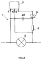
- FIG 2 there is shown another form of assembly illustrating a possible variation from the state of the art in which the two diodes mounted in opposition with a semiconductor have been replaced.
- DIAC 21 type Furthermore, a capacitor 23 is mounted by connecting the first terminal 7 to the trigger 11, downstream of the DIAC 21 semiconductor.
- the time constant is established as a function of the number of elements connected in series and of the maximum true effective voltage authorized at any time across the terminals of any element, that is to say of the number of flashed lamps that the mounting can bear.
- the capacitor charges, reaches the tripping voltage of the semiconductor 21 of the DIAC type which starts and delivers a pulse to the semiconductor 3 of the TRIAC type by capacitive discharge. If the TRIAC remains blocked, the phenomenon is repeated. If the TRIAC engages, it remains on and this until the end of the alternation.
- the behavior of the assembly is independent of the number of lamps struck in the range 0 to 4 lamps struck for 10 lamps connected in series.
- a constant supply is maintained during the time interval considered, ie 2.5 to 7.5 ms thanks to a circuit comprising a current limiting resistor 17 and two Zener diodes mounted in opposition 73.75.
- the RC circuit 25,23 whose resistance 25 is greater than the current limiting resistance 17 is supplied with a constant value so that it is always supplied with the same voltage between 4.5 and 7.5 ms.
- This device allows, by a judicious choice of the values of the components to maintain an effective tension true less than or equal to the nominal voltage of the lamps in series.
- An advantage lies in the use of inexpensive electronic components. In addition, their number is particularly reduced.
- Another advantage is that the switching is entirely static and takes place only after the correct functioning of the element 5 has been checked.
- the device of the present invention can also be associated with a means of limiting the current when the series circuit is engaged.
- a means can consist of an integrated circuit of the TDA 1024 series combined with a triac, a choke or a resistance with negative temperature coefficient (CTN), for example.
- CTN negative temperature coefficient
- the device according to the present invention is suitable for any type of series mounting.
Landscapes
- Circuit Arrangement For Electric Light Sources In General (AREA)
- Semiconductor Integrated Circuits (AREA)
- Emergency Protection Circuit Devices (AREA)
- Investigating Or Analyzing Materials By The Use Of Magnetic Means (AREA)
- Control Of Voltage And Current In General (AREA)
- Power Conversion In General (AREA)
Claims (4)
- Vorrichtung zur automatischen Wiederherstellung des Netzstroms im Falle des Durchbrennens von einem oder mehreren, zu einer Serienschaltung gehörenden Bauteilen (5), die eine Halbleiterschaltung (3) umfaßt, die parallel zu jedem Bauteil (5) der Serienschaltung gelegt ist und ein Gate (11), sowie eine mit dem Eingang des Bauteils (5) verbundene erste Klemme (7) und eine mit dem Ausgang des Bauteils (5) verbundene zweite Klemme (9) aufweist, wobei die Halbleiterschaltung (3) eingeschaltet wird und in dem leitenden Zustand gehalten wird, sobald die Spannung an ihren Klemmen (7,9) eine vorher festgelegte Spannungsschwelle zwischen ihrem Gate (11) und der zweiten Klemme (9) übersteigt, dadurch gekennzeichnet, daß die Spannungsschwelle zwischen dem Gate (11) und der zweiten Klemme (9) mittels einer Schaltung festgelegt wird, die einerseits aus einem Halbleiter von Typ DIAC (21), und andererseits aus einem RC-Glied (25,23) und zwei entgegengesetzt gerichteten Zenerdioden (73,75) besteht, wobei :- die zwei Zenerdioden (73,75) einerseits mit der ersten Klemme (7), und andererseits über einen Strombegrenzungswiderstand (17) mit der zweiten Klemme (9) verbunden sind;- das RC-Glied (25,23) mit der ersten Klemme (7) und dem Knotenpunkt zwischen dem Strombegrenzungswiderstand (17) und den Zenerdioden (73,75) verbunden ist;- und der DIAC (21) mit dem Gate (11) und dem Knotenpunkt zwischen dem Widerstand (25) und dem Kondensator (23) des RC-Glieds (25,23) verbunden ist.
- Vorrichtung gemäß Anspruch 1, dadurch gekennzeichnet, daß der Halbleiter vom Typ DIAC (21) durch zwei entgegengesetzt gerichtete Zenerdioden (13,15) ersetzt ist.
- Vorrichtung gemäß irgendeinem der vorhergehenden Ansprüche, dadurch gekennzeichnet, daß die Halbleiterschaltung (3) aus einem Halbleiter vom Typ Triac besteht.
- Vorrichtung gemäß irgendeinem der vorhergehenden Ansprüche, dadurch gekennzeichnet, daß sie einen Widerstand (19) zum Aufrechterhalten der Spannung zwischen dem Gate (11) und der ersten Klemme (7) der Halbleiterschaltung (3) aufweist.
Priority Applications (1)
| Application Number | Priority Date | Filing Date | Title |
|---|---|---|---|
| AT88870046T ATE93115T1 (de) | 1987-03-19 | 1988-03-14 | Einrichtung zum ermoeglichen der wiederherstellung des stroms einer leitung im falle des durchschlagens eines oder mehrerer elemente einer serienschaltung. |
Applications Claiming Priority (2)
| Application Number | Priority Date | Filing Date | Title |
|---|---|---|---|
| LU86815A LU86815A1 (fr) | 1987-03-19 | 1987-03-19 | Dispositif permettant le retablissement du courant de ligne en cas de claquage d'un ou de pulsieurs elements d'un montage en serie |
| LU86815 | 1987-03-19 |
Publications (2)
| Publication Number | Publication Date |
|---|---|
| EP0284592A1 EP0284592A1 (de) | 1988-09-28 |
| EP0284592B1 true EP0284592B1 (de) | 1993-08-11 |
Family
ID=19730889
Family Applications (1)
| Application Number | Title | Priority Date | Filing Date |
|---|---|---|---|
| EP88870046A Expired - Lifetime EP0284592B1 (de) | 1987-03-19 | 1988-03-14 | Einrichtung zum Ermöglichen der Wiederherstellung des Stroms einer Leitung im Falle des Durchschlagens eines oder mehrerer Elemente einer Serienschaltung |
Country Status (7)
| Country | Link |
|---|---|
| EP (1) | EP0284592B1 (de) |
| JP (1) | JPS63253858A (de) |
| AT (1) | ATE93115T1 (de) |
| CA (1) | CA1322022C (de) |
| DE (1) | DE3883042T2 (de) |
| ES (1) | ES2043892T3 (de) |
| LU (1) | LU86815A1 (de) |
Families Citing this family (13)
| Publication number | Priority date | Publication date | Assignee | Title |
|---|---|---|---|---|
| SE467132B (sv) * | 1989-09-14 | 1992-05-25 | Swedish Airport Technology Han | Faeltljusanordning |
| FR2663183B1 (fr) * | 1990-06-07 | 1997-04-11 | Fd Eclairage Architectural | Circuit d'alimentation de lampes basse tension disposees en serie. |
| NL9201189A (nl) * | 1992-07-03 | 1994-02-01 | Algra Fotometaal Bv | Serieketen, voorzien van by-pass schakelingen, alsmede daarbij te gebruiken by-pass schakeling. |
| SE9300193L (sv) * | 1992-11-20 | 1994-05-21 | Airport Tech Scandinavia | Metod och system för kommunikation från en transformators sekundärsida, särskilt för ett lampövervakningssystem för flygplatsljus |
| US5485151A (en) * | 1993-05-06 | 1996-01-16 | Adb-Alnaco, Inc. | Airfield lighting system |
| US5638057A (en) * | 1994-05-09 | 1997-06-10 | Adb-Alnaco, Inc. | Ground fault detection and measurement system for airfield lighting system |
| US5648723A (en) * | 1994-05-09 | 1997-07-15 | Adb-Alnaco, Inc. | Method and apparatus for separating and analyzing composite AC/DC waveforms |
| US7178961B2 (en) | 1995-06-26 | 2007-02-20 | Jlj, Inc. | Voltage regulated light string |
| US7732942B2 (en) | 1995-06-26 | 2010-06-08 | Jlj, Inc. | Flasher bulbs with shunt wiring for use in series connected light string with filament shunting in bulb sockets |
| US7279809B2 (en) | 1995-06-26 | 2007-10-09 | Jlj, Inc. | Christmas light string with single Zener shunts |
| US20020047594A1 (en) * | 1995-06-26 | 2002-04-25 | Janning John L. | Series connected light string with filament shunting |
| BE1009634A3 (fr) * | 1995-09-29 | 1997-06-03 | Vignisse Pierre | Dispositifs electroniques commandables par une impulsion de tension. |
| US5926115A (en) * | 1996-06-21 | 1999-07-20 | Adb Alnaco, Inc. | Airfield series circuit communications lighting system and method |
Family Cites Families (5)
| Publication number | Priority date | Publication date | Assignee | Title |
|---|---|---|---|---|
| CH427021A (de) * | 1964-07-03 | 1966-12-31 | Danfoss As | Vorrichtung zur Kompensation des Ausfalls eines Reihenwiderstandes bei einer Reihenschaltung, insbesondere bei einer Christbaumbeleuchtung |
| DE1960589A1 (de) * | 1969-12-03 | 1971-06-24 | Pintsch Bamag Ag | Einrichtung zum automatischen Einschalten des Reservefadens von Doppelfadenlampen,insbesondere in Signalanlagen |
| DE2308464A1 (de) * | 1973-02-21 | 1974-08-22 | Heinz Laass | Schutzschaltanordnung fuer elektrische geraete oder stromkreise gegen zerstoerende, ergiebige fremdspannungen |
| US3912966A (en) * | 1973-04-30 | 1975-10-14 | Gen Electric | Incandescent lamp series string having protection against voltage surges |
| DE3209186A1 (de) * | 1982-03-13 | 1983-09-15 | Licentia Patent-Verwaltungs-Gmbh, 6000 Frankfurt | Schaltungsanordnung zur begrenzung von ueberspannungen |
-
1987
- 1987-03-19 LU LU86815A patent/LU86815A1/fr unknown
-
1988
- 1988-03-14 ES ES88870046T patent/ES2043892T3/es not_active Expired - Lifetime
- 1988-03-14 EP EP88870046A patent/EP0284592B1/de not_active Expired - Lifetime
- 1988-03-14 DE DE88870046T patent/DE3883042T2/de not_active Expired - Fee Related
- 1988-03-14 AT AT88870046T patent/ATE93115T1/de not_active IP Right Cessation
- 1988-03-18 JP JP63067051A patent/JPS63253858A/ja active Pending
- 1988-03-18 CA CA000561933A patent/CA1322022C/en not_active Expired - Fee Related
Also Published As
| Publication number | Publication date |
|---|---|
| ES2043892T3 (es) | 1994-01-01 |
| EP0284592A1 (de) | 1988-09-28 |
| DE3883042D1 (de) | 1993-09-16 |
| LU86815A1 (fr) | 1988-11-17 |
| CA1322022C (en) | 1993-09-07 |
| DE3883042T2 (de) | 1993-12-02 |
| JPS63253858A (ja) | 1988-10-20 |
| ATE93115T1 (de) | 1993-08-15 |
Similar Documents
| Publication | Publication Date | Title |
|---|---|---|
| JPH11289655A (ja) | 回路遮断器 | |
| EP0284592A1 (de) | Einrichtung zum Ermöglichen der Wiederherstellung des Stroms einer Leitung im Falle des Durchschlagens eines oder mehrerer Elemente einer Serienschaltung | |
| EP0166358B1 (de) | Bedienungsorgan für eine Verbindung eines elektrischen Stromkreises mit einem Netzwerk | |
| WO2006018530A1 (fr) | Dispositif de protection contre les surtensions a capacite de coupure du courant de fuite amelioree | |
| EP0546963B1 (de) | Stromversorgungssystem mit Serien-Schutzschaltung | |
| FR2473831A1 (fr) | Appareil auxiliaire electronique pour amorcer une lampe a decharge dans un gaz et/ou dans une vapeur et faire fonctionner celle-ci sous tension alternative | |
| EP0060790A1 (de) | Fehlerstromempfindliche Ausschalter | |
| FR2493091A1 (fr) | Circuit d'amorcage et de commande pour lampes a decharge | |
| EP0085074B1 (de) | Überspannungsschutzeinrichtung für ein elektrizitätsversorgungsnetz | |
| EP0853835B1 (de) | Durch spannungsimpuls steuerbare elektrische ger äte | |
| FR2470466A1 (fr) | Dispositif de protection contre les surtensions | |
| EP0853363B1 (de) | Statischer Schalter | |
| EP0025404B1 (de) | Kurzschlusselement für Serienschaltung | |
| EP0645886B1 (de) | Hochenergiezündgenerator insbesondere für eine Gasturbine | |
| EP0063507B1 (de) | Elektronischer Starter für Fluoreszenzlampen, mit einem, mit einem Überspannungsschaltkreis und einem Vorwärmstromkreis zusammenwirkenden Zeitverzögerungsstromkreis | |
| EP0028986B1 (de) | Speisungsvorrichtung für eine Entladungslampe mit Vorheizungskreis | |
| WO1989011175A1 (fr) | Variateur de puissance de securite | |
| EP0105042A1 (de) | Vorrichtung zum Zünden einer Entladungslampe | |
| FR2492199A1 (fr) | Dispositif de reproduction d'images muni d'un tube de reproduction d'images ainsi que d'un circuit pour alimenter le filament de ce tube | |
| FR2552604A1 (fr) | Circuit de protection telephonique contre les perturbations electriques | |
| FR2737057A1 (fr) | Circuit de communication a signalisation de defaut et module de test associe | |
| FR2553961A1 (fr) | Dispositif d'allumage pour tube fluorescent a cathodes chaudes | |
| FR2594270A1 (fr) | Protection des circuits d'alimentation en serie des lampes. | |
| BE644470A (de) | ||
| FR2524219A1 (fr) | Dispositif assurant la progressivite des raccordements et des debranchements de plusieurs circuits electriques |
Legal Events
| Date | Code | Title | Description |
|---|---|---|---|
| PUAI | Public reference made under article 153(3) epc to a published international application that has entered the european phase |
Free format text: ORIGINAL CODE: 0009012 |
|
| AK | Designated contracting states |
Kind code of ref document: A1 Designated state(s): AT BE CH DE ES FR GB GR IT LI LU NL SE |
|
| 17P | Request for examination filed |
Effective date: 19890315 |
|
| 17Q | First examination report despatched |
Effective date: 19910205 |
|
| RIN1 | Information on inventor provided before grant (corrected) |
Inventor name: MAWET, JACQUES |
|
| RAP1 | Party data changed (applicant data changed or rights of an application transferred) |
Owner name: S.A. BY-PASS CONTROL |
|
| GRAA | (expected) grant |
Free format text: ORIGINAL CODE: 0009210 |
|
| AK | Designated contracting states |
Kind code of ref document: B1 Designated state(s): AT BE CH DE ES FR GB GR IT LI LU NL SE |
|
| REF | Corresponds to: |
Ref document number: 93115 Country of ref document: AT Date of ref document: 19930815 Kind code of ref document: T |
|
| GBT | Gb: translation of ep patent filed (gb section 77(6)(a)/1977) |
Effective date: 19930812 |
|
| REF | Corresponds to: |
Ref document number: 3883042 Country of ref document: DE Date of ref document: 19930916 |
|
| REG | Reference to a national code |
Ref country code: GR Ref legal event code: FG4A Free format text: 3008754 |
|
| ITF | It: translation for a ep patent filed | ||
| REG | Reference to a national code |
Ref country code: ES Ref legal event code: FG2A Ref document number: 2043892 Country of ref document: ES Kind code of ref document: T3 |
|
| EPTA | Lu: last paid annual fee | ||
| PLBE | No opposition filed within time limit |
Free format text: ORIGINAL CODE: 0009261 |
|
| STAA | Information on the status of an ep patent application or granted ep patent |
Free format text: STATUS: NO OPPOSITION FILED WITHIN TIME LIMIT |
|
| 26N | No opposition filed | ||
| EAL | Se: european patent in force in sweden |
Ref document number: 88870046.5 |
|
| PGFP | Annual fee paid to national office [announced via postgrant information from national office to epo] |
Ref country code: GB Payment date: 19960531 Year of fee payment: 9 |
|
| PGFP | Annual fee paid to national office [announced via postgrant information from national office to epo] |
Ref country code: SE Payment date: 19960618 Year of fee payment: 9 |
|
| PGFP | Annual fee paid to national office [announced via postgrant information from national office to epo] |
Ref country code: GR Payment date: 19960624 Year of fee payment: 9 |
|
| PG25 | Lapsed in a contracting state [announced via postgrant information from national office to epo] |
Ref country code: GB Effective date: 19970314 |
|
| PG25 | Lapsed in a contracting state [announced via postgrant information from national office to epo] |
Ref country code: SE Effective date: 19970315 |
|
| PGFP | Annual fee paid to national office [announced via postgrant information from national office to epo] |
Ref country code: DE Payment date: 19970318 Year of fee payment: 10 |
|
| PG25 | Lapsed in a contracting state [announced via postgrant information from national office to epo] |
Ref country code: GR Free format text: THE PATENT HAS BEEN ANNULLED BY A DECISION OF A NATIONAL AUTHORITY Effective date: 19970930 |
|
| PGFP | Annual fee paid to national office [announced via postgrant information from national office to epo] |
Ref country code: ES Payment date: 19970930 Year of fee payment: 10 Ref country code: CH Payment date: 19970930 Year of fee payment: 10 Ref country code: AT Payment date: 19970930 Year of fee payment: 10 |
|
| REG | Reference to a national code |
Ref country code: GR Ref legal event code: MM2A Free format text: 3008754 |
|
| GBPC | Gb: european patent ceased through non-payment of renewal fee |
Effective date: 19970314 |
|
| EUG | Se: european patent has lapsed |
Ref document number: 88870046.5 |
|
| PG25 | Lapsed in a contracting state [announced via postgrant information from national office to epo] |
Ref country code: AT Free format text: LAPSE BECAUSE OF NON-PAYMENT OF DUE FEES Effective date: 19980314 |
|
| PG25 | Lapsed in a contracting state [announced via postgrant information from national office to epo] |
Ref country code: ES Free format text: LAPSE BECAUSE OF EXPIRATION OF PROTECTION Effective date: 19980316 |
|
| PG25 | Lapsed in a contracting state [announced via postgrant information from national office to epo] |
Ref country code: LI Free format text: LAPSE BECAUSE OF NON-PAYMENT OF DUE FEES Effective date: 19980331 Ref country code: CH Free format text: LAPSE BECAUSE OF NON-PAYMENT OF DUE FEES Effective date: 19980331 |
|
| REG | Reference to a national code |
Ref country code: CH Ref legal event code: PL |
|
| PG25 | Lapsed in a contracting state [announced via postgrant information from national office to epo] |
Ref country code: DE Free format text: LAPSE BECAUSE OF NON-PAYMENT OF DUE FEES Effective date: 19981201 |
|
| PGFP | Annual fee paid to national office [announced via postgrant information from national office to epo] |
Ref country code: BE Payment date: 19990128 Year of fee payment: 12 |
|
| PGFP | Annual fee paid to national office [announced via postgrant information from national office to epo] |
Ref country code: NL Payment date: 19990131 Year of fee payment: 12 |
|
| PGFP | Annual fee paid to national office [announced via postgrant information from national office to epo] |
Ref country code: LU Payment date: 19990201 Year of fee payment: 12 |
|
| PGFP | Annual fee paid to national office [announced via postgrant information from national office to epo] |
Ref country code: FR Payment date: 19990317 Year of fee payment: 12 |
|
| PG25 | Lapsed in a contracting state [announced via postgrant information from national office to epo] |
Ref country code: LU Free format text: LAPSE BECAUSE OF NON-PAYMENT OF DUE FEES Effective date: 20000314 |
|
| REG | Reference to a national code |
Ref country code: ES Ref legal event code: FD2A Effective date: 20000201 |
|
| PG25 | Lapsed in a contracting state [announced via postgrant information from national office to epo] |
Ref country code: BE Free format text: LAPSE BECAUSE OF NON-PAYMENT OF DUE FEES Effective date: 20000331 |
|
| BERE | Be: lapsed |
Owner name: S.A. BY-PASS CONTROL Effective date: 20000331 |
|
| PG25 | Lapsed in a contracting state [announced via postgrant information from national office to epo] |
Ref country code: NL Free format text: LAPSE BECAUSE OF NON-PAYMENT OF DUE FEES Effective date: 20001001 |
|
| PG25 | Lapsed in a contracting state [announced via postgrant information from national office to epo] |
Ref country code: FR Free format text: LAPSE BECAUSE OF NON-PAYMENT OF DUE FEES Effective date: 20001130 |
|
| NLV4 | Nl: lapsed or anulled due to non-payment of the annual fee |
Effective date: 20001001 |
|
| REG | Reference to a national code |
Ref country code: FR Ref legal event code: ST |
|
| PG25 | Lapsed in a contracting state [announced via postgrant information from national office to epo] |
Ref country code: IT Free format text: LAPSE BECAUSE OF NON-PAYMENT OF DUE FEES;WARNING: LAPSES OF ITALIAN PATENTS WITH EFFECTIVE DATE BEFORE 2007 MAY HAVE OCCURRED AT ANY TIME BEFORE 2007. THE CORRECT EFFECTIVE DATE MAY BE DIFFERENT FROM THE ONE RECORDED. Effective date: 20050314 |