EP0284633A1 - Adaptateur à encastrer modulaire étanche à milieu de pression et sa méthode de fabrication - Google Patents
Adaptateur à encastrer modulaire étanche à milieu de pression et sa méthode de fabrication Download PDFInfo
- Publication number
- EP0284633A1 EP0284633A1 EP87104757A EP87104757A EP0284633A1 EP 0284633 A1 EP0284633 A1 EP 0284633A1 EP 87104757 A EP87104757 A EP 87104757A EP 87104757 A EP87104757 A EP 87104757A EP 0284633 A1 EP0284633 A1 EP 0284633A1
- Authority
- EP
- European Patent Office
- Prior art keywords
- sensor part
- pressure
- welding
- medium
- base body
- Prior art date
- Legal status (The legal status is an assumption and is not a legal conclusion. Google has not performed a legal analysis and makes no representation as to the accuracy of the status listed.)
- Withdrawn
Links
- 238000000034 method Methods 0.000 title claims description 10
- 238000004519 manufacturing process Methods 0.000 title claims description 5
- 238000009434 installation Methods 0.000 claims abstract description 47
- 238000003466 welding Methods 0.000 claims abstract description 46
- 238000007789 sealing Methods 0.000 claims abstract description 11
- 239000012528 membrane Substances 0.000 claims description 12
- 239000000126 substance Substances 0.000 abstract description 3
- 238000005025 nuclear technology Methods 0.000 abstract description 2
- 239000007788 liquid Substances 0.000 description 5
- 238000010276 construction Methods 0.000 description 4
- 230000006378 damage Effects 0.000 description 3
- 230000000149 penetrating effect Effects 0.000 description 3
- 238000010292 electrical insulation Methods 0.000 description 2
- 238000011156 evaluation Methods 0.000 description 2
- 239000011521 glass Substances 0.000 description 2
- 238000003780 insertion Methods 0.000 description 2
- 230000037431 insertion Effects 0.000 description 2
- 238000012545 processing Methods 0.000 description 2
- 210000004243 sweat Anatomy 0.000 description 2
- 238000005299 abrasion Methods 0.000 description 1
- 239000004020 conductor Substances 0.000 description 1
- 238000001816 cooling Methods 0.000 description 1
- 238000005260 corrosion Methods 0.000 description 1
- 230000007797 corrosion Effects 0.000 description 1
- 238000013016 damping Methods 0.000 description 1
- 238000013461 design Methods 0.000 description 1
- 238000010894 electron beam technology Methods 0.000 description 1
- 238000005516 engineering process Methods 0.000 description 1
- 238000011010 flushing procedure Methods 0.000 description 1
- 231100001261 hazardous Toxicity 0.000 description 1
- 238000011900 installation process Methods 0.000 description 1
- 238000003754 machining Methods 0.000 description 1
- 229910000679 solder Inorganic materials 0.000 description 1
- 238000012546 transfer Methods 0.000 description 1
- 238000007514 turning Methods 0.000 description 1
Images

Classifications
-
- G—PHYSICS
- G01—MEASURING; TESTING
- G01L—MEASURING FORCE, STRESS, TORQUE, WORK, MECHANICAL POWER, MECHANICAL EFFICIENCY, OR FLUID PRESSURE
- G01L19/00—Details of, or accessories for, apparatus for measuring steady or quasi-steady pressure of a fluent medium insofar as such details or accessories are not special to particular types of pressure gauges
- G01L19/14—Housings
- G01L19/142—Multiple part housings
-
- G—PHYSICS
- G01—MEASURING; TESTING
- G01L—MEASURING FORCE, STRESS, TORQUE, WORK, MECHANICAL POWER, MECHANICAL EFFICIENCY, OR FLUID PRESSURE
- G01L19/00—Details of, or accessories for, apparatus for measuring steady or quasi-steady pressure of a fluent medium insofar as such details or accessories are not special to particular types of pressure gauges
- G01L19/0061—Electrical connection means
-
- G—PHYSICS
- G01—MEASURING; TESTING
- G01L—MEASURING FORCE, STRESS, TORQUE, WORK, MECHANICAL POWER, MECHANICAL EFFICIENCY, OR FLUID PRESSURE
- G01L19/00—Details of, or accessories for, apparatus for measuring steady or quasi-steady pressure of a fluent medium insofar as such details or accessories are not special to particular types of pressure gauges
- G01L19/06—Means for preventing overload or deleterious influence of the measured medium on the measuring device or vice versa
- G01L19/0627—Protection against aggressive medium in general
- G01L19/0645—Protection against aggressive medium in general using isolation membranes, specially adapted for protection
-
- G—PHYSICS
- G01—MEASURING; TESTING
- G01L—MEASURING FORCE, STRESS, TORQUE, WORK, MECHANICAL POWER, MECHANICAL EFFICIENCY, OR FLUID PRESSURE
- G01L19/00—Details of, or accessories for, apparatus for measuring steady or quasi-steady pressure of a fluent medium insofar as such details or accessories are not special to particular types of pressure gauges
- G01L19/14—Housings
- G01L19/148—Details about the circuit board integration, e.g. integrated with the diaphragm surface or encapsulation
Definitions
- the invention relates to an installation adapter for a pressure transducer, in particular a pressure transmitter, for measuring the pressure in a flow medium, and to a method for its production.
- the invention relates in particular to a built-in adapter and a pressure transducer equipped therewith, the amplifier electronics of which are electrically connected to the sensor part of the built-in adapter, which is distinguished by a special tightness with respect to the pressure medium.
- pressure transducers are known, both on a piezoelectric as well as on a piezoresistive basis, and also of pressure transmitters in which the electronic signal evaluation is either partially or completely integrated into the transducer.
- a pressure transmitter consists of a pressure-absorbing membrane, a pressure-transmitting medium, for.
- B. oil for example a piezoresistive measuring cell with electrical supply and discharge lines, a coupled electronic part for signal processing and a plug for the electrical connection to the outside.
- the parts listed can be in a single closed housing that is screwed into the thread of a pipe or housing that contains the medium whose pressure is to be measured.
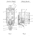
- FIG. 1 a modular structure of the pressure transmitter described is advantageous in that the most diverse installation needs - installation sockets of different lengths, with different diameters, different thread types, etc. - because they can be satisfied in a more rational way.
- a modular structure (FIG. 1) consists of an electronics housing with a casing and a cover plate with a plug connection, base plate with a bore and thread for receiving the installation adapter, which also contains the sensor part shown in detail in FIG. 2.
- the installation adapter On the side of the pressure medium, the installation adapter is provided with a threaded connector that is adapted to the installation requirements.
- the modular structure described above represents the customary prior art and is illustrated by FIGS. 1 and 2.
- Fig. 1 shows a modular pressure transmitter
- Fig. 2 shows the sensor part as a detail, in the form of a modular piezoresistive measuring cell.
- 1 means the installation adapter or its base body, 2 the sensor part and 3 the electronics part.
- the installation adapter 1 contains, in the part facing the electronics part 3, the sensor part 2, which is sealed with a sealing ring 4, which is intended to prevent the gaseous or liquid medium to be measured from penetrating into the electronics part 3.
- the installation adapter 1 is screwed into the base plate 6 of the electronic part 3, the longitudinal extent of the sensor part 2 being able to be dimensioned such that, using a further sealing ring 7, the sensor part is pretensioned during installation between said sealing ring and stop 8 can.
- the membrane part 9 of the sensor part absorbs the pressure that the medium exerts through the pressure channel 10 of the installation adapter 1.
- the installation adapter 1 supports its section facing the medium, an installation socket 11 with an installation thread 12, which can be installed in a corresponding (not shown in the drawing) threaded hole in the housing or pipe.
- the main advantage of the modular construction lies in the fact that the socket 11 is dimensioned differently and the installation thread 12 is configured differently and can therefore meet the most varied installation requirements.
- the electronics part 3 adjoining the installation adapter 1 and the sensor part essentially contains a mounting plate 13 which is equipped with electronic components. The electronics integrated in this way in the pressure transmitter are used for signal evaluation and processing, the electrical signals from the sensor part 2 being fed to the electronics through wire-shaped signal feeds 14 and the processed signals are fed via the same signal leads 15 to a plug 17 screwed into the cover plate 16.
- Base plate 6, cover plate 16 and housing jacket 28 together form the hermetically sealed electronic part 3.
- FIG. 2 shows a detail from FIG. 1, the seal against the pressure medium being made visible in the main.
- the numbers have the same meaning as before. 1 thus means the installation adapter shown in its inner limitation, 2 the sensor part, which is shown on the left side of the figure in longitudinal section, on the right side in side view, 4 and 7 the sealing rings, 9 the membrane and 14 an electrical signal derivative.
- the electrical insulation 18 (mostly glass) of the signal lead 14, the pressure-transmitting insulating liquid 20 and the piezoresistive measuring element 21 are newly drawn.
- Figures 1 and 2 represent the prior art, which is characterized by the modular structure of the pressure transmitter and the sealing of the electronic part from the liquid or gaseous pressure medium by sealing rings.
- the figures show certain embodiments, for example characterized in that the sensor part with the membrane is not shown in the front of the installation adapter, but in a rear area. At low pressures, non-aggressive and not too hot pressure media, the sensor part with membrane can also be attached to the front of the installation adapter.
- the type of seal described and shown in FIGS. 1 and 2 is sufficient to prevent the pressure medium from penetrating into the sensitive electronic part.
- the seals which are usually designed as O-rings, that when the pressure changes, which acts on the membrane, in particular at pulsating pressure, these rings move, deform and are exposed to abrasion on their relatively rough surface, which they leaks and allows the more or less aggressive medium to pass through ("leakage").
- the attack on the rings can also be supported by high and changing temperatures and by the chemical aggressiveness of certain media.
- the pressure medium then comes into contact with the electronic components, the conductor tracks and solder joints and destroys the functionality of the electronic part through corrosion.
- the previous type of seal is therefore unsuitable for applications that require high operational reliability.
- An installation adapter for a pressure sensor for measuring the pressure in a flow medium with a base body having a passage passage, in which a sensor part exposed to the medium is received at one end for the delivery of an electrical signal corresponding to the medium pressure, and with a seal between the sensor part and the base body are characterized in that opposite, essentially annular end face regions of the sensor part and of the base body are connected to one another in a medium-tight manner by butt welding.
- One of the end surface areas can be a heel surface provided in the base body, which is assigned an end face of the sensor part that faces or faces away from the medium.
- a prestressing device can be provided in order to exert a prestressing force on the butt weld on the end of the sensor part facing away from the weld.
- a membrane section of the sensor part can be flush with the end face of the adapter or set back from the end face.
- a gap present between the sensor part and the base body can be sealed by an O-ring arranged in one of the two parts.
- the method according to the invention for producing such a mounting adapter is characterized in that the sensor part or the base body or both is provided with at least one extensive increase in welding, and that when the sensor part is mounted in the base body, at least one flat end face region on either the sensor part or base body is provided with an opposite one Increasing sweat on the other part in question is brought into contact, and that at least one of the at most two pairs formed on opposite sides of the sensor part is made of flat end face regions and sweat increases, a medium-density resistance welding.
- the welding elevations preferably have a hump-like design in cross section. It is particularly advantageous if increases in welding are provided on both opposite end faces of the sensor part. This creates a modular installation adapter that enables universal mounting on the pressure transmitter. If desired, however, at least one of the weld pairs can also comprise an increase in weld on a heel surface of the base body, which is accordingly to be assigned a flat end face region (without increase in weld) on the sensor part.
- the welding can be carried out on the side of the sensor part facing or facing away from the medium, wherein a pretensioning force can be exerted on the welding in order to achieve a particularly high pressure tightness of the welding point. To avoid electrical flashovers during welding, you can place between the sensor part and the body an insulating gap can be maintained by a centering aid in the form of an O-ring or the like.
- the invention further relates to a pressure transmitter equipped with a previously described installation adapter.
- Figures 3, 4, 5 represent the central concern of the invention, which consists in making the seal against the pressure medium (not shown in the drawings) no longer by unreliable sealing rings, but by annular welds between the sensor part and installation adapter.
- the illustrated embodiments all relate to a pressure transmitter with a piezoresistive transducer element.
- the invention can also be applied to embodiments with piezoelectric or other transducer elements.
- the installation adapter, the position of the sensor part and the position of the welding are designed differently.
- the numbers designate functionally identical parts and mean the same as before.
- FIG 3 shows a pressure transmitter with a built-in adapter with a recessed sensor part 2.
- This embodiment is used, for example, at higher pressures, at which a built-in connector 11 with a relatively small diameter is selected, so that the acting forces do not become too great. It is then indicated for reasons of space to accommodate the sensor part 2 in a rear area of the installation adapter 1.
- This position of the sensor part 2 can also be advantageous in the case of hot media, because the temperature-sensitive parts of the pressure transmitter, such as the electrical insulation, are then exposed to a lower temperature.
- the sensor part 2 is inserted into the mounting adapter 1 through a rear bore with a thread 23 up to a stop 8.
- the sensor part 2 has already been pre-checked before the installation process and has been provided, for example, with a front and a rear circumferential weld increase in the form of, for example, a ring hump.
- the details of its manufacture will be discussed in more detail later.
- the sealing ring 4 lying in a groove (in the present example an O-ring) facilitates a centered insertion of the sensor part 2 and is dimensioned in such a way that it has a radial distance between the walls of the bore and the sensor part 2 that is uniform on all sides and sufficient for the subsequent resistance welding guaranteed and an electrical flashover prevented.
- the frontal welding in the case of FIG.
- FIG. 3 shows a preloaded threaded ring 22 which fits into an internal thread 23 in the upper part of the bore in the mounting adapter 1, with the help of which the front weld 24 of the sensor part 2 can be placed under a mechanical pressure stress, which means that even in continuous operation very high, possibly additionally pulsating pressures can be measured without the pressure medium in the electronic part 3 can penetrate.
- the further construction of the pressure transmitter corresponds to FIG. 1, apart from the fact that the electronic part 3 does not require a base plate (number 6 in FIG. 1), since the housing jacket 18 is directly connected to the mounting adapter 1 over the entire circumference.
- FIG. 4 shows an embodiment of a pressure transmitter according to the invention, in which the sensor part 2 is accommodated on the medium side in the installation adapter 1, as a result of which the pressure medium acts directly on the sensor part 2 and the pressure channel 10 is omitted.
- This embodiment is used for example at low pressures.
- the sensor part 2 is inserted from the front, ie from the medium side, into a bore in the mounting socket 11, the sealing ring 4 (O-ring) in turn acting in a centering manner and producing a radial spacing of the walls of the sensor part 2 and the mounting socket 11 that is necessary in terms of welding technology .
- the welding takes place here on the back of the sensor part 2, between this part and its rear stop and is again a resistance welding (butt welding).
- the rest of the structure of the pressure transmitter corresponds to that of FIG. 3, only the possibility of prestressing by means of a prestressing threaded ring (number 22 in FIG. 3) being missing.
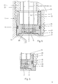
- FIG. 5 shows the sensor part 2 used in FIGS. 3 and 4 and the welding possibilities in more detail.
- a sensor based on the piezoresistive principle is shown with a membrane 9, which transmits the pressure via a liquid 20 to the piezoresistive transducer element 26.
- the liquid that also fills the annular gap 27 must be electrically insulating, e.g. an oil because it contains signal lines 14 with lead wires 28.
- the left side of the figure shows the installation and welding of the sensor part 2 according to FIG. 3, i.e. with recessed sensor part, the right side shows the installation and the welding of the mentioned part according to Fig. 4, i.e. with sensor part 2 installed at the front. On the left side, the welding takes place frontally, 24, on the right side at the rear, 25, as mentioned in the description of FIGS. 3 and 4.
- the sensor part 2 is a pre-tested, ready-to-install module. This also means that the points that need to be welded are prepared for welding. For this reason, ring-shaped welding bosses are attached to both the front and the back of the sensor part. These can either be produced by machining operations (eg turning) on the front and back or by applying ring-shaped, weldable or solderable masses in a hump shape, which can be done, for example, by electron beam welding. The diameters of these weldable rings are, of course, different depending on the application and can nor be lubricated. Conical welding bosses are suitable, but others, for example semicircular ones, can also be used.
- the membrane section 9 is shown flush with the inner wall of a pressure vessel or pressure pipe, corresponding to FIG. 4.
- FIG. 4 there are applications where flushing is not necessary and may not be desirable.
- Moving the sensor part 2 back creates a free space that can be used, for example, to accommodate damping and cooling elements or, in the case of particle-carrying media, prevents damage to the membrane part 9.
- FIG. 6 shows an embodiment according to the invention which prevents the pressure medium from penetrating into the - narrow - gap between sensor part 2 and mounting socket 11 of the mounting adapter, as is the case with the embodiment with rear welding according to FIG. 4 or according to the right side of FIG. 5 is possible to a limited extent.
- This is achieved by a rear frontal weld 30.
- the frontal circumferential part of the sensor body 29 is expanded to a flange 31 on which an annular welding boss is attached. This means that the gap mentioned can be frontal, i.e. are sealed on the medium side by resistance welding, which is carried out analogously to the previous cases.
- the creation of a hermetically sealed weld connection between the sensor part 2 and the installation adapter 1 in a pressure transmitter increases its operational safety to a decisive extent by the sens Lichen parts of the transmitter, such as the electronic part, are protected from damage or destruction by the pressure medium.
- Such sensitive parts also exist in a pressure sensor, so that the invention also includes pressure sensors.
- Maximum operational safety is required, for example, by braking systems in road and rail traffic, but also when the pressure medium is environmentally hazardous, such as in nuclear technology or in the chemical industry.
- the parts prepared for butt welding preferably ring bosses
- the ring bosses can also be applied on the opposite side, that is to say on the installation adapter.
Landscapes
- Physics & Mathematics (AREA)
- General Physics & Mathematics (AREA)
- Measuring Fluid Pressure (AREA)
Priority Applications (1)
| Application Number | Priority Date | Filing Date | Title |
|---|---|---|---|
| EP87104757A EP0284633A1 (fr) | 1987-03-31 | 1987-03-31 | Adaptateur à encastrer modulaire étanche à milieu de pression et sa méthode de fabrication |
Applications Claiming Priority (1)
| Application Number | Priority Date | Filing Date | Title |
|---|---|---|---|
| EP87104757A EP0284633A1 (fr) | 1987-03-31 | 1987-03-31 | Adaptateur à encastrer modulaire étanche à milieu de pression et sa méthode de fabrication |
Publications (1)
| Publication Number | Publication Date |
|---|---|
| EP0284633A1 true EP0284633A1 (fr) | 1988-10-05 |
Family
ID=8196884
Family Applications (1)
| Application Number | Title | Priority Date | Filing Date |
|---|---|---|---|
| EP87104757A Withdrawn EP0284633A1 (fr) | 1987-03-31 | 1987-03-31 | Adaptateur à encastrer modulaire étanche à milieu de pression et sa méthode de fabrication |
Country Status (1)
| Country | Link |
|---|---|
| EP (1) | EP0284633A1 (fr) |
Cited By (16)
| Publication number | Priority date | Publication date | Assignee | Title |
|---|---|---|---|---|
| EP0915326A1 (fr) * | 1997-10-10 | 1999-05-12 | WIKA ALEXANDER WIEGAND GmbH & CO. | Procédé de fabrication d'un capteur de pression et capteur de pression |
| WO2004053449A1 (fr) * | 2002-12-12 | 2004-06-24 | Danfoss A/S | Capteur de pression |
| EP1099095A4 (fr) * | 1998-07-22 | 2004-07-28 | Ssi Technologies Inc | Ensemble capteur a connexion flottante |
| DE102005053062A1 (de) * | 2005-11-04 | 2007-05-10 | Ifm Electronic Gmbh | Drucksensor |
| DE102006033467A1 (de) * | 2006-07-19 | 2008-01-31 | Siemens Ag | Druckerfassungsvorrichtung |
| EP1724562A3 (fr) * | 2005-05-20 | 2009-12-23 | Emerson Climate Technologies, Inc. | Capteur de pression pour machine hermétique |
| DE19936300B4 (de) * | 1998-08-04 | 2010-01-21 | DENSO CORPORATION, Kariya-shi | Druckerkennungsvorrichtung und Druckerkennungsvorrichtung-Anordnung hiermit |
| WO2011047919A1 (fr) * | 2009-10-19 | 2011-04-28 | Robert Bosch Gmbh | Capteur de pression, en particulier pour dispositifs de freinage |
| US8262372B2 (en) | 2007-05-10 | 2012-09-11 | Emerson Climate Technologies, Inc. | Compressor hermetic terminal |
| US8939735B2 (en) | 2009-03-27 | 2015-01-27 | Emerson Climate Technologies, Inc. | Compressor plug assembly |
| US8939734B2 (en) | 2007-08-28 | 2015-01-27 | Emerson Climate Technologies, Inc. | Molded plug for a compressor |
| US9480177B2 (en) | 2012-07-27 | 2016-10-25 | Emerson Climate Technologies, Inc. | Compressor protection module |
| DE102007035013B4 (de) * | 2006-08-18 | 2017-01-12 | General Electric Technology Gmbh | Sensoranordnung zur Messung von hochfrequenten Drucksignalen in einer Brennkammer |
| CN109540353A (zh) * | 2018-11-14 | 2019-03-29 | 李世超 | 一种压力传感器的生产工艺 |
| DE102019209031A1 (de) * | 2019-06-21 | 2020-12-24 | Metallux Ag | Drucksensoreinrichtung |
| CN117782258A (zh) * | 2024-02-26 | 2024-03-29 | 山东亿格其工业自动化技术有限公司 | 一种具有密封结构的液位变送器 |
Citations (2)
| Publication number | Priority date | Publication date | Assignee | Title |
|---|---|---|---|---|
| DE1955178A1 (de) * | 1969-01-18 | 1972-01-05 | Naue Kg E A H | Durch Schaumstoff-Flocken veredelter Torf und Fertigerde |
| DE2801677A1 (de) * | 1978-01-16 | 1979-07-19 | Hydrotechnik Gmbh | Vorrichtung zur druckmessung |
-
1987
- 1987-03-31 EP EP87104757A patent/EP0284633A1/fr not_active Withdrawn
Patent Citations (2)
| Publication number | Priority date | Publication date | Assignee | Title |
|---|---|---|---|---|
| DE1955178A1 (de) * | 1969-01-18 | 1972-01-05 | Naue Kg E A H | Durch Schaumstoff-Flocken veredelter Torf und Fertigerde |
| DE2801677A1 (de) * | 1978-01-16 | 1979-07-19 | Hydrotechnik Gmbh | Vorrichtung zur druckmessung |
Cited By (26)
| Publication number | Priority date | Publication date | Assignee | Title |
|---|---|---|---|---|
| US6105437A (en) * | 1997-10-10 | 2000-08-22 | Wika Alexander Wiegand Gmbh & Co. | Pressure transducer |
| EP0915326A1 (fr) * | 1997-10-10 | 1999-05-12 | WIKA ALEXANDER WIEGAND GmbH & CO. | Procédé de fabrication d'un capteur de pression et capteur de pression |
| EP1099095A4 (fr) * | 1998-07-22 | 2004-07-28 | Ssi Technologies Inc | Ensemble capteur a connexion flottante |
| DE19936300B4 (de) * | 1998-08-04 | 2010-01-21 | DENSO CORPORATION, Kariya-shi | Druckerkennungsvorrichtung und Druckerkennungsvorrichtung-Anordnung hiermit |
| WO2004053449A1 (fr) * | 2002-12-12 | 2004-06-24 | Danfoss A/S | Capteur de pression |
| US7311007B2 (en) | 2002-12-12 | 2007-12-25 | Danfoss A/S | Pressure sensor |
| US7866964B2 (en) | 2005-05-20 | 2011-01-11 | Emerson Climate Technologies, Inc. | Sensor for hermetic machine |
| EP1724562A3 (fr) * | 2005-05-20 | 2009-12-23 | Emerson Climate Technologies, Inc. | Capteur de pression pour machine hermétique |
| KR101203004B1 (ko) | 2005-05-20 | 2012-11-20 | 에머슨 클리메이트 테크놀로지즈 인코퍼레이티드 | 밀폐식 머신용 센서 |
| DE102005053062A1 (de) * | 2005-11-04 | 2007-05-10 | Ifm Electronic Gmbh | Drucksensor |
| DE102005053062B4 (de) * | 2005-11-04 | 2011-02-10 | Ifm Electronic Gmbh | Drucksensor |
| DE102006033467A1 (de) * | 2006-07-19 | 2008-01-31 | Siemens Ag | Druckerfassungsvorrichtung |
| DE102006033467B4 (de) * | 2006-07-19 | 2010-03-25 | Continental Automotive Gmbh | Druckerfassungsvorrichtung |
| US7827867B2 (en) | 2006-07-19 | 2010-11-09 | Continental Automotive Gmbh | Pressure sensing device |
| DE102007035013B4 (de) * | 2006-08-18 | 2017-01-12 | General Electric Technology Gmbh | Sensoranordnung zur Messung von hochfrequenten Drucksignalen in einer Brennkammer |
| US8262372B2 (en) | 2007-05-10 | 2012-09-11 | Emerson Climate Technologies, Inc. | Compressor hermetic terminal |
| US8939734B2 (en) | 2007-08-28 | 2015-01-27 | Emerson Climate Technologies, Inc. | Molded plug for a compressor |
| US8939735B2 (en) | 2009-03-27 | 2015-01-27 | Emerson Climate Technologies, Inc. | Compressor plug assembly |
| WO2011047919A1 (fr) * | 2009-10-19 | 2011-04-28 | Robert Bosch Gmbh | Capteur de pression, en particulier pour dispositifs de freinage |
| US9480177B2 (en) | 2012-07-27 | 2016-10-25 | Emerson Climate Technologies, Inc. | Compressor protection module |
| US10028399B2 (en) | 2012-07-27 | 2018-07-17 | Emerson Climate Technologies, Inc. | Compressor protection module |
| US10485128B2 (en) | 2012-07-27 | 2019-11-19 | Emerson Climate Technologies, Inc. | Compressor protection module |
| CN109540353A (zh) * | 2018-11-14 | 2019-03-29 | 李世超 | 一种压力传感器的生产工艺 |
| DE102019209031A1 (de) * | 2019-06-21 | 2020-12-24 | Metallux Ag | Drucksensoreinrichtung |
| CN117782258A (zh) * | 2024-02-26 | 2024-03-29 | 山东亿格其工业自动化技术有限公司 | 一种具有密封结构的液位变送器 |
| CN117782258B (zh) * | 2024-02-26 | 2024-05-10 | 山东亿格其工业自动化技术有限公司 | 一种具有密封结构的液位变送器 |
Similar Documents
| Publication | Publication Date | Title |
|---|---|---|
| EP0284633A1 (fr) | Adaptateur à encastrer modulaire étanche à milieu de pression et sa méthode de fabrication | |
| DE60018962T2 (de) | Vorinstallation eines drucksensormoduls | |
| EP1269135B1 (fr) | Module de detection de pression | |
| EP1167938B1 (fr) | Dispositif de mesure de pression | |
| EP1327128B1 (fr) | Dispositif de mesure de pression | |
| EP0594808B1 (fr) | Dispositif permettant de mesurer la pression et la pression differentielle avec une boite filetee en trois parties et une corniere annulaire | |
| EP1396718B1 (fr) | Capteur électrochimique | |
| DE4234290C2 (de) | Drucksensor | |
| EP1169202A1 (fr) | Dispositif pour mesurer une pression de fluide | |
| DE2628667A1 (de) | Verfahren und vorrichtung zum befestigen der mittelelektrode in einem keramischen zuendkerzen-isolator | |
| EP0756699A1 (fr) | Capteur ou detecteur de pression piezoresistif | |
| DE19608310C1 (de) | Differenzdruckmeßumformereinheit mit einem Überlastschutzsystem | |
| EP2359098B1 (fr) | Convertisseur de mesure de pression différentielle | |
| WO1999030943A1 (fr) | Systeme de freinage | |
| EP4070061A1 (fr) | Procédé de production d'un capteur de pression différentielle | |
| DE19933256A1 (de) | Anschlussstutzen und Gehäuse, insbesondere Kraftstoffhochdruckspeicher, mit vorgespannt angeschweißtem Anschlussstutzen für ein Kraftstoffeinspritzsystem für Brennkraftmaschinen | |
| EP0660482A1 (fr) | Dispositif pour la traversée étanche d'un câble | |
| CH394637A (de) | Verfahren zur Herstellung eines piezoelektrischen Messwandlers | |
| DE4315962C2 (de) | Kapsel für einen Drucksensor und Verfahren zur Einkapselung desselben | |
| EP1334343A1 (fr) | Capteur de pression et son procede de montage | |
| DE102017122244A1 (de) | Druckerfassungsvorrichtung, damit ausgestatteter Verbrennungsmotor und Verfahren zu deren Herstellung | |
| WO2022128399A1 (fr) | Transducteur de pression coplanaire pour détermination de valeur de mesure de pression d'un milieu | |
| DE10327476A1 (de) | Drucksensor-Anordnung | |
| DE1236827C2 (de) | Piezoelektrischer Druckwandler sowie Verfahren und Vorrichtung zu seiner Montage | |
| WO2022037859A1 (fr) | Capteur de pression différentielle pour détermination de la pression différentielle entre deux pressions |
Legal Events
| Date | Code | Title | Description |
|---|---|---|---|
| PUAI | Public reference made under article 153(3) epc to a published international application that has entered the european phase |
Free format text: ORIGINAL CODE: 0009012 |
|
| AK | Designated contracting states |
Kind code of ref document: A1 Designated state(s): AT CH DE FR GB LI |
|
| STAA | Information on the status of an ep patent application or granted ep patent |
Free format text: STATUS: THE APPLICATION IS DEEMED TO BE WITHDRAWN |
|
| 18D | Application deemed to be withdrawn |
Effective date: 19890406 |
|
| RIN1 | Information on inventor provided before grant (corrected) |
Inventor name: VOLLENWEIDER, KURT WALTER Inventor name: WENGER, ALFRED, DR. PHYS. Inventor name: CALDERARA, RETO, DIPL.-CHEM. Inventor name: SONDEREGGER, HANS CONRAD, DIPL.-ING. |