EP0284673A2 - Brûleur pour un combustible gazeux - Google Patents
Brûleur pour un combustible gazeux Download PDFInfo
- Publication number
- EP0284673A2 EP0284673A2 EP87201981A EP87201981A EP0284673A2 EP 0284673 A2 EP0284673 A2 EP 0284673A2 EP 87201981 A EP87201981 A EP 87201981A EP 87201981 A EP87201981 A EP 87201981A EP 0284673 A2 EP0284673 A2 EP 0284673A2
- Authority
- EP
- European Patent Office
- Prior art keywords
- burner
- supply conduit
- wall
- box
- mixing
- Prior art date
- Legal status (The legal status is an assumption and is not a legal conclusion. Google has not performed a legal analysis and makes no representation as to the accuracy of the status listed.)
- Granted
Links
Images

Classifications
-
- F—MECHANICAL ENGINEERING; LIGHTING; HEATING; WEAPONS; BLASTING
- F23—COMBUSTION APPARATUS; COMBUSTION PROCESSES
- F23D—BURNERS
- F23D14/00—Burners for combustion of a gas, e.g. of a gas stored under pressure as a liquid
- F23D14/12—Radiant burners
- F23D14/16—Radiant burners using permeable blocks
-
- F—MECHANICAL ENGINEERING; LIGHTING; HEATING; WEAPONS; BLASTING
- F23—COMBUSTION APPARATUS; COMBUSTION PROCESSES
- F23D—BURNERS
- F23D14/00—Burners for combustion of a gas, e.g. of a gas stored under pressure as a liquid
- F23D14/46—Details
- F23D14/62—Mixing devices; Mixing tubes
-
- F—MECHANICAL ENGINEERING; LIGHTING; HEATING; WEAPONS; BLASTING
- F23—COMBUSTION APPARATUS; COMBUSTION PROCESSES
- F23D—BURNERS
- F23D2212/00—Burner material specifications
- F23D2212/20—Burner material specifications metallic
- F23D2212/201—Fibres
-
- F—MECHANICAL ENGINEERING; LIGHTING; HEATING; WEAPONS; BLASTING
- F23—COMBUSTION APPARATUS; COMBUSTION PROCESSES
- F23D—BURNERS
- F23D2213/00—Burner manufacture specifications
Definitions
- the present invention relates to a burner for a gaseous fuel comprising a distributing zone surrounded by an outer wall consisting at least partly of a porous medium.
- a device for introducing a pre-mixed fuel/oxidant mixture is in general so constructed that the fuel/oxidant mixture introduced into the distributing zone is evenly distributed over the inside of the wall of porous medium.
- the burner for a gaseous fuel comprises a distributing zone surrounded by an outer wall consisting at least partly of a porous medium, an oxidant supply conduit debouching in the distributing zone, a fuel supply conduit, and a mixing head arranged in the oxidant supply conduit, which mixing head comprises a box in which the fuel supply conduit debouches and open-ended mixing tubes which extend through the box, wherein the part of the wall of a mixing tube located in the box is provided with openings.
- FIG. 1 shows a burner 1 for a gaseous fuel comprising a distributing zone 2 surrounded by an outer wall 3.
- the outer wall 3 comprises a circle cylindrical part 4 consisting of a porous medium and an impermeable end wall 5 joined to the cylindrical part 4.
- the cylindrical part is joined to a base plate 6.
- the burner 1 further comprises an oxidant supply conduit 9 debouching in the distributing zone 2, a fuel supply conduit 12, and a mixing head 13 arranged in the oxidant supply conduit 9.
- the mixing head 13 comprises a box 15 in which the fuel supply conduit 12 debouches.
- the box 15 comprises an end plate 17 provided with openings 20 and an end plate 18 provided with openings 21 located opposite to openings 20.
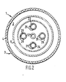
- the mixing head 13 further comprises four open-ended mixing tubes 23, 24, 25 and 26 which extend through the openings 20 and 21.
- the mixing tubes 23, 24, 25 and 26 extend through the box 15, and the part of the wall of each mixing tube 23, 24, 25 or 26 located in the box 15 is provided with openings 29.
- mixing tube 26 is not shown in Figure 1, and not all openings in the part of the wall of the mixing tubes located in the box have been indicated with reference numerals.
- a gaseous fuel is supplied to the mixing head 13 through the fuel supply conduit 12, and oxidant is supplied through conduit 31 to the oxidant supply conduit 9.
- the gaseous fuel flows into the interior of the box 15, and from there through the openings 29 into the open-ended mixing tubes 23, 24, 25 and 26.
- a part of the oxidant supplied to the oxidant supply conduit 9 flows through the open-ended mixing tubes 23, 24, 25 and 26 and entrains the gaseous fuel so that a thoroughly mixed fuel/oxidant mixture is produced.
- the fuel/oxidant mixture flows out of the mixing tubes 23, 24, 25 and 26 into the annular space between the oxidant supply conduit 9 and the circle cylindrical part 4 of the outer wall 3 which part consists of a porous medium.
- the mixture is ignited by means of an ignition device (not shown) arranged near the outer surface of the cylindrical wall part 4, and the mixture burns in the outer layers of the cylindrical wall part 4.
- An advantage of this embodiment is that the fuel/oxidant mixture cools the impermeable end wall 5.
- a further advantage of the burner according to the invention is that the mixing device is located in a zone which is otherwise wasted.
- the burner according to the invention only part of the inner space of the burner is filled with a combustible fuel/oxidant mixture.
- the opening of the oxidant supply tube nay be provided with a flow restriction in the form of a ring 33.
- the outer wall of the box 15 may be provided with openings 36 through which oxidant can flow into the box to be mixed with fuel in the box 15.
- impermeable end wall 5 is replaced by a wall of porous medium so that the burner can be used for space heating.
- the gaseous fuel for the burner according to the invention may be any gaseous fuel, for example natural gas, synthesis gas or refinery gas.
- the oxidant is a free oxygen-containing gas such as air.
- the ratio of the diameter of the oxidant supply conduit 9 and the diameter of the distributing zone 2 is between 0.6 and 0.8.
- the ratio of the diameter of the mixing head 13 and the diameter of the oxidant supply conduit 9 may be selected between 0.8 and 1 in which case part of the wall of conduit 9 forms the outer wall of the mixing head 13.
- the ratio of the length of the oxidant supply conduit 9 and the length of the distributing zone 2 is suitably between 0.7 and 0.9.
- the distributing zone 2 may as well have a square cross-section or a rectangular cross-section.
- the porous medium may comprise sintered metal fibres, porous ceramic material or other suitable materials.
Landscapes
- Engineering & Computer Science (AREA)
- Chemical & Material Sciences (AREA)
- Combustion & Propulsion (AREA)
- Mechanical Engineering (AREA)
- General Engineering & Computer Science (AREA)
- Gas Burners (AREA)
Applications Claiming Priority (2)
| Application Number | Priority Date | Filing Date | Title |
|---|---|---|---|
| GB868624632A GB8624632D0 (en) | 1986-10-14 | 1986-10-14 | Burner for gaseous fuel |
| GB8624632 | 1986-10-14 |
Publications (3)
| Publication Number | Publication Date |
|---|---|
| EP0284673A2 true EP0284673A2 (fr) | 1988-10-05 |
| EP0284673A3 EP0284673A3 (en) | 1989-02-15 |
| EP0284673B1 EP0284673B1 (fr) | 1991-01-09 |
Family
ID=10605735
Family Applications (1)
| Application Number | Title | Priority Date | Filing Date |
|---|---|---|---|
| EP87201981A Expired - Lifetime EP0284673B1 (fr) | 1986-10-14 | 1987-10-14 | Brûleur pour un combustible gazeux |
Country Status (8)
| Country | Link |
|---|---|
| US (1) | US4746286A (fr) |
| EP (1) | EP0284673B1 (fr) |
| JP (1) | JP2534077B2 (fr) |
| AU (1) | AU593393B2 (fr) |
| CA (1) | CA1291022C (fr) |
| DE (1) | DE3767302D1 (fr) |
| ES (1) | ES2021020B3 (fr) |
| GB (1) | GB8624632D0 (fr) |
Families Citing this family (6)
| Publication number | Priority date | Publication date | Assignee | Title |
|---|---|---|---|---|
| US5017129A (en) * | 1990-02-06 | 1991-05-21 | Scheu Manufacturing Company | Porous ceramic gas burner |
| US5688115A (en) * | 1995-06-19 | 1997-11-18 | Shell Oil Company | System and method for reduced NOx combustion |
| US6051180A (en) * | 1998-08-13 | 2000-04-18 | Illinois Tool Works Inc. | Extruding nozzle for producing non-wovens and method therefor |
| TWI450439B (zh) | 2009-10-22 | 2014-08-21 | Atomic Energy Council | 應用於高溫燃料電池之多孔性介質燃燒器 |
| US9599343B2 (en) * | 2012-11-28 | 2017-03-21 | General Electric Company | Fuel nozzle for use in a turbine engine and method of assembly |
| JP6551375B2 (ja) * | 2016-12-07 | 2019-07-31 | トヨタ自動車株式会社 | 水素ガスバーナ構造およびこれを備えた水素ガスバーナ装置 |
Family Cites Families (5)
| Publication number | Priority date | Publication date | Assignee | Title |
|---|---|---|---|---|
| US3425675A (en) * | 1966-12-14 | 1969-02-04 | Alco Standard Corp | Burner tube assembly for heat treating furnace |
| US3731668A (en) | 1971-05-19 | 1973-05-08 | Impala Ind Inc | Catalytic heater |
| US3822986A (en) * | 1973-06-07 | 1974-07-09 | A Tsekhovoi | Gas distribution grid |
| GB2054822B (en) * | 1979-06-15 | 1983-04-07 | Urquhart Eng Co Ltd | Controlled combustion of gases |
| DE3102742A1 (de) * | 1980-02-04 | 1982-01-14 | Franz Ing. 1140 Wien Lindmayr | "durch einen mit gas betriebenen brenner beheiztes geraet" |
-
1986
- 1986-10-14 GB GB868624632A patent/GB8624632D0/en active Pending
-
1987
- 1987-07-29 US US07/078,952 patent/US4746286A/en not_active Expired - Lifetime
- 1987-09-24 CA CA000547700A patent/CA1291022C/fr not_active Expired - Lifetime
- 1987-10-12 JP JP62254827A patent/JP2534077B2/ja not_active Expired - Lifetime
- 1987-10-12 AU AU79549/87A patent/AU593393B2/en not_active Expired
- 1987-10-14 ES ES87201981T patent/ES2021020B3/es not_active Expired - Lifetime
- 1987-10-14 DE DE8787201981T patent/DE3767302D1/de not_active Expired - Lifetime
- 1987-10-14 EP EP87201981A patent/EP0284673B1/fr not_active Expired - Lifetime
Also Published As
| Publication number | Publication date |
|---|---|
| JP2534077B2 (ja) | 1996-09-11 |
| AU593393B2 (en) | 1990-02-08 |
| CA1291022C (fr) | 1991-10-22 |
| US4746286A (en) | 1988-05-24 |
| JPS63118512A (ja) | 1988-05-23 |
| GB8624632D0 (en) | 1986-11-19 |
| EP0284673B1 (fr) | 1991-01-09 |
| EP0284673A3 (en) | 1989-02-15 |
| ES2021020B3 (es) | 1991-10-16 |
| AU7954987A (en) | 1988-04-21 |
| DE3767302D1 (de) | 1991-02-14 |
Similar Documents
| Publication | Publication Date | Title |
|---|---|---|
| US3914089A (en) | Distributor plate | |
| US6257869B1 (en) | Matrix bed for generating non-planar reaction wave fronts, and method thereof | |
| US5195884A (en) | Low NOx formation burner apparatus and methods | |
| US3822654A (en) | Burner for burning various liquid and gaseous combustibles or fuels | |
| GB2093979A (en) | A method for at least the two-stage ignition of a fuel dust power burner and a burner system for carrying out this method | |
| EP0284673B1 (fr) | Brûleur pour un combustible gazeux | |
| US5181475A (en) | Apparatus and process for control of nitric oxide emissions from combustion devices using vortex rings and the like | |
| GB1564434A (en) | Burners | |
| JPS62169888A (ja) | 気体原料を酸化する方法および装置 | |
| EP0461729A2 (fr) | Brûleur à gaz à prémélange à rapport élevé de charge partielle | |
| US3923447A (en) | Burner of use with fluid fuels | |
| ES2147329T3 (es) | Boquilla mezcladora de gas para oxicorte. | |
| US5590705A (en) | Device for generating a hot air flow | |
| US5609301A (en) | Ceramic oxy-gas torch tip | |
| US3078914A (en) | Burner | |
| US3915625A (en) | Heat injector gas burner | |
| US3822986A (en) | Gas distribution grid | |
| JPS63190630A (ja) | 狭窄部分を備えた複数個の直管を有する気体混合装置 | |
| US3614283A (en) | High combustion rate burner | |
| EP0367352B1 (fr) | Brûleur de gaz comprenant une zone de prémélange/préchauffage | |
| SU840569A1 (ru) | Факельна горелка | |
| RU2029194C1 (ru) | Горелка | |
| SU914876A1 (ru) | Скоростное горелочное устройство | |
| SU611655A1 (ru) | Динамический смеситель | |
| US673705A (en) | Bunsen burner for incandescent gas-lights. |
Legal Events
| Date | Code | Title | Description |
|---|---|---|---|
| PUAI | Public reference made under article 153(3) epc to a published international application that has entered the european phase |
Free format text: ORIGINAL CODE: 0009012 |
|
| AK | Designated contracting states |
Kind code of ref document: A2 Designated state(s): BE DE ES FR GB IT NL |
|
| PUAL | Search report despatched |
Free format text: ORIGINAL CODE: 0009013 |
|
| AK | Designated contracting states |
Kind code of ref document: A3 Designated state(s): BE DE ES FR GB IT NL |
|
| 17P | Request for examination filed |
Effective date: 19890630 |
|
| 17Q | First examination report despatched |
Effective date: 19900108 |
|
| GRAA | (expected) grant |
Free format text: ORIGINAL CODE: 0009210 |
|
| AK | Designated contracting states |
Kind code of ref document: B1 Designated state(s): BE DE ES FR GB IT NL |
|
| REF | Corresponds to: |
Ref document number: 3767302 Country of ref document: DE Date of ref document: 19910214 |
|
| ITF | It: translation for a ep patent filed | ||
| ET | Fr: translation filed | ||
| PLBE | No opposition filed within time limit |
Free format text: ORIGINAL CODE: 0009261 |
|
| STAA | Information on the status of an ep patent application or granted ep patent |
Free format text: STATUS: NO OPPOSITION FILED WITHIN TIME LIMIT |
|
| 26N | No opposition filed | ||
| REG | Reference to a national code |
Ref country code: GB Ref legal event code: IF02 |
|
| PGFP | Annual fee paid to national office [announced via postgrant information from national office to epo] |
Ref country code: FR Payment date: 20060824 Year of fee payment: 20 |
|
| PGFP | Annual fee paid to national office [announced via postgrant information from national office to epo] |
Ref country code: GB Payment date: 20060927 Year of fee payment: 20 |
|
| PGFP | Annual fee paid to national office [announced via postgrant information from national office to epo] |
Ref country code: BE Payment date: 20061002 Year of fee payment: 20 |
|
| PGFP | Annual fee paid to national office [announced via postgrant information from national office to epo] |
Ref country code: NL Payment date: 20061026 Year of fee payment: 20 |
|
| PGFP | Annual fee paid to national office [announced via postgrant information from national office to epo] |
Ref country code: ES Payment date: 20061030 Year of fee payment: 20 |
|
| PGFP | Annual fee paid to national office [announced via postgrant information from national office to epo] |
Ref country code: IT Payment date: 20061031 Year of fee payment: 20 |
|
| PGFP | Annual fee paid to national office [announced via postgrant information from national office to epo] |
Ref country code: DE Payment date: 20061107 Year of fee payment: 20 |
|
| REG | Reference to a national code |
Ref country code: GB Ref legal event code: PE20 |
|
| NLV7 | Nl: ceased due to reaching the maximum lifetime of a patent |
Effective date: 20071014 |
|
| BE20 | Be: patent expired |
Owner name: *SHELL INTERNATIONALE RESEARCH MAATSCHAPPIJ B.V. Effective date: 20071014 |
|
| REG | Reference to a national code |
Ref country code: ES Ref legal event code: FD2A Effective date: 20071015 |
|
| PG25 | Lapsed in a contracting state [announced via postgrant information from national office to epo] |
Ref country code: NL Free format text: LAPSE BECAUSE OF EXPIRATION OF PROTECTION Effective date: 20071014 |
|
| PG25 | Lapsed in a contracting state [announced via postgrant information from national office to epo] |
Ref country code: GB Free format text: LAPSE BECAUSE OF EXPIRATION OF PROTECTION Effective date: 20071013 Ref country code: ES Free format text: LAPSE BECAUSE OF EXPIRATION OF PROTECTION Effective date: 20071015 |