EP0284723B1 - Automobil-Lenkschloss - Google Patents
Automobil-Lenkschloss Download PDFInfo
- Publication number
- EP0284723B1 EP0284723B1 EP19880101309 EP88101309A EP0284723B1 EP 0284723 B1 EP0284723 B1 EP 0284723B1 EP 19880101309 EP19880101309 EP 19880101309 EP 88101309 A EP88101309 A EP 88101309A EP 0284723 B1 EP0284723 B1 EP 0284723B1
- Authority
- EP
- European Patent Office
- Prior art keywords
- bolt
- steering lock
- locking bar
- motor cars
- theft device
- Prior art date
- Legal status (The legal status is an assumption and is not a legal conclusion. Google has not performed a legal analysis and makes no representation as to the accuracy of the status listed.)
- Expired - Lifetime
Links
- 230000008719 thickening Effects 0.000 claims 1
- 241000446313 Lamella Species 0.000 description 5
- 239000011324 bead Substances 0.000 description 2
Images
Classifications
-
- B—PERFORMING OPERATIONS; TRANSPORTING
- B60—VEHICLES IN GENERAL
- B60R—VEHICLES, VEHICLE FITTINGS, OR VEHICLE PARTS, NOT OTHERWISE PROVIDED FOR
- B60R25/00—Fittings or systems for preventing or indicating unauthorised use or theft of vehicles
- B60R25/01—Fittings or systems for preventing or indicating unauthorised use or theft of vehicles operating on vehicle systems or fittings, e.g. on doors, seats or windscreens
- B60R25/02—Fittings or systems for preventing or indicating unauthorised use or theft of vehicles operating on vehicle systems or fittings, e.g. on doors, seats or windscreens operating on the steering mechanism
- B60R25/021—Fittings or systems for preventing or indicating unauthorised use or theft of vehicles operating on vehicle systems or fittings, e.g. on doors, seats or windscreens operating on the steering mechanism restraining movement of the steering column or steering wheel hub, e.g. restraining means controlled by ignition switch
- B60R25/0211—Fittings or systems for preventing or indicating unauthorised use or theft of vehicles operating on vehicle systems or fittings, e.g. on doors, seats or windscreens operating on the steering mechanism restraining movement of the steering column or steering wheel hub, e.g. restraining means controlled by ignition switch comprising a locking member radially and linearly moved towards the steering column
- B60R25/02115—Fittings or systems for preventing or indicating unauthorised use or theft of vehicles operating on vehicle systems or fittings, e.g. on doors, seats or windscreens operating on the steering mechanism restraining movement of the steering column or steering wheel hub, e.g. restraining means controlled by ignition switch comprising a locking member radially and linearly moved towards the steering column key actuated
- B60R25/02118—Fittings or systems for preventing or indicating unauthorised use or theft of vehicles operating on vehicle systems or fittings, e.g. on doors, seats or windscreens operating on the steering mechanism restraining movement of the steering column or steering wheel hub, e.g. restraining means controlled by ignition switch comprising a locking member radially and linearly moved towards the steering column key actuated with linear bolt motion parallel to the lock axis
Definitions
- the invention relates to a steering lock anti-theft device with a bolt that moves in a bolt guide and is connected to a bolt pull element.
- the present invention has the purpose of overcoming this difficulty.
- the anti-theft device is characterized in that an elastic longitudinal lamella made of plastic cooperates with a bead of the bolt pull element when the bolt is in the unlocked state.
- This lamella is firmly connected to the switch housing and preferably consists of a single piece.
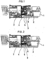
- the anti-theft device contains a bolt 1 which moves with a play in the bolt guide 2 and is fixedly connected to a bolt pull element 5 by translational movement. Depending on the angular position of a cam rotating element 7, the bolt 1 is extended in the locking position (FIG. 1) or withdrawn in the unlocking position (FIG. 2).
- the invention provides for the electrical switch housing 4 of the anti-theft device to be provided with a plastic lamella 3.
- the lamella 3 can be attached or consist of a single piece.
- a bead 6 is formed on the locking element 5, which deforms the lamella 3 of the switch 4 in the end position. The pressure thus caused is transmitted to the bolt 1 via the pulling element 5 and the bolt 1 prevents further collision since it is forced to come into firm contact with the undersides and / or tops of the bolt guide 2.
Landscapes
- Engineering & Computer Science (AREA)
- Mechanical Engineering (AREA)
- Lock And Its Accessories (AREA)
Description
- Die Erfindung betrifft eine Lenkschloß-Diebstahlsicherung mit einem Riegel, der sich in einer Riegelführung bewegt und mit einem Riegelzugelement verbunden ist.
- Bei Einwirkung von Erschütterungen ermöglicht das Spiel, welches für die Gleitbewegung des Riegels in seiner Führung erforderlich ist, ein Aneinanderstoßen dieser beiden Teile, wodurch im Fahrgastraum des Fahrzeuges ein als unzulässig angesehenes Geräusch entsteht.
- Die vorliegende Erfindung hat den Zweck, dieser Schwierigkeit abzuhelfen.
- Zu diesem Zweck ist die Diebstahlsicherung gemäß der Erfindung dadurch gekennzeichnet, daß eine elastische Längslamelle aus Kunststoff mit einem Wulst des Riegelzugelements zusammenwirkt, wenn der Riegel sich in entriegeltem Zustand befindet. Diese Lamelle ist fest mit dem Schaltergehäuse verbunden und besteht vorzugsweise aus einem einzigen Stück.
- Ein besseres Verständnis der Erfindung ergibt sich beim Lesen der nachfolgenden Beschreibung, worin auf die beigefügte Zeichnung Bezug genommen wird, in der:
- - die Figur 1 einen Längsschnitt durch eine Diebstahlsicherung gemäß einem Ausführungsbeispiel der Erfindung mit ausgefahrenem Riegel darstellt; und
- - die Figur 2 der Figur 1 entspricht, wobei jedoch der Riegel zurückgezogen ist.
- Die Diebstahlsicherung enthält einen Riegel 1, der sich mit einem Spiel in der Riegelführung 2 bewegt und durch Translationsbewegung fest mit einem Riegelzugelement 5 verbunden ist. Je nach Winkelstellung eines Nockendrehelements 7 wird der Riegel 1 in Verriegelungsstellung ausgefahren (Figur 1) oder in Entriegelungsstellung zurückgezogen (Figur 2).
- In dieser Entriegelungsstellung, die das Fahren des Fahrzeugs ermöglicht, bewirkt das Aneinanderstoßen des Riegels 1 und der Riegelführung 2 ein unangenehmes Geräusch.
- Um dieses Geräusch zu beseitigen, sieht die Erfindung vor, das elektrische Schaltergehäuse 4 der Diebstahlsicherung mit einer Kunststofflamelle 3 zu versehen. Die Lamelle 3 kann aufgesteckt sein oder aus einem einzigen Stück bestehen. Außerdem ist am Riegelzugelement 5 ein Wulst 6 ausgebildet, der die Lamelle 3 des Schalters 4 in der Endlage verformt. Der so bewirkte Druck wird über das Zugelement 5 auf den Riegel 1 übertragen und der Riegel 1 verhindert das weitere Aneinanderstoßen, da er gezwungen wird, mit den Unterseiten und/oder Oberseiten der Riegelführung 2 in festen Kontakt zu kommen.
Claims (2)
Applications Claiming Priority (2)
| Application Number | Priority Date | Filing Date | Title |
|---|---|---|---|
| FR8701991A FR2610882B1 (fr) | 1987-02-17 | 1987-02-17 | Antivol de direction pour vehicule automobile |
| FR8701991 | 1987-02-17 |
Publications (2)
| Publication Number | Publication Date |
|---|---|
| EP0284723A1 EP0284723A1 (de) | 1988-10-05 |
| EP0284723B1 true EP0284723B1 (de) | 1990-09-12 |
Family
ID=9347993
Family Applications (1)
| Application Number | Title | Priority Date | Filing Date |
|---|---|---|---|
| EP19880101309 Expired - Lifetime EP0284723B1 (de) | 1987-02-17 | 1988-01-29 | Automobil-Lenkschloss |
Country Status (4)
| Country | Link |
|---|---|
| EP (1) | EP0284723B1 (de) |
| DE (1) | DE3860585D1 (de) |
| ES (1) | ES2017767B3 (de) |
| FR (1) | FR2610882B1 (de) |
Families Citing this family (3)
| Publication number | Priority date | Publication date | Assignee | Title |
|---|---|---|---|---|
| FR2716694B1 (fr) * | 1994-02-28 | 1996-04-19 | Valeo Securite Habitacle | Antivol de direction de véhicule automobile comportant des moyens de blocage du pêne de verrouillage. |
| FR2737453B1 (fr) * | 1995-08-01 | 1997-08-29 | Antivols Simplex Sa | Agencement d'un antivol de colonne de direction |
| FR2799426B1 (fr) * | 1999-09-17 | 2001-12-07 | Valeo Securite Habitacle | Antivol de direction de vehicule automobile |
Family Cites Families (4)
| Publication number | Priority date | Publication date | Assignee | Title |
|---|---|---|---|---|
| FR1114810A (fr) * | 1952-07-11 | 1956-04-17 | Antivol de direction combiné | |
| DE1099873B (de) * | 1958-07-03 | 1961-02-16 | Huelsbeck & Fuerst | Sicherungsvorrichtung gegen Diebstahl von Kraftfahrzeugen |
| US3629818A (en) * | 1968-11-12 | 1971-12-21 | Nissan Motor | Antitheft device for a motor vehicle |
| IT206914Z2 (it) * | 1985-08-02 | 1987-10-19 | Magneti Marelli Spa | Dispositivo antifurto bloccasterzo per autoveicoli particolarmente del tipo associato ad un commutatore di accensione |
-
1987
- 1987-02-17 FR FR8701991A patent/FR2610882B1/fr not_active Expired
-
1988
- 1988-01-29 ES ES88101309T patent/ES2017767B3/es not_active Expired - Lifetime
- 1988-01-29 DE DE8888101309T patent/DE3860585D1/de not_active Expired - Lifetime
- 1988-01-29 EP EP19880101309 patent/EP0284723B1/de not_active Expired - Lifetime
Also Published As
| Publication number | Publication date |
|---|---|
| FR2610882A1 (fr) | 1988-08-19 |
| EP0284723A1 (de) | 1988-10-05 |
| ES2017767B3 (es) | 1991-03-01 |
| DE3860585D1 (de) | 1990-10-18 |
| FR2610882B1 (fr) | 1989-05-05 |
Similar Documents
| Publication | Publication Date | Title |
|---|---|---|
| EP1512814B2 (de) | Kraftfahrzeug-Türschliesssystem und Türgriff | |
| DE4230820C2 (de) | Schnappschloß | |
| DE3436318C2 (de) | Schloß, insbesondere für schwenkbare Hauben, Klappen oder dergleichen von Kraftwagen | |
| DE3203702A1 (de) | Betaetigungsvorrichtung fuer ein automatisches kraftfahrzeug-getriebe | |
| DE19548082A1 (de) | Doppelsperrschloß-Betätigungselement | |
| DE3314072A1 (de) | Schlosssystem zur mechanischen und elektronischen steuerung von verriegelungen in einem kraftfahrzeug | |
| DE3425108C1 (de) | Verriegelungsvorrichtung fuer Schloesser der Hintertueren eines Kraftfahrzeuges | |
| EP0475037A1 (de) | Kraftfahrzeug-Türschloss | |
| DE2252356A1 (de) | Sicherheitsgurtanordnung | |
| EP0284723B1 (de) | Automobil-Lenkschloss | |
| EP0231450A1 (de) | Sicherheitslenkschloss bei eingestecktem Schlüssel | |
| EP0320008A2 (de) | Elektromotorisch angetriebenes Türschloss | |
| DE4108507C2 (de) | Kraftfahrzeugtürverschluß mit Zentralverriegelungsantrieb | |
| EP3227147B1 (de) | Verriegelungseinrichtung für ein kraftfahrzeug | |
| DE19727536A1 (de) | Türhandgriff für Kraftfahrzeuge | |
| EP1108835A2 (de) | Türaussengriffanordnung für eine Kraftfahrzeugtür, Kraftfahrzeugtür und Verfahren zur Montage eines Türaussengriffs | |
| DE3242152C2 (de) | ||
| DE19827132A1 (de) | Außengriffanordnung für eine Kraftfahrzeugtür | |
| DE19634627C1 (de) | Lenkradsperre für ein Kraftfahrzeug mit Wegfahrsperre | |
| DE102007042765A1 (de) | Bedienelement mit einem nach einem Kopfaufschlag reversiblen Bedienkopf für ein Fahrzeug | |
| DE3109870C2 (de) | Einrichtung zum Zerstören von Scheiben eines Fahrzeuges | |
| EP0342378A2 (de) | Diebstahlsicherung eines versenkt anzuordnenden Einbaugerätes | |
| DE102018123734A1 (de) | Vorrichtung, System und Verfahren zum Sichern einer Last in einem Fahrzeug | |
| DE2948390A1 (de) | Zentralverriegelungsanlage | |
| DE102007056753B4 (de) | Karteneinzugsvorrichtung |
Legal Events
| Date | Code | Title | Description |
|---|---|---|---|
| PUAI | Public reference made under article 153(3) epc to a published international application that has entered the european phase |
Free format text: ORIGINAL CODE: 0009012 |
|
| 17P | Request for examination filed |
Effective date: 19880803 |
|
| AK | Designated contracting states |
Kind code of ref document: A1 Designated state(s): DE ES FR GB IT |
|
| 17Q | First examination report despatched |
Effective date: 19900117 |
|
| RAP1 | Party data changed (applicant data changed or rights of an application transferred) |
Owner name: VALEO NEIMANN |
|
| RAP3 | Party data changed (applicant data changed or rights of an application transferred) |
Owner name: VALEO NEIMAN |
|
| GRAA | (expected) grant |
Free format text: ORIGINAL CODE: 0009210 |
|
| AK | Designated contracting states |
Kind code of ref document: B1 Designated state(s): DE ES FR GB IT |
|
| GBT | Gb: translation of ep patent filed (gb section 77(6)(a)/1977) | ||
| REF | Corresponds to: |
Ref document number: 3860585 Country of ref document: DE Date of ref document: 19901018 |
|
| ET | Fr: translation filed | ||
| ITF | It: translation for a ep patent filed | ||
| PLBE | No opposition filed within time limit |
Free format text: ORIGINAL CODE: 0009261 |
|
| STAA | Information on the status of an ep patent application or granted ep patent |
Free format text: STATUS: NO OPPOSITION FILED WITHIN TIME LIMIT |
|
| 26N | No opposition filed | ||
| ITTA | It: last paid annual fee | ||
| PGFP | Annual fee paid to national office [announced via postgrant information from national office to epo] |
Ref country code: DE Payment date: 20010116 Year of fee payment: 14 |
|
| PGFP | Annual fee paid to national office [announced via postgrant information from national office to epo] |
Ref country code: GB Payment date: 20010123 Year of fee payment: 14 |
|
| PGFP | Annual fee paid to national office [announced via postgrant information from national office to epo] |
Ref country code: FR Payment date: 20010131 Year of fee payment: 14 |
|
| PGFP | Annual fee paid to national office [announced via postgrant information from national office to epo] |
Ref country code: ES Payment date: 20010223 Year of fee payment: 14 |
|
| REG | Reference to a national code |
Ref country code: GB Ref legal event code: IF02 |
|
| PG25 | Lapsed in a contracting state [announced via postgrant information from national office to epo] |
Ref country code: GB Free format text: LAPSE BECAUSE OF NON-PAYMENT OF DUE FEES Effective date: 20020129 |
|
| PG25 | Lapsed in a contracting state [announced via postgrant information from national office to epo] |
Ref country code: ES Free format text: LAPSE BECAUSE OF NON-PAYMENT OF DUE FEES Effective date: 20020130 |
|
| PG25 | Lapsed in a contracting state [announced via postgrant information from national office to epo] |
Ref country code: DE Free format text: LAPSE BECAUSE OF NON-PAYMENT OF DUE FEES Effective date: 20020801 |
|
| GBPC | Gb: european patent ceased through non-payment of renewal fee |
Effective date: 20020129 |
|
| PG25 | Lapsed in a contracting state [announced via postgrant information from national office to epo] |
Ref country code: FR Free format text: LAPSE BECAUSE OF NON-PAYMENT OF DUE FEES Effective date: 20020930 |
|
| REG | Reference to a national code |
Ref country code: FR Ref legal event code: ST |
|
| REG | Reference to a national code |
Ref country code: ES Ref legal event code: FD2A Effective date: 20030922 |
|
| PG25 | Lapsed in a contracting state [announced via postgrant information from national office to epo] |
Ref country code: IT Free format text: LAPSE BECAUSE OF NON-PAYMENT OF DUE FEES;WARNING: LAPSES OF ITALIAN PATENTS WITH EFFECTIVE DATE BEFORE 2007 MAY HAVE OCCURRED AT ANY TIME BEFORE 2007. THE CORRECT EFFECTIVE DATE MAY BE DIFFERENT FROM THE ONE RECORDED. Effective date: 20050129 |