EP0284743A2 - Fixation de sécurité pour le ski - Google Patents
Fixation de sécurité pour le ski Download PDFInfo
- Publication number
- EP0284743A2 EP0284743A2 EP88101909A EP88101909A EP0284743A2 EP 0284743 A2 EP0284743 A2 EP 0284743A2 EP 88101909 A EP88101909 A EP 88101909A EP 88101909 A EP88101909 A EP 88101909A EP 0284743 A2 EP0284743 A2 EP 0284743A2
- Authority
- EP
- European Patent Office
- Prior art keywords
- locking element
- spring
- bearing block
- locking
- safety ski
- Prior art date
- Legal status (The legal status is an assumption and is not a legal conclusion. Google has not performed a legal analysis and makes no representation as to the accuracy of the status listed.)
- Granted
Links
Images



Classifications
-
- A—HUMAN NECESSITIES
- A63—SPORTS; GAMES; AMUSEMENTS
- A63C—SKATES; SKIS; ROLLER SKATES; DESIGN OR LAYOUT OF COURTS, RINKS OR THE LIKE
- A63C9/00—Ski bindings
- A63C9/08—Ski bindings yieldable or self-releasing in the event of an accident, i.e. safety bindings
- A63C9/084—Ski bindings yieldable or self-releasing in the event of an accident, i.e. safety bindings with heel hold-downs, e.g. swingable
- A63C9/0846—Details of the release or step-in mechanism
-
- A—HUMAN NECESSITIES
- A63—SPORTS; GAMES; AMUSEMENTS
- A63C—SKATES; SKIS; ROLLER SKATES; DESIGN OR LAYOUT OF COURTS, RINKS OR THE LIKE
- A63C9/00—Ski bindings
- A63C9/08—Ski bindings yieldable or self-releasing in the event of an accident, i.e. safety bindings
- A63C9/084—Ski bindings yieldable or self-releasing in the event of an accident, i.e. safety bindings with heel hold-downs, e.g. swingable
- A63C9/0841—Ski bindings yieldable or self-releasing in the event of an accident, i.e. safety bindings with heel hold-downs, e.g. swingable with a single jaw
- A63C9/0842—Ski bindings yieldable or self-releasing in the event of an accident, i.e. safety bindings with heel hold-downs, e.g. swingable with a single jaw the jaw pivoting on the body or base about a transverse axis
-
- A—HUMAN NECESSITIES
- A63—SPORTS; GAMES; AMUSEMENTS
- A63C—SKATES; SKIS; ROLLER SKATES; DESIGN OR LAYOUT OF COURTS, RINKS OR THE LIKE
- A63C9/00—Ski bindings
- A63C9/08—Ski bindings yieldable or self-releasing in the event of an accident, i.e. safety bindings
- A63C9/084—Ski bindings yieldable or self-releasing in the event of an accident, i.e. safety bindings with heel hold-downs, e.g. swingable
- A63C9/0845—Ski bindings yieldable or self-releasing in the event of an accident, i.e. safety bindings with heel hold-downs, e.g. swingable the body or base or a jaw pivoting about a vertical axis, i.e. side release
-
- A—HUMAN NECESSITIES
- A63—SPORTS; GAMES; AMUSEMENTS
- A63C—SKATES; SKIS; ROLLER SKATES; DESIGN OR LAYOUT OF COURTS, RINKS OR THE LIKE
- A63C9/00—Ski bindings
- A63C9/005—Ski bindings with means for adjusting the position of a shoe holder or of the complete binding relative to the ski
-
- A—HUMAN NECESSITIES
- A63—SPORTS; GAMES; AMUSEMENTS
- A63C—SKATES; SKIS; ROLLER SKATES; DESIGN OR LAYOUT OF COURTS, RINKS OR THE LIKE
- A63C9/00—Ski bindings
- A63C9/08—Ski bindings yieldable or self-releasing in the event of an accident, i.e. safety bindings
- A63C9/084—Ski bindings yieldable or self-releasing in the event of an accident, i.e. safety bindings with heel hold-downs, e.g. swingable
- A63C9/0847—Details of the manual release
Definitions
- the invention relates to a safety ski binding with a bearing block that can be swiveled out laterally about a vertical axis against the force of a return spring and relative to a base plate that can be displaced parallel to the upper side of the ski, with a latching rocker that is loaded by a release spring and cooperates with a bearing block that is fixed to the bearing block and that is mounted against pivoting of a bearing block on the bearing block Sole holder acts in the vertical direction, with a preferably base plate-fixed control track and a locking element associated with this control track, preferably formed on the sole holder, for controlling the lateral triggering between the base plate and sole holder, and with a pivoting out of the bearing block in a position locked in a counter-locking position when the binding is open the base plate inhibiting locking element, the locking rocker or a component rigidly connected to it a control zone actuating the locking element against the load of a spring device points.
- a locking element is provided, which on the one hand should prevent the pivoting of the bearing block about a vertical axis when closing the binding and on the other hand should not hinder the diagonal release process "(vertical and lateral pivoting out of the SOHA or bearing block when the binding is released) .
- the control zone moved with the locking rocker allows a more precise control of the locking element than is possible by means of binding housing parts and also offers the possibility of arranging the locking element in the interior of the binding, protected from icing.
- the more space-saving, simpler design variants place high demands on manufacturing accuracy and the materials used, since the position in which the locking rocker engages under the locking lug must coincide exactly with the position in which the locking element emerges from the counter-locking or enters it.
- This goal can be achieved completely, namely when getting into the binding, to keep it centered for a long time, and on the other hand not to hinder a diagonal release process at all, at best by a complex variant of the known binding, in which a guide part of the locking element when opening and closing the Binding slides in different control grooves.
- this variant is complex and takes up a lot of space.
- the object of the invention is to provide a compact and functionally reliable safety ski binding of the type mentioned at the outset, even in the case of coarser manufacturing tolerances and in which the locking element swings out the bearing block, and thus the sole holder, from the centered central position, even in difficult terrain, when boarding in the event of constant side loading, is prevented without, however, preventing the bearing block from swiveling out to the side during the triggering process.
- the locking element has at least one spring element, by means of which the locking element can be actuated by bearing the control zone on the spring element against the load caused by the spring device, and in that the counter-locking means for the locking element have lateral contact surfaces, one of which each Locking element when closing the binding with a laterally loaded sole holder or bearing block until it reaches a certain compression or elongation of the spring element caused by the control zone in a locked position.
- the locking element Through the indirect actuation of the locking element via a spring element, it is achieved in a simple manner that the locking element is actuated by the control zone of the locking rocker, but that the position of the control zone or the locking rocker does not exclusively determine the position of the locking element.
- the locking element can therefore "get caught” for a long time on a lateral contact surface of the counter-latch and thus prevent the sole holder from swinging out sideways when it gets in.
- the spring element is compressed (compression spring arrangement) or elongated (tension spring arrangement), the closing movement of the locking rocker not being hindered by the locking element remaining behind.
- a guide rail 2 is fastened on a ski 1 by means of only indicated screws.
- a heel holder of a safety ski binding designated in its entirety by 3
- the base plate 4 can be locked together with the heel holder arranged on it in a known and therefore not shown manner for adapting the binding to differently long ski boots in the desired position.
- a vertical axis 5 designed as a pivot is riveted, around which a bearing block 6 of the heel holder 3 fastened on a pivot plate 6a is pivotably mounted in the horizontal plane against the force of a return spring 7.
- the thigh Spring-formed return spring 7 is formed to form a loop around the pivot pin 5. Its two free legs 7a point towards the rear end of the binding and are each provided with a bent end region 7b towards the top of the ski. By means of these bent end regions 7b, the return spring 7 is supported on a recess 6b formed on the rear end region of the swivel plate 6a and / or on a recess 4a formed on the rear end region of the base plate 4.
- a sole holder 8 is pivotally mounted about an axis 9 running transversely to the longitudinal axis of the ski.
- the sole holder 8 is held in its position holding the shoe by means of a latching device (latching rocker 16, latching nose 17) which is spring-loaded by a release spring 14.
- the locking rocker 16 is pivotally mounted on the sole holder 8 on an axis 30.
- an approximately U-shaped spring housing 12 located within the side walls of the bearing block 6 is pivotably mounted.
- the spring housing 12 receives at least one release spring 14, which acts on one end of a locking part 15, which engages in the locking pan of the pivoting arm 16 pivotally mounted on the sole holder 8, which in turn engages under the bearing block-fixed locking lug 17 in the downward position with a locking projection 16a.
- the second end of the release spring 14 is supported on a spring abutment 18 which is adjustable in the axial direction of the release spring 14 by means of a screw 19 rotatably mounted in the spring housing.
- the cover 20 thus pivots together with the spring housing 12.
- the cover 20 is equipped with a window provided with a scale, which is provided for displaying the set spring preload.
- FIG. 1 The locking effective against pivoting in the horizontal plane is shown in FIG.
- a notch 8a formed on the sole holder 8 lies in the downward position of the heel holder 3 in a detent recess 13b of a control cam 13a which is formed on a detent part 13 which is firmly connected to the base plate 4 via a fastening part 13c.
- the front end region of the swivel plate 6a carrying the bearing block 6 engages under the fastening part 13c of the latching part 13 and is rounded concentrically to the vertical axis 5. In this way, on the one hand, an unobstructed pivoting movement of the bearing block 6 is ensured and, on the other hand, the bearing block 6 is additionally secured against lifting off from the guide plate 4.
- the heel holder 3 is locked against a purely lateral release by the latching recess 13b of the control cam 13a.
- the front jaw, not shown, is therefore responsible for a purely lateral triggering process. If composite, so-called diagonal forces occur, after overcoming the blocking zone, the control cam 13a of the latching part 13 comes into play, which allows the pivoted-up sole holder 8 to pivot laterally.
- a release lever 20a is provided which, like the locking rocker 16, is pivotably mounted on the sole holder 8 about the axis 30. If the heel holder 3 shown in the downward position in FIG. 1 is to be opened, the release lever 20a together with its driving axis 21 is pivoted up. Through the upward moving driver Axis 21 pivots the spring housing 12 in a clockwise direction and the locking rocker 16 in a counterclockwise direction, so that the locking projection 16a no longer engages under the locking lug 17 and thus the sole holder 8 together with the locking rocker 17 can pivot upward into a position releasing a shoe, not shown.
- the locking element to prevent lateral pivoting of the sole holder 8 or the bearing block 6 about the vertical axis 5 when entering difficult terrain consists of the horizontally lying spring tongue 40 connected to the bearing block 6, which is in the in 1 is in a disengaged position from the base plate-fixed counter detent 41, being held down by the control zone 42 of the nose 16b pointing towards the base plate 4 on the detent rocker 16 engaging under the detent 17 against its own spring action.
- lateral pivoting of the pedestal 6 about the vertical axis 5 should be possible at least in the initial phase of a diagonal triggering process, in which the catch 8a of the sole holder slides along the control plate 13 fixed to the base plate (FIG. 2) by the locking element (spring tongue 40) as far as possible long bassed out.
- the spring tongue 40 should remain in the locked position (in which a lateral pivoting out of the sole holder 8 is not possible) until the catch 8a is between the control cams 13a shown in FIG.
- FIGS. 3 to 11 An embodiment of such a binding according to the invention is shown schematically in FIGS. 3 to 11 in different binding positions, essentially only the parts essential for the function of the locking element being shown. The same or analogous parts are identified in the same way as in FIGS. 1 and 2.
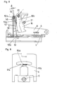
- the locking element consists of a component 50 which is pivotably mounted about an axis 52 on the bearing block 6 and, depending on the position, with its extension 50a lies between the contact surfaces 51a and 51b of the counter-latch 51 fixed to the base plate (latched position, FIGS. 6 to 9) or not (disengaged) Location, Fig. 3 to 5 and 10, 11).
- a locking element takes up little space in the binding housing.
- the locking element is pivoted by control zones 42, which are formed on a lever 16b which is fixedly connected to the locking rocker 16, via two spring elements 53a, 53b which are symmetrical to the longitudinal axis of the binding, counter to a torque acting counterclockwise, which from the spring device 54a, 54b acts on the Locking element 50 is exercised.
- the spring elements each consist of a leg spring which is coaxial with the pivot axis 52 of the locking element 50, one leg of which is essentially formed by the locking element 50 and the actual leg 53a of which stands out from the locking element 50 at an angle in the unloaded state (FIG. 6, binding ready for entry) .
- the coil spring part 53b of this leg spring is in each case fixedly pressed or otherwise connected to the locking element 50 at the points 55 (FIG. 4).
- the control zones 42 each abut the legs 53a. In this way, simple and functionally reliable pressure spring elements which can be pressed against the locking element 50 are formed and take up little space.
- the spring device which applies a torque to the locked position towards the locking element 50, is formed in one piece with the spring element (s) 53a, 53b of the locking element 50.
- the spring element (s) 53a, 53b of the locking element 50 As can be seen from FIG. 4, two helical springs coaxial with the pivot axis 52 are provided for this purpose, each of which is firmly connected to the locking element 50 in a central region (at the points 55), the one helical spring parts 53b belonging to the spring element each being in continue the actual leg 53a of the spring elements and the other coil spring parts 54a continue into further legs 54b which are supported on a bracket 56 fixed to the bearing block (and thus produce the torque counterclockwise on the locking element 50) and merge into one another.
- the two spring elements and the spring device are thus advantageously formed in one piece.
- the binding is in the down position (closed position).
- the locking element 50 (or its extension 50a) is disengaged from the counter detent 51 (FIG. 5) and does not inhibit a lateral pivoting of the bearing block 6 about the vertical axis 5.
- a stop fixed to the bearing block limits the pivoting path of the locking element 50, which is vertical in the closed position of the binding.
- the legs 53a of the spring element are pressed as far as the blocking element 50 and the control zones 42 bear directly against the latter in the lower region. The locking element 50 and the spring elements thus advantageously take up little space in the closed position of the binding.
- the binding ready for boarding is shown in FIGS. 6 and 7.
- the locking element is pivoted counterclockwise into the counter detent 51 under the action of the spring device 54a, 54b.
- the control zones 42 are pivoted upward with the locking rocker 16 or the levers 16b attached thereto, so that the spring elements are almost relaxed (the legs 53a are lifted off the locking element 50).
- the bearing block 6 tries to pivot out laterally about the vertical axis 5 relative to the base plate 4.
- the task of the locking element 50 is to prevent this by making it possible for a long time (ie until the locking rocker 16 engages under the locking lug 17 and a catch formed on the sole holder has penetrated into a locking recess which reliably prevents the sole holder and the bearing block from pivoting out to the side). remains locked in the counter detent 51.
- the contact surfaces 51a and 51b of the counter-catch are slightly undercut (FIG. 9), as a result of which the extension 50a of the locking element 50, which bears against one of these contact surfaces 51b when the binding is loaded laterally, is initially retained in the locked position when the binding is closed.
- This lagging behind the control zones 42 of the locking rocker arm 16 closing is only possible by the spring elements, whereby these are compressed.
- the locking rocker 16 already engages under the locking lug.
- the locking element 50 is still locked and the legs 53a of the spring elements are compressed up to an angle ⁇ to the locking element 50.
- the extension 50a overcomes the projection formed by the contact surface 51b and the locking element disengages.
- the binding is then already securely locked.
- the undercuts of the contact surfaces 51a and 51b are advantageous, but not absolutely necessary.
- the friction between the extension 50a and the contact surface can be sufficient to retain the locking element 50 when the closure is loaded laterally.
- the locking element 50 with the lateral contact surfaces 51a, 51b of the counter detent 51 cooperating surfaces which enclose an acute angle with the direction of movement of the locking element 50 which is essentially present when the locking element is disengaged, and which are in contact with one of the contact surfaces 51a, 51b the counter detent 51 each extend parallel to this contact surface 51a or 51b, point loads are avoided.
- FIG. 10 and 11 show the binding in the event of a forward fall or in the first phase of a diagonal release.
- the locking rocker 16 is in the same as in FIG. 8, the locking element 50 in FIG. 10 is disengaged (cf. also FIG. 11) and hinders a lateral disengagement of the bearing block 6 and thus also a diagonal release process which only takes place when one is in Fig. 10 uses the position shown, in no way. If a diagonal triggering process begins, the extension 50a comes in front of the surfaces 57a and 57b lying on the side of the counter-latch, with the locking element 50 being held out until the heel holder is centered again and the locking element 50 snaps into the counter-latch under the action of the spring device.
- the spring device 54a, 54b and the spring elements 53a, 53b compete, which load the locking element 50 in different directions. Since the torque caused by the spring elements 53a, 53b is greater in the area of the closed position than the opposite torque caused by the spring device 54a, 54b, the locking element 50 advantageously initially stops when opening and only follows when the spring elements (angle ⁇ , Fig 10) the control zone 42 or the legs 53a.
- the invention is not restricted to the exemplary embodiments shown. Both the location and the design of the locking element can vary.
- the spring element can be designed as a leaf spring riveted onto the locking element.
- An even simpler construction is one in which the spring element is formed in one piece with the locking element made of resilient material.
- the locking element need only have a spring element, and tension spring arrangements are also conceivable in principle.
- the spring device that continuously acts on the locking element can also be integrated in the locking element, i.e. the locking element can be resilient in itself.
- the spring device it is also possible, for example, for the spring device to consist of a leaf spring riveted onto the locking element.
Landscapes
- Footwear And Its Accessory, Manufacturing Method And Apparatuses (AREA)
- Fittings On The Vehicle Exterior For Carrying Loads, And Devices For Holding Or Mounting Articles (AREA)
Applications Claiming Priority (2)
| Application Number | Priority Date | Filing Date | Title |
|---|---|---|---|
| AT0077487A AT386749B (de) | 1987-03-31 | 1987-03-31 | Sicherheitsskibindung |
| AT774/87 | 1987-03-31 |
Publications (3)
| Publication Number | Publication Date |
|---|---|
| EP0284743A2 true EP0284743A2 (fr) | 1988-10-05 |
| EP0284743A3 EP0284743A3 (fr) | 1991-05-15 |
| EP0284743B1 EP0284743B1 (fr) | 1993-08-04 |
Family
ID=3499401
Family Applications (1)
| Application Number | Title | Priority Date | Filing Date |
|---|---|---|---|
| EP88101909A Expired - Lifetime EP0284743B1 (fr) | 1987-03-31 | 1988-02-10 | Fixation de sécurité pour le ski |
Country Status (3)
| Country | Link |
|---|---|
| EP (1) | EP0284743B1 (fr) |
| AT (1) | AT386749B (fr) |
| DE (1) | DE3882764D1 (fr) |
Families Citing this family (1)
| Publication number | Priority date | Publication date | Assignee | Title |
|---|---|---|---|---|
| AT396064B (de) * | 1989-07-13 | 1993-05-25 | Tyrolia Freizeitgeraete | Fersenhalter |
Family Cites Families (4)
| Publication number | Priority date | Publication date | Assignee | Title |
|---|---|---|---|---|
| AT370334B (de) * | 1981-03-04 | 1983-03-25 | Tyrolia Freizeitgeraete | Sicherheitsskibindung |
| AT376374B (de) * | 1983-02-01 | 1984-11-12 | Tyrolia Freizeitgeraete | Sicherheitsskibindung |
| AT377190B (de) * | 1983-05-06 | 1985-02-25 | Tyrolia Freizeitgeraete | Sicherheitsskibindung |
| AT383498B (de) * | 1985-08-19 | 1987-07-10 | Tyrolia Freizeitgeraete | Sicherheitsskibindung |
-
1987
- 1987-03-31 AT AT0077487A patent/AT386749B/de not_active IP Right Cessation
-
1988
- 1988-02-10 EP EP88101909A patent/EP0284743B1/fr not_active Expired - Lifetime
- 1988-02-10 DE DE8888101909T patent/DE3882764D1/de not_active Expired - Fee Related
Also Published As
| Publication number | Publication date |
|---|---|
| EP0284743A3 (fr) | 1991-05-15 |
| EP0284743B1 (fr) | 1993-08-04 |
| DE3882764D1 (de) | 1993-09-09 |
| AT386749B (de) | 1988-10-10 |
| ATA77487A (de) | 1988-03-15 |
Similar Documents
| Publication | Publication Date | Title |
|---|---|---|
| DE3310961A1 (de) | Vorrichtung zur arretierung einer voll geoeffneten schiebetuer eines fahrzeugs | |
| AT401710B (de) | Skischuh | |
| EP0156379A2 (fr) | Tiroir-caisse pour une caisse enregistreuse | |
| AT397603B (de) | Spannschnalle | |
| DE3515847A1 (de) | Seitenbacken-verriegelung | |
| DE69401171T2 (de) | Bindungselement für einen alpinen Ski | |
| DE3137552A1 (de) | "schnaepperscharnier" | |
| DE8805834U1 (de) | Feststellvorrichtung für eine mit einem Türschließer versehene Tür | |
| EP0216123B1 (fr) | Fixation de sécurité pour skis | |
| EP0284743B1 (fr) | Fixation de sécurité pour le ski | |
| CH653560A5 (de) | Mit einer skibremse kombinierter fersenhalter. | |
| DE4424737C1 (de) | Snowboardbindung | |
| EP0700311B1 (fr) | Dispositif de fixation de ski servant a fixer une chaussure de ski sur un ski, notamment un ski de randonnee ou ski de fond | |
| DE2707838A1 (de) | Sicherheitsskibindung mit an einem grundkoerper schwenkbar angeordnetem sohlenhalter und einer eingebauten skibremse | |
| EP1001126B1 (fr) | Dispositif de fixage | |
| EP0208206B1 (fr) | Fixation de sécurité de ski, en particulier talonnière | |
| DE2211070C3 (de) | Niederhalter für eine Skibindung | |
| EP0495192A1 (fr) | Fixation de ski pour ski de fond | |
| DE2552729C2 (de) | Kreuzgelenk-Schnäpperscharnier | |
| DE3240183A1 (de) | Backen einer sicherheitsskibindung | |
| EP0671521B1 (fr) | Verrou de position de nettoyage | |
| EP0072904B1 (fr) | Talonnière pour fixation de ski | |
| AT384952B (de) | Sicherheitsskibindung | |
| EP0470419B1 (fr) | Fixation arrière de sécurité | |
| CH665131A5 (de) | Fersenhalter. |
Legal Events
| Date | Code | Title | Description |
|---|---|---|---|
| PUAI | Public reference made under article 153(3) epc to a published international application that has entered the european phase |
Free format text: ORIGINAL CODE: 0009012 |
|
| AK | Designated contracting states |
Kind code of ref document: A2 Designated state(s): CH DE FR LI |
|
| PUAL | Search report despatched |
Free format text: ORIGINAL CODE: 0009013 |
|
| AK | Designated contracting states |
Kind code of ref document: A3 Designated state(s): CH DE FR LI |
|
| RAP1 | Party data changed (applicant data changed or rights of an application transferred) |
Owner name: TMC CORPORATION |
|
| 17P | Request for examination filed |
Effective date: 19911024 |
|
| RAP1 | Party data changed (applicant data changed or rights of an application transferred) |
Owner name: HTM SPORT- UND FREIZEITGERAETE GESELLSCHAFT M.B.H. |
|
| 17Q | First examination report despatched |
Effective date: 19921218 |
|
| GRAA | (expected) grant |
Free format text: ORIGINAL CODE: 0009210 |
|
| AK | Designated contracting states |
Kind code of ref document: B1 Designated state(s): CH DE FR LI |
|
| REF | Corresponds to: |
Ref document number: 3882764 Country of ref document: DE Date of ref document: 19930909 |
|
| ET | Fr: translation filed | ||
| RAP2 | Party data changed (patent owner data changed or rights of a patent transferred) |
Owner name: HTM SPORT- UND FREIZEITGERAETE AKTIENGESELLSCHAFT |
|
| REG | Reference to a national code |
Ref country code: CH Ref legal event code: PFA Free format text: HTM SPORT- UND FREIZEITGERAETE AKTIENGESELLSCHAFT |
|
| PG25 | Lapsed in a contracting state [announced via postgrant information from national office to epo] |
Ref country code: LI Effective date: 19940228 Ref country code: CH Effective date: 19940228 |
|
| PLBE | No opposition filed within time limit |
Free format text: ORIGINAL CODE: 0009261 |
|
| STAA | Information on the status of an ep patent application or granted ep patent |
Free format text: STATUS: NO OPPOSITION FILED WITHIN TIME LIMIT |
|
| 26N | No opposition filed | ||
| PG25 | Lapsed in a contracting state [announced via postgrant information from national office to epo] |
Ref country code: FR Effective date: 19941031 |
|
| REG | Reference to a national code |
Ref country code: CH Ref legal event code: PL |
|
| REG | Reference to a national code |
Ref country code: FR Ref legal event code: ST |
|
| PGFP | Annual fee paid to national office [announced via postgrant information from national office to epo] |
Ref country code: DE Payment date: 20020207 Year of fee payment: 15 |
|
| PG25 | Lapsed in a contracting state [announced via postgrant information from national office to epo] |
Ref country code: DE Free format text: LAPSE BECAUSE OF NON-PAYMENT OF DUE FEES Effective date: 20030902 |