EP0284773B1 - Dispositif d'élargissement de fins de tubes - Google Patents
Dispositif d'élargissement de fins de tubes Download PDFInfo
- Publication number
- EP0284773B1 EP0284773B1 EP88102680A EP88102680A EP0284773B1 EP 0284773 B1 EP0284773 B1 EP 0284773B1 EP 88102680 A EP88102680 A EP 88102680A EP 88102680 A EP88102680 A EP 88102680A EP 0284773 B1 EP0284773 B1 EP 0284773B1
- Authority
- EP
- European Patent Office
- Prior art keywords
- tube
- mould
- cylinder
- expansion
- die
- Prior art date
- Legal status (The legal status is an assumption and is not a legal conclusion. Google has not performed a legal analysis and makes no representation as to the accuracy of the status listed.)
- Expired - Lifetime
Links
- 238000003780 insertion Methods 0.000 claims description 2
- 230000037431 insertion Effects 0.000 claims description 2
- 238000000034 method Methods 0.000 claims description 2
- 239000004519 grease Substances 0.000 description 1
Images

Classifications
-
- B—PERFORMING OPERATIONS; TRANSPORTING
- B21—MECHANICAL METAL-WORKING WITHOUT ESSENTIALLY REMOVING MATERIAL; PUNCHING METAL
- B21D—WORKING OR PROCESSING OF SHEET METAL OR METAL TUBES, RODS OR PROFILES WITHOUT ESSENTIALLY REMOVING MATERIAL; PUNCHING METAL
- B21D39/00—Application of procedures in order to connect objects or parts, e.g. coating with sheet metal otherwise than by plating; Tube expanders
- B21D39/08—Tube expanders
- B21D39/20—Tube expanders with mandrels, e.g. expandable
-
- B—PERFORMING OPERATIONS; TRANSPORTING
- B21—MECHANICAL METAL-WORKING WITHOUT ESSENTIALLY REMOVING MATERIAL; PUNCHING METAL
- B21D—WORKING OR PROCESSING OF SHEET METAL OR METAL TUBES, RODS OR PROFILES WITHOUT ESSENTIALLY REMOVING MATERIAL; PUNCHING METAL
- B21D41/00—Application of procedures in order to alter the diameter of tube ends
- B21D41/02—Enlarging
Definitions
- the innovation relates to a device for expanding pipe ends according to the preamble of claim 1.
- a device for expanding pipe ends according to the preamble of claim 1.
- Such a device has already become known from US-A-2394841.
- DE-A-1 918 815 describes a device in which a wedge-shaped punch is arranged at the end of a piston. With the cylinder of the piston a holder is connected, which consists of wedge pieces, which lie against the outer wall of the pipe at a distance from the pipe end.
- a disadvantage of this known device is that when the punch is pressed into the pipe end, the pipe is axially displaced at least until the wedges of the holder engage. If the friction between the outer tube wall and the wedge pieces is relatively low, for example if the outer tube wall has a layer of grease, then the tube is displaced over the entire stroke of the piston, so that the plunger is not pressed into the end of the tube.
- the device according to US-A 23 94 841 has a first air cylinder which drives a first rack which is in engagement with a first gear which in turn drives a first eccentric drive which is connected to first connecting rods.
- These first connecting rods hold a clamping block surrounding a die, which, when the first cylinder is actuated, clamps the die, which consists of segments, against the pipe to be expanded.
- a spring is released, which expands an expansion sleeve inside the tube.
- a second air cylinder is actuated, a punch is moved into the interior of the tube via a second toothed rack, a second toothed wheel, another eccentric drive and a further connecting rod.
- the object is to improve the device in such a way that the tube has a secure hold during expansion and the expansion is carried out in a controlled manner.
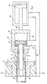
- the pipe end 8 to be expanded is surrounded by a die 1, which is divided into two in the longitudinal direction and has a recess 10 in the region of the end 9 of the pipe.
- the two-part die 1 is arranged in a die holder 11 which is connected to a frame 12.
- the recess 10 determines the outer shape of the widening to be provided at the end 9.
- the frame carries a cylinder 13, which in turn is connected to an expansion sleeve 4.
- This expansion sleeve 4 is inserted with its head 14 into the tube 8 such that its expansion head 14 comes to rest against the inner wall of the tube 8.
- the expansion head 14 is located in the area of the die 1 at the level of the area of the die 1, which adjoins the recess 10.
- expansion mandrel 3 which is conical in the area of the expansion head 14.
- This expanding mandrel 3 is connected to the piston 15 inside the cylinder 13. If a pressure medium is applied to the left cylinder chamber of the cylinder 13, the expanding mandrel 3 executes a movement to the right, in which the conical wedge of the expanding mandrel 3 spreads the expanding head 14 , which is provided with axially extending slots 16 for this purpose.
- This expansion head 14 thus comes to rest against the inner wall of the tube 8, which is held in this way between the die 1 and the expansion head 14.
- the plunger 5 which has an axial bore for this purpose, is slidably arranged on the area of reduced diameter of the expanding sleeve 4 adjoining the expanding head 14.
- This stamp 5 is fastened to a guide housing 17, in which the cylinder 13 is slidably arranged.
- the guide housing 17 has a slot 18 through which the arm 19 of the frame 12 is guided, to which the cylinder 13 is attached.
- the right cylinder chamber of the cylinder 22 is pressurized with a pressure medium, whereby the piston rod 20 moves the plunger 5 in the direction of the tube end 9 via the guide housing 17.
- the punch 5 is pressed into the pipe end 9 in this way, this being deformed against the surface of the recess 10.
- the punch 5 has a cylindrical extension 7, the diameter of which is smaller than the inside diameter of the pipe.
- the die 1, the expansion sleeve 4 and the punch 5 are interchangeable, so that the device can be adapted to different pipe diameters and pipe wall thicknesses.
Landscapes
- Engineering & Computer Science (AREA)
- Mechanical Engineering (AREA)
- Shaping Of Tube Ends By Bending Or Straightening (AREA)
- Mounting, Exchange, And Manufacturing Of Dies (AREA)
- Chair Legs, Seat Parts, And Backrests (AREA)
- Forging (AREA)
- Shaping Metal By Deep-Drawing, Or The Like (AREA)
Claims (5)
- Appareil pour élargir des extrémités de tubes (9) au moyen d'un poinçon (5) pouvant être pressé dans le tube (8) et possédant à peu près une forme en coin, l'appareil comprenant une matrice (1) qui entoure l'extrémité (9) du tube et possède un évidement (10) dans la région de l'élargissement à former, évidement dans lequel peut être engagé le poinçon (5), de même qu'une douille expansible (4, 14), le tube (8) étant maintenu par la douille expansible (4, 14) pendant l'opération d'élargissement, la douille, par son expansion, pouvant être appliquée contre la paroi interne du tube, dans la partie du tube faisant suite à la portion de tube située dans la région de l'évidement (10) de la matrice, de sorte que le tube (8) peut être serré entre la douille expansible (4, 14) et la matrice (1), le poinçon (5), présentant un alésage de guidage, étant disposé coulissant et guidé sur la tige de la douille expansible (4, 14), et un mandrin d'expansion (3) étant disposé coulissant à l'intérieur de la douille expansible, caractérisé en ce que le mandrin d'expansion (3) est relié, par son extrémité éloignée de la tête expansible (14), à un piston (15) d'un vérin (13) dont le cylindre stationnaire est relié à la douille expansible (4, 14), le cylindre de ce vérin (13) est entouré par un carter de guidage (17) portant à une extrémité le poinçon (5), et un vérin stationnaire supplémentaire (22) est prévu pour agir par son piston (21) sur l'autre extrémité du carter de guidage (17).
- Appareil selon la revendication 1, caractérisé en ce que la matrice (1) et le vérin (13) relié à la douille expasible (4, 14), sont portés par un bâti (12) commun.
- Appareil selon la revendication 2, caractérisé en ce que la partie (19) du bâti (12) portant le vérin (13), traverse une lumière (18) ménagée dans le carter de guidage (17).
- Appareil selon la revendication 2 ou 3, caractérisé en ce que le bâti (12) porte le vérin supplémentaire (22).
- Appareil selon une des revendications 1 à 4, caractérisé en ce que la matrice (1) est divisée en deux parties et est maintenue par un porte-matrice (11) qui est lui-même relié au bâti (12).
Applications Claiming Priority (2)
| Application Number | Priority Date | Filing Date | Title |
|---|---|---|---|
| DE8702934U DE8702934U1 (de) | 1987-02-26 | 1987-02-26 | Vorrichtung zum Aufweiten von Rohrenden |
| DE8702934U | 1987-02-26 |
Publications (3)
| Publication Number | Publication Date |
|---|---|
| EP0284773A2 EP0284773A2 (fr) | 1988-10-05 |
| EP0284773A3 EP0284773A3 (en) | 1990-02-28 |
| EP0284773B1 true EP0284773B1 (fr) | 1991-10-02 |
Family
ID=6805210
Family Applications (1)
| Application Number | Title | Priority Date | Filing Date |
|---|---|---|---|
| EP88102680A Expired - Lifetime EP0284773B1 (fr) | 1987-02-26 | 1988-02-24 | Dispositif d'élargissement de fins de tubes |
Country Status (3)
| Country | Link |
|---|---|
| EP (1) | EP0284773B1 (fr) |
| DE (2) | DE8702934U1 (fr) |
| ES (1) | ES2025714T3 (fr) |
Families Citing this family (13)
| Publication number | Priority date | Publication date | Assignee | Title |
|---|---|---|---|---|
| US4934038A (en) * | 1989-09-15 | 1990-06-19 | Caterpillar Inc. | Method and apparatus for tube expansion |
| DE19704131C2 (de) * | 1997-02-04 | 2003-01-02 | Ex Cell O Gmbh | Verfahren und Vorrichtung zum Bruchtrennen |
| HUP9800170A1 (hu) * | 1998-01-30 | 2000-09-28 | Zoltán Farkas | Eljárás kétkerekű járművek, különösen kerékpárok kerékagy hüvelyének előállítására |
| DE10135515B4 (de) | 2001-07-20 | 2006-06-01 | ITT Manufacturing Enterprises, Inc., Wilmington | Umformwerkzeug |
| DE102005059388A1 (de) * | 2005-12-09 | 2007-06-14 | Rennsteig Werkzeuge Gmbh | Vorrichtung zum Aufweiten von Rohrenden |
| GB0608775D0 (en) * | 2006-05-04 | 2006-06-14 | Caldervale Technology Ltd | Device for preparing pipe ends for jointing |
| DE102014008550A1 (de) * | 2014-06-16 | 2015-12-17 | Sms Meer Gmbh | Mechanischer Rohrexpander |
| RU2633676C1 (ru) * | 2016-09-26 | 2017-10-16 | Публичное акционерное общество "Уфимское моторостроительное производственное объединение" | Устройство для вальцевания полых деталей |
| GB2561832A (en) | 2017-04-21 | 2018-10-31 | Eaton Intelligent Power Ltd | Arrangement for working a tube end |
| US10940521B2 (en) | 2017-06-29 | 2021-03-09 | Milwaukee Electric Tool Corporation | Swage tool |
| CN110479826A (zh) * | 2019-07-26 | 2019-11-22 | 中国航发贵州黎阳航空动力有限公司 | 一种用于航空发动机薄壁机匣密封装置扩口的工装 |
| CN110605338B (zh) * | 2019-10-09 | 2024-05-31 | 格力电器(重庆)有限公司 | 一种铜管自动扩缩口装置 |
| CN113369394A (zh) * | 2021-05-21 | 2021-09-10 | 新乡市博威机械有限公司 | 一种具有高效冷却机构的卧型卧式胀管机 |
Family Cites Families (8)
| Publication number | Priority date | Publication date | Assignee | Title |
|---|---|---|---|---|
| US2266795A (en) * | 1938-04-29 | 1941-12-23 | Arthur L Parker | Apparatus for preparing flared end tubes |
| US2352912A (en) * | 1941-03-31 | 1944-07-04 | Parker Appliance Co | Tube expanding and flaring machine |
| US2394841A (en) * | 1943-06-16 | 1946-02-12 | Kenly C Bugg | Flanging device |
| US2464510A (en) * | 1945-01-10 | 1949-03-15 | Parker Appliance Co | Tube flaring machine |
| US2941568A (en) * | 1958-04-21 | 1960-06-21 | Gen Dynamics Corp | Tube flaring machine |
| US3200627A (en) * | 1961-12-12 | 1965-08-17 | Baldwin Lima Hamilton Corp | Pipe flaring or belling |
| US3412592A (en) * | 1965-10-22 | 1968-11-26 | Olin Mathieson | Pipe gripping and flaring apparatus |
| DE1918815A1 (de) * | 1969-04-14 | 1970-10-15 | Guenter Zimmer | Vorrichtung zum Kaltverformen von Rohrenden |
-
1987
- 1987-02-26 DE DE8702934U patent/DE8702934U1/de not_active Expired
-
1988
- 1988-02-24 DE DE8888102680T patent/DE3865223D1/de not_active Expired - Lifetime
- 1988-02-24 EP EP88102680A patent/EP0284773B1/fr not_active Expired - Lifetime
- 1988-02-24 ES ES198888102680T patent/ES2025714T3/es not_active Expired - Lifetime
Also Published As
| Publication number | Publication date |
|---|---|
| DE8702934U1 (de) | 1987-04-09 |
| DE3865223D1 (de) | 1991-11-07 |
| ES2025714T3 (es) | 1992-04-01 |
| EP0284773A2 (fr) | 1988-10-05 |
| EP0284773A3 (en) | 1990-02-28 |
Similar Documents
| Publication | Publication Date | Title |
|---|---|---|
| EP0284773B1 (fr) | Dispositif d'élargissement de fins de tubes | |
| DE2924707C2 (fr) | ||
| DE19735486C2 (de) | Vorrichtung und Verfahren zum Kaltverformen von Werkstücken | |
| DE19636701A1 (de) | Vorrichtung zum Einspannen von Gegenständen für die Spindel einer Werkzeugmaschine | |
| DE1948966A1 (de) | Einspanneinrichtung,insbesondere zum Traegheitsschweissen | |
| DE4013092C1 (fr) | ||
| DE2931057A1 (de) | Rohrverformer | |
| EP0137907A2 (fr) | Dispositif pour installer une bague élastique d'étanchéité pourvue d'une bague de support | |
| DE2434859C3 (de) | Spannvorrichtung zum Spannen eines Werkstückes | |
| DE8804418U1 (de) | Brems- und Feststellvorrichtung | |
| DE2351019A1 (de) | Verfahren zum bilden einer muffe an einem rohr aus thermoplastischem material und vorrichtung zum durchfuehren dieses verfahrens | |
| DE3305615A1 (de) | Anordnung zum befestigen eines rohres in einer lochplatte mittels explosionsdruckwellen | |
| DE102020005121A1 (de) | Spanneinrichtung zum Positionieren und Spannen von Werkstücken in Innenkonturen, insbesondere Bohrungen | |
| DE1807814A1 (de) | Automatische Maschine zur Vorbereitung der Enden von Metallrohren fuer den Ziehvorgang | |
| EP0904869B1 (fr) | Dispositif de formage à haute pression des profilés creux | |
| DE2832763A1 (de) | Stuetzspirale fuer einen schlauch und schlauchanordnung mit stuetzspirale | |
| DE4321510C2 (de) | Vorrichtung zum Einsetzen eines Dichtungsringes in eine innerhalb einer Bohrung eines Bauteils angeordnete Dichtungsnut | |
| DE7019476U (de) | Spannvorrichtung. | |
| EP0512426B1 (fr) | Procédé et dispositif pour la réalisation de filetages sur des tubes polygonales | |
| DE3437846A1 (de) | Spreizkoerper fuer einen spannduebel | |
| DE3020545A1 (de) | Vorrichtung zum einbringen von loechern in einem bauelement | |
| DE3819240A1 (de) | Dornhonwerkzeug | |
| DE1602394C (de) | Verfahren und Einrichtung zur Umfor mung eines langgestreckten, hohlen Rohlings | |
| DE1602362C3 (de) | Rohrbogenpresse | |
| DE20003645U1 (de) | Vorrichtung für die Durchführung von Messungen, insbesondere von Vibrationsmessungen, an einem Wälzlager |
Legal Events
| Date | Code | Title | Description |
|---|---|---|---|
| PUAI | Public reference made under article 153(3) epc to a published international application that has entered the european phase |
Free format text: ORIGINAL CODE: 0009012 |
|
| AK | Designated contracting states |
Kind code of ref document: A2 Designated state(s): CH DE ES FR IT LI |
|
| PUAL | Search report despatched |
Free format text: ORIGINAL CODE: 0009013 |
|
| AK | Designated contracting states |
Kind code of ref document: A3 Designated state(s): CH DE ES FR IT LI |
|
| 17P | Request for examination filed |
Effective date: 19900330 |
|
| 17Q | First examination report despatched |
Effective date: 19900809 |
|
| GRAA | (expected) grant |
Free format text: ORIGINAL CODE: 0009210 |
|
| AK | Designated contracting states |
Kind code of ref document: B1 Designated state(s): CH DE ES FR IT LI |
|
| REF | Corresponds to: |
Ref document number: 3865223 Country of ref document: DE Date of ref document: 19911107 |
|
| ITF | It: translation for a ep patent filed | ||
| PGFP | Annual fee paid to national office [announced via postgrant information from national office to epo] |
Ref country code: CH Payment date: 19920114 Year of fee payment: 5 |
|
| ET | Fr: translation filed | ||
| PGFP | Annual fee paid to national office [announced via postgrant information from national office to epo] |
Ref country code: ES Payment date: 19920224 Year of fee payment: 5 |
|
| REG | Reference to a national code |
Ref country code: ES Ref legal event code: FG2A Ref document number: 2025714 Country of ref document: ES Kind code of ref document: T3 |
|
| PLBE | No opposition filed within time limit |
Free format text: ORIGINAL CODE: 0009261 |
|
| STAA | Information on the status of an ep patent application or granted ep patent |
Free format text: STATUS: NO OPPOSITION FILED WITHIN TIME LIMIT |
|
| 26N | No opposition filed | ||
| PGFP | Annual fee paid to national office [announced via postgrant information from national office to epo] |
Ref country code: FR Payment date: 19921231 Year of fee payment: 6 |
|
| PG25 | Lapsed in a contracting state [announced via postgrant information from national office to epo] |
Ref country code: ES Free format text: LAPSE BECAUSE OF NON-PAYMENT OF DUE FEES Effective date: 19930225 |
|
| PG25 | Lapsed in a contracting state [announced via postgrant information from national office to epo] |
Ref country code: LI Effective date: 19930228 Ref country code: CH Effective date: 19930228 |
|
| REG | Reference to a national code |
Ref country code: CH Ref legal event code: PL |
|
| PG25 | Lapsed in a contracting state [announced via postgrant information from national office to epo] |
Ref country code: FR Effective date: 19941031 |
|
| REG | Reference to a national code |
Ref country code: FR Ref legal event code: ST |
|
| REG | Reference to a national code |
Ref country code: ES Ref legal event code: FD2A Effective date: 19990301 |
|
| PGFP | Annual fee paid to national office [announced via postgrant information from national office to epo] |
Ref country code: DE Payment date: 20030404 Year of fee payment: 16 |
|
| PG25 | Lapsed in a contracting state [announced via postgrant information from national office to epo] |
Ref country code: DE Free format text: LAPSE BECAUSE OF NON-PAYMENT OF DUE FEES Effective date: 20040901 |
|
| PG25 | Lapsed in a contracting state [announced via postgrant information from national office to epo] |
Ref country code: IT Free format text: LAPSE BECAUSE OF NON-PAYMENT OF DUE FEES;WARNING: LAPSES OF ITALIAN PATENTS WITH EFFECTIVE DATE BEFORE 2007 MAY HAVE OCCURRED AT ANY TIME BEFORE 2007. THE CORRECT EFFECTIVE DATE MAY BE DIFFERENT FROM THE ONE RECORDED. Effective date: 20050224 |