EP0284777B1 - Ausbildung von Ablauf-, Ausstossrohren oder Behältnissen in U-Booten - Google Patents
Ausbildung von Ablauf-, Ausstossrohren oder Behältnissen in U-Booten Download PDFInfo
- Publication number
- EP0284777B1 EP0284777B1 EP88102778A EP88102778A EP0284777B1 EP 0284777 B1 EP0284777 B1 EP 0284777B1 EP 88102778 A EP88102778 A EP 88102778A EP 88102778 A EP88102778 A EP 88102778A EP 0284777 B1 EP0284777 B1 EP 0284777B1
- Authority
- EP
- European Patent Office
- Prior art keywords
- annular chamber
- inner tube
- disposed
- axial direction
- discharge
- Prior art date
- Legal status (The legal status is an assumption and is not a legal conclusion. Google has not performed a legal analysis and makes no representation as to the accuracy of the status listed.)
- Expired - Lifetime
Links
- 238000010304 firing Methods 0.000 title 1
- 238000013016 damping Methods 0.000 claims description 8
- XLYOFNOQVPJJNP-UHFFFAOYSA-N water Substances O XLYOFNOQVPJJNP-UHFFFAOYSA-N 0.000 claims description 8
- 241000251729 Elasmobranchii Species 0.000 claims description 4
- 238000010521 absorption reaction Methods 0.000 claims description 2
- 238000007789 sealing Methods 0.000 claims description 2
- 230000035939 shock Effects 0.000 description 7
- 238000003973 irrigation Methods 0.000 description 2
- 230000002262 irrigation Effects 0.000 description 2
- 230000001133 acceleration Effects 0.000 description 1
- 230000015572 biosynthetic process Effects 0.000 description 1
- 230000009189 diving Effects 0.000 description 1
- 238000004880 explosion Methods 0.000 description 1
Images
Classifications
-
- F—MECHANICAL ENGINEERING; LIGHTING; HEATING; WEAPONS; BLASTING
- F41—WEAPONS
- F41F—APPARATUS FOR LAUNCHING PROJECTILES OR MISSILES FROM BARRELS, e.g. CANNONS; LAUNCHERS FOR ROCKETS OR TORPEDOES; HARPOON GUNS
- F41F3/00—Rocket or torpedo launchers
- F41F3/04—Rocket or torpedo launchers for rockets
- F41F3/07—Underwater launching-apparatus
-
- B—PERFORMING OPERATIONS; TRANSPORTING
- B63—SHIPS OR OTHER WATERBORNE VESSELS; RELATED EQUIPMENT
- B63G—OFFENSIVE OR DEFENSIVE ARRANGEMENTS ON VESSELS; MINE-LAYING; MINE-SWEEPING; SUBMARINES; AIRCRAFT CARRIERS
- B63G3/00—Arrangements of ammunition stores or handlers; Vessels characterised thereby
- B63G3/02—Arrangements of ammunition stores or handlers; Vessels characterised thereby for torpedoes
-
- B—PERFORMING OPERATIONS; TRANSPORTING
- B63—SHIPS OR OTHER WATERBORNE VESSELS; RELATED EQUIPMENT
- B63G—OFFENSIVE OR DEFENSIVE ARRANGEMENTS ON VESSELS; MINE-LAYING; MINE-SWEEPING; SUBMARINES; AIRCRAFT CARRIERS
- B63G8/00—Underwater vessels, e.g. submarines; Equipment specially adapted therefor
- B63G8/28—Arrangement of offensive or defensive equipment
- B63G8/30—Arrangement of offensive or defensive equipment of artillery or missile launching means
-
- B—PERFORMING OPERATIONS; TRANSPORTING
- B63—SHIPS OR OTHER WATERBORNE VESSELS; RELATED EQUIPMENT
- B63G—OFFENSIVE OR DEFENSIVE ARRANGEMENTS ON VESSELS; MINE-LAYING; MINE-SWEEPING; SUBMARINES; AIRCRAFT CARRIERS
- B63G8/00—Underwater vessels, e.g. submarines; Equipment specially adapted therefor
- B63G8/28—Arrangement of offensive or defensive equipment
- B63G8/32—Arrangement of offensive or defensive equipment of torpedo-launching means; of torpedo stores or handlers
-
- F—MECHANICAL ENGINEERING; LIGHTING; HEATING; WEAPONS; BLASTING
- F42—AMMUNITION; BLASTING
- F42B—EXPLOSIVE CHARGES, e.g. FOR BLASTING, FIREWORKS, AMMUNITION
- F42B39/00—Packaging or storage of ammunition or explosive charges; Safety features thereof; Cartridge belts or bags
- F42B39/24—Shock-absorbing arrangements in packages, e.g. for shock waves
Definitions
- the invention relates to a design of drain or ejection pipes in submarines for storage, transport and launch or ejection, the body to be moved, such as torpedoes, missiles, mines or the like, in a receptacle in the manner of an inner tube are included, which is arranged to form an annular space and the annular space has damping elements in the radial and axial direction, also for centering.
- the object of the invention is to reduce the transmitted high shock loads on the torpedoes, missiles, mines or the like by simple measures in a further development of the generic training and to achieve this regardless of the irrigation state of the arrangement.
- the inner tube is freely received in the drain or discharge tube exclusively via spring shock-absorbing elements and the annular space formed between the inner tube and the drain tube is sealed at least in the entry area by means of elastic sealing elements in the manner of cuffs against water ingress and that in the rear region of the receptacle, an elastic body that can be loaded in the axial direction is arranged as a hose that is pressurized with compressed gas.
- the inner tube is arranged in the discharge or discharge tube with the formation of an annular space, the annular space having an elastic support over its entire area, and that in the rear area of the receptacle an elastic body which can be stressed in the axial direction than with compressed gas loaded hose is arranged.
- a drain or discharge pipe 1 is arranged in a fixed position in a submarine.
- an additional inner tube 2 is provided, which is supported elastically via spring-shock damping elements 5 and 6, which work in the radial and axial directions, to the actual drain or discharge tube 1.
- the annular spaces are sealed by elastic sleeves 3 or by the elastic support 6 arranged over the entire length of the inner tube 2, so that the annular space 4 is kept free of water even in the state of irrigation up to the maximum diving depth of the submarine and thus the inner tube 2 together with the body 8 to be moved can be deflected by the water in the radial direction to reduce the shock.
- a pressurized gas hose 7 is provided as an elastic hollow body, which creates corresponding deflection space for the water to be displaced by the body 8 and inner tube 2 displaced in the axial direction due to its elastic stress.
Landscapes
- Engineering & Computer Science (AREA)
- Aviation & Aerospace Engineering (AREA)
- Mechanical Engineering (AREA)
- General Engineering & Computer Science (AREA)
- Aiming, Guidance, Guns With A Light Source, Armor, Camouflage, And Targets (AREA)
- Filling Or Discharging Of Gas Storage Vessels (AREA)
- Fluid-Damping Devices (AREA)
Description
- Die Erfindung bezieht sich auf eine Ausbildung von Ablauf- bzw. Ausstoßrohren in U-Booten für Lagerung, Transport und Start bzw. Ausstoß, der zu verbringenden Körper, wie Torpedos, Flugkörper, Minen oder dergleichen, die in einer Aufnahme in der Art eines Innenrohres aufgenommen sind, das unter Ausbildung eines Ringraumes angeordnet ist und der Ringraum Dämpfungselemente in radialer und axialer Richtung, auch zur Zentrierung, aufweist.
- Ausbildungen dieser gattungsgemäßen Art sind bereits nach den Anordnungen gemäß US-A 3 266 373, US-A 3 088 374 und US-A 3 087 386 bekannt geworden. Hierbei wurden die entsprechenden Aufnahmen geflutet und durch im Schockfall einwirkende, kurzzeitige Beschleunigungskräfte, wie sie bei Minen- bzw. Wasserbombenexplosionen auftreten, beaufschlagt. Bei diesen bekannten Anordnungen besteht der Mangel, daß entweder die Aufnahmen zusätzlich zu den Dämpfungselementen feste Verbindungen mit den umgebenden Teilen aufweisen und eine freie Bewegung im Schockfall nur bedingt ermöglicht wird, oder es sind die Dämpfungselemente lediglich bei trockenen Aufnahmen funktionsfähig, da eine ausreichende Bewegung der elastischen Lagerung nicht ermöglicht wird.
- Auch nach der US-A 3 224 751 mit einer sogenannten trockenen Aufnahme des Innenrohres ist der Wassereintritt durch eine starre Wandung zur Halterung des Innenrohres abgesperrt, so daß hierbei keine elastische Lagerung in der erforderlichen Weise trotz der Dämpfungselemente geschaffen wird.
- Aufgabe der Erfindung ist es, durch einfache Maßnahmen in Weiterbildung der gattungsgemäßen Ausbildungen die übertragenen hohen Schockbeanspruchungen auf die aufgenommenen Torpedos, Flugkörper, Minen oder dergleichen herabzusetzen und dieses unabhängig von dem Bewässerungszustand der Anordnung zu erzielen.
- Die Lösung dieser Aufgabe erfolgt erfindungsgemäß dadurch, daß das Innenrohr in dem Ablauf- bzw. Ausstoßrohr ausschließlich über Feder-Schockdämpfungselemente frei schwingend aufgenommen und der gebildete Ringraum zwischen Innenrohr und Ablaufrohr wenigstens im Eintrittsbereich über elastische Abdichtelemente in der Art von Manschetten gegen Wassereintritt abgedichtet ist und daß im hinteren Bereich der Aufnahme ein in axialer Richtung beanspruchbarer elastischer Körper als mit Druckgas beaufschlagter Schlauch angeordnet ist.
- Alternativ ist vorgesehen, daß das Innenrohr in dem Ablauf- bzw. Ausstoßrohr mit Bildung eines Ringraumes angeordnet ist, wobei der Ringraum über seinem gesamten Bereich eine elastische Abstützung aufweist, und daß im hinteren Bereich der Aufnahme ein in axialer Richtung beanspruchbarer elastischer Körper als mit Druckgas beaufschlagter Schlauch angeordnet ist.
- Durch diese Ausbildungen können auf einfache Weise die auftretenden hohen Schockbeanspruchungen in axialer und radialer Richtung auf ein zulässiges Maß reduziert werden. Der Ringraum wird dabei auch über die Dämpfungselemente selbst ganz oder teilweise frei von Wasser gehalten.
- In der Zeichnung sind Ausführungsbeispiele der Erfindung schematisch dargestellt. Es zeigen:
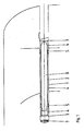
- Fig. 1 eine Anordnung mit einem abgestützten Innenrohr durch Feder-Schockdämpfungselemente,
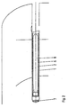
- Fig. 2 eine Anordnung gemäß Fig. 1 mit einer elastischen Abstützung über den gesamten Bereich des Innenraumes.
- Bei der dargestellten Anordnung ist in einem U-Boot ein Ablauf- bzw. Ausstoßrohr 1 ortsfest angeordnet. Für eine Führung eines Torpedos 8 ist ein zusätzliches Innenrohr 2 vorgesehen, das sich über in radialer und axialer Richtung arbeitende Feder-Schockdämpfungselemente 5 bzw. 6 zum eigentlichen Ablauf- bzw. Ausstoßrohr 1 elastisch abstützt.
- Der gebildete Ringraum 4 besitzt gemäß Fig. 1 einzelne Feder-Schockdämpfungselemente 5, während gemäß Fig. 2 der gesamte Bereich des Ringraumes 4 eine elastische Abstützung 6 aufweist.
- Hierbei sind die Ringräume über elastische Manschetten 3 bzw. durch die über die gesamte Länge des Innenrohres 2 angeordnete elastische Abstützung 6 selbst abgedichtet, so daß der Ringraum 4 auch im Zustand der Bewässerung bis zur maximalen Tauchtiefe des U-Bootes frei von Wasser gehalten wird und somit das Innenrohr 2 zusammen mit dem zu verbringenden Körper 8 zum Schockabbau unbehindert vom Wasser in radialer Richtung einfedern kann.
- Für den Schockabbau in axialer Richtung ist als elastischer Hohlkörper ein druckgasbeaufschlagter Schlauch 7 vorgesehen, der bei entsprechender Beanspruchung durch seine elastische Verformung für das vom zu verbringenden Körper 8 und Innenrohr 2 in axialer Richtung verdrängte Wasser entsprechenden Einfederungsfreiraum schafft.
Claims (2)
Applications Claiming Priority (2)
| Application Number | Priority Date | Filing Date | Title |
|---|---|---|---|
| DE3711059U | 1987-04-02 | ||
| DE3711059A DE3711059C1 (de) | 1987-04-02 | 1987-04-02 | Ausbildung von Ablauf-,Ausstossrohren oder Behaeltnissen in U-Booten |
Publications (2)
| Publication Number | Publication Date |
|---|---|
| EP0284777A1 EP0284777A1 (de) | 1988-10-05 |
| EP0284777B1 true EP0284777B1 (de) | 1990-08-08 |
Family
ID=6324682
Family Applications (1)
| Application Number | Title | Priority Date | Filing Date |
|---|---|---|---|
| EP88102778A Expired - Lifetime EP0284777B1 (de) | 1987-04-02 | 1988-02-25 | Ausbildung von Ablauf-, Ausstossrohren oder Behältnissen in U-Booten |
Country Status (3)
| Country | Link |
|---|---|
| US (1) | US4854260A (de) |
| EP (1) | EP0284777B1 (de) |
| DE (2) | DE3711059C1 (de) |
Families Citing this family (24)
| Publication number | Priority date | Publication date | Assignee | Title |
|---|---|---|---|---|
| US5003909A (en) * | 1990-06-18 | 1991-04-02 | The United States Of America As Represented By The Secretary Of The Navy | Submarine torpedo tube collapsible choke |
| US5231241A (en) * | 1992-06-29 | 1993-07-27 | The United States Of America As Represented By The Secretary Of The Navy | Elastomeric launcher |
| FR2724448B1 (fr) * | 1994-09-08 | 1996-12-27 | France Etat | Dispositif d'ejection d'une arme a partir d'un tube lance-armes immerge |
| FR2732106B1 (fr) * | 1995-03-20 | 1997-05-30 | France Etat | Conteneur securise pour munition autopropulsee notamment pour missile |
| US5666900A (en) * | 1995-06-05 | 1997-09-16 | Sippican, Inc. | Method and apparatus for deploying an expendable autonomous underwater vehicle from a submarine |
| US6330866B1 (en) * | 1998-05-22 | 2001-12-18 | The United States Of America As Represented By The Secretary Of The Navy | Missile support and alignment assembly |
| FR2781771B1 (fr) * | 1998-08-03 | 2001-02-09 | Mediterranee Const Ind | Procede de calage d'un tube dans un logement tubulaire, notamment d'un tube lance-missile |
| RU2148772C1 (ru) * | 1999-03-22 | 2000-05-10 | Государственное унитарное предприятие "Конструкторское бюро машиностроения" | Ракетно-торпедная пусковая установка |
| DE10031409C1 (de) * | 2000-06-28 | 2001-09-06 | Howaldtswerke Deutsche Werft | Lager- und Ausstoßbehälter für Unterwasserschwimm- und Tauchkörper |
| US6584924B2 (en) * | 2001-02-13 | 2003-07-01 | The United States Of America As Represented By The Secretary Of The Navy | Apparatus for controlling pressure recovery |
| RU2183173C1 (ru) * | 2001-02-14 | 2002-06-10 | Тихоокеанский военно-морской институт им. С.О. Макарова | Способ выпуска объекта из подводной лодки в подводном положении и устройство для его осуществления |
| US6701819B1 (en) * | 2002-08-19 | 2004-03-09 | The United States Of America As Represented By The Secretary Of The Navy | Apparatus for launching an object in a fluid environment |
| DE10332001B3 (de) * | 2003-07-14 | 2005-02-03 | Howaldtswerke - Deutsche Werft Ag | Schockdämpfungselement |
| DE102007004178B4 (de) | 2007-01-27 | 2009-01-29 | Howaldtswerke-Deutsche Werft Gmbh | Vorrichtung zum Lagern und Ausbringen von Tauchkörpern in einem Unterseeboot |
| DE102007041724B4 (de) | 2007-09-04 | 2017-11-23 | Thyssenkrupp Marine Systems Gmbh | Unterseeboot mit einem außen angeordneten Behälter |
| US8353239B1 (en) * | 2008-05-29 | 2013-01-15 | Lockheed Martin Corporation | Apparatus and method for directing the launch of a projectile |
| FR2975074B1 (fr) * | 2011-05-11 | 2013-06-21 | Dcns | Navire du type comportant au moins un puits de reception d'au moins un conteneur de lancement de missile |
| RU2606150C1 (ru) * | 2015-06-09 | 2017-01-10 | Федеральное государственное унитарное предприятие "Крыловский государственный научный центр" (ФГУП "Крыловский государственный научный центр") | Способ эксплуатации подводных аппаратов |
| DE102017210393B4 (de) | 2017-06-21 | 2023-06-22 | Thyssenkrupp Ag | Waffenrohr zur schockelastischen Aufnahme von Beladungen |
| DE102017222960B3 (de) | 2017-12-15 | 2019-05-02 | Thyssenkrupp Ag | Schocksichere Halterung einer Waffe in einem Waffenrohr |
| US11447219B2 (en) * | 2019-01-18 | 2022-09-20 | Advanced Acoustic Concepts, LLC | Weaponized UUV with floating barrel and externally accessible breech |
| US11041692B1 (en) * | 2020-05-12 | 2021-06-22 | Michael Chromych | System and method for launching and acceleration of objects |
| RU2748099C1 (ru) * | 2020-11-11 | 2021-05-19 | Федеральное государственное бюджетное учреждение науки Институт проблем морских технологий Дальневосточного отделения Российской академии наук (ИПМТ ДВО РАН) | Устройство для подводного пуска и приема автономного необитаемого подводного аппарата с борта судна-носителя |
| DE102023134636A1 (de) * | 2023-12-11 | 2025-06-12 | Thyssenkrupp Ag | Druckausstoß einer Waffe, welche sich in einem Container in einem Waffenrohr befindet |
Family Cites Families (11)
| Publication number | Priority date | Publication date | Assignee | Title |
|---|---|---|---|---|
| US1242768A (en) * | 1916-04-18 | 1917-10-09 | Edwin Cerio | Means for storing, loading, and discharging torpedoes. |
| US3088374A (en) * | 1960-11-28 | 1963-05-07 | John L Guyant | Inching and centering system |
| US3087386A (en) * | 1961-03-23 | 1963-04-30 | Robert D Rung | Adapter for missile launcher |
| US3224751A (en) * | 1964-05-15 | 1965-12-21 | Zenas B Andrews | Hydraulic cylinder-zero external volumetric change type |
| US3356056A (en) * | 1964-08-19 | 1967-12-05 | Lehmann Guenther Wolfgang | Submarine |
| US3266373A (en) * | 1964-10-27 | 1966-08-16 | Charles R Brown | Compact hold-down and vertical shock mount |
| US3392629A (en) * | 1965-06-25 | 1968-07-16 | Martin Marietta Corp | Shock resistant missile silo installation |
| US3301132A (en) * | 1965-07-29 | 1967-01-31 | Guenther W Lehmann | Submersible missile launching vehicle |
| US3732840A (en) * | 1970-12-14 | 1973-05-15 | E Dane | Ship sections adapted for disassembly and re-assembly at sea |
| DE2454738C2 (de) * | 1974-11-19 | 1982-09-30 | Krupp Mak Maschinenbau Gmbh, 2300 Kiel | Röhrenförmiger Behälter für Schwimm- und Tauchkörper |
| DE2455994C3 (de) * | 1974-11-27 | 1980-01-10 | Mak Maschinenbau Gmbh, 2300 Kiel | Vorrichtung zum Ausstoßen bzw. Ablaufen von Tauch- und Schwimmkörpern aus Rohren |
-
1987
- 1987-04-02 DE DE3711059A patent/DE3711059C1/de not_active Expired
-
1988
- 1988-02-25 DE DE8888102778T patent/DE3860408D1/de not_active Revoked
- 1988-02-25 EP EP88102778A patent/EP0284777B1/de not_active Expired - Lifetime
- 1988-03-29 US US07/174,767 patent/US4854260A/en not_active Expired - Fee Related
Also Published As
| Publication number | Publication date |
|---|---|
| DE3711059C1 (de) | 1988-10-13 |
| DE3860408D1 (de) | 1990-09-13 |
| EP0284777A1 (de) | 1988-10-05 |
| US4854260A (en) | 1989-08-08 |
Similar Documents
| Publication | Publication Date | Title |
|---|---|---|
| EP0284777B1 (de) | Ausbildung von Ablauf-, Ausstossrohren oder Behältnissen in U-Booten | |
| DE69508681T2 (de) | Vorrichtung zum Ausstoss eines Torpedos aus einer Unterwasserstartvorrichtung | |
| DE1103813B (de) | Geschoss fuer Granatwerfer | |
| DE3048666C2 (de) | Autarke Ausstoßeinrichtung für Lenkwaffen | |
| DE69120954T2 (de) | Vorrichtung zum abfeuern eines geschosses | |
| DE2424480A1 (de) | Behaelter und abschussrohr fuer eine rakete | |
| DE3715085A1 (de) | Flugkörper-Spitzenverkleidungsaufbau | |
| DE4401315B4 (de) | Vorrichtung zur Flugbahnkorrektur | |
| DE3643197A1 (de) | Zieleinrichtung eines waffenrohres | |
| EP1078849A2 (de) | Stau- und Transporteinrichtung für in Torpedorohre zu verbringende Körper | |
| DE1009067B (de) | Treibspiegel fuer unterkalibrige, drallose Wurfminen | |
| DE2654827A1 (de) | Mittels eines traegergeschosses verschiessbare hohlladungstochtergeschosse | |
| DE19644524A1 (de) | Geschützturm für Panzerfahrzeuge | |
| DE2822355A1 (de) | Transport- und abschussbehaelter | |
| DE2627505A1 (de) | Vorrichtung zur lagerung, zum transport und abschuss von flugkoerpern | |
| DE10338184B4 (de) | Mörsergranate | |
| DE1678492B1 (de) | Granatwerfer-UEbungsgeschoss | |
| DE3609864B3 (de) | Hohlladungsgeschoß | |
| DE2426838B2 (de) | Aufschlagzünder | |
| DE3118403C2 (de) | "Vorrichtung zum lösbaren Verriegeln einer Granate in einem kombinierten Geschoß" | |
| DE102012206709B4 (de) | Unterseeboot | |
| DE19806958B4 (de) | Geschoßkopf | |
| DE102019203071B4 (de) | Brückenlose Waffenmulde | |
| DE2853527C2 (de) | Abschußvorrichtung für Geschosse | |
| DE267962C (de) |
Legal Events
| Date | Code | Title | Description |
|---|---|---|---|
| PUAI | Public reference made under article 153(3) epc to a published international application that has entered the european phase |
Free format text: ORIGINAL CODE: 0009012 |
|
| AK | Designated contracting states |
Kind code of ref document: A1 Designated state(s): DE FR GB IT NL SE |
|
| 17P | Request for examination filed |
Effective date: 19881014 |
|
| 17Q | First examination report despatched |
Effective date: 19890227 |
|
| GRAA | (expected) grant |
Free format text: ORIGINAL CODE: 0009210 |
|
| AK | Designated contracting states |
Kind code of ref document: B1 Designated state(s): DE FR GB IT NL SE |
|
| REF | Corresponds to: |
Ref document number: 3860408 Country of ref document: DE Date of ref document: 19900913 |
|
| ITF | It: translation for a ep patent filed | ||
| ET | Fr: translation filed | ||
| GBT | Gb: translation of ep patent filed (gb section 77(6)(a)/1977) | ||
| PGFP | Annual fee paid to national office [announced via postgrant information from national office to epo] |
Ref country code: FR Payment date: 19910221 Year of fee payment: 4 |
|
| PGFP | Annual fee paid to national office [announced via postgrant information from national office to epo] |
Ref country code: NL Payment date: 19910228 Year of fee payment: 4 |
|
| PLBI | Opposition filed |
Free format text: ORIGINAL CODE: 0009260 |
|
| 26 | Opposition filed |
Opponent name: CONSTRUCTIONS INDUSTRIELLES DE LA MEDITERRANEE - C Effective date: 19910506 |
|
| PGFP | Annual fee paid to national office [announced via postgrant information from national office to epo] |
Ref country code: SE Payment date: 19910719 Year of fee payment: 4 |
|
| NLR1 | Nl: opposition has been filed with the epo |
Opponent name: CONSTRUCTIONS INDUSTRIELLES DE LA MEDITERRANEE-CNI |
|
| RAP2 | Party data changed (patent owner data changed or rights of a patent transferred) |
Owner name: HOWALDTSWERKE-DEUTSCHE WERFT AG |
|
| NLT2 | Nl: modifications (of names), taken from the european patent patent bulletin |
Owner name: HOWALDTSWERKE-DEUTSCHE WERFT AKTIENGESELLSCHAFT TE |
|
| PLAB | Opposition data, opponent's data or that of the opponent's representative modified |
Free format text: ORIGINAL CODE: 0009299OPPO |
|
| ITTA | It: last paid annual fee | ||
| PGFP | Annual fee paid to national office [announced via postgrant information from national office to epo] |
Ref country code: DE Payment date: 19920304 Year of fee payment: 5 |
|
| R26 | Opposition filed (corrected) |
Opponent name: CONSTRUCTIONS INDUSTRIELLES DE LA MEDITERRANEE - C Effective date: 19910506 |
|
| RDAG | Patent revoked |
Free format text: ORIGINAL CODE: 0009271 |
|
| STAA | Information on the status of an ep patent application or granted ep patent |
Free format text: STATUS: PATENT REVOKED |
|
| 27W | Patent revoked |
Effective date: 19920421 |
|
| GBPR | Gb: patent revoked under art. 102 of the ep convention designating the uk as contracting state | ||
| NLR2 | Nl: decision of opposition | ||
| EUG | Se: european patent has lapsed |
Ref document number: 88102778.3 Effective date: 19920904 |