EP0284812A1 - Dispositif pour transporter des feuilles, par exemple des feuilles en papier - Google Patents
Dispositif pour transporter des feuilles, par exemple des feuilles en papier Download PDFInfo
- Publication number
- EP0284812A1 EP0284812A1 EP88103262A EP88103262A EP0284812A1 EP 0284812 A1 EP0284812 A1 EP 0284812A1 EP 88103262 A EP88103262 A EP 88103262A EP 88103262 A EP88103262 A EP 88103262A EP 0284812 A1 EP0284812 A1 EP 0284812A1
- Authority
- EP
- European Patent Office
- Prior art keywords
- ball
- sheet
- transport
- head
- friction
- Prior art date
- Legal status (The legal status is an assumption and is not a legal conclusion. Google has not performed a legal analysis and makes no representation as to the accuracy of the status listed.)
- Granted
Links
- 238000005096 rolling process Methods 0.000 claims description 6
- 238000012546 transfer Methods 0.000 claims description 3
- 238000013461 design Methods 0.000 description 2
- 238000006073 displacement reaction Methods 0.000 description 2
- 230000005484 gravity Effects 0.000 description 2
- 238000011161 development Methods 0.000 description 1
- 230000018109 developmental process Effects 0.000 description 1
- 230000000694 effects Effects 0.000 description 1
- 230000002349 favourable effect Effects 0.000 description 1
- 238000012986 modification Methods 0.000 description 1
- 230000004048 modification Effects 0.000 description 1
- 238000005457 optimization Methods 0.000 description 1
- 238000012545 processing Methods 0.000 description 1
- 238000012549 training Methods 0.000 description 1
- 238000011144 upstream manufacturing Methods 0.000 description 1
Images


Classifications
-
- B—PERFORMING OPERATIONS; TRANSPORTING
- B65—CONVEYING; PACKING; STORING; HANDLING THIN OR FILAMENTARY MATERIAL
- B65H—HANDLING THIN OR FILAMENTARY MATERIAL, e.g. SHEETS, WEBS, CABLES
- B65H3/00—Separating articles from piles
- B65H3/08—Separating articles from piles using pneumatic force
- B65H3/10—Suction rollers
-
- B—PERFORMING OPERATIONS; TRANSPORTING
- B65—CONVEYING; PACKING; STORING; HANDLING THIN OR FILAMENTARY MATERIAL
- B65H—HANDLING THIN OR FILAMENTARY MATERIAL, e.g. SHEETS, WEBS, CABLES
- B65H3/00—Separating articles from piles
- B65H3/08—Separating articles from piles using pneumatic force
- B65H3/12—Suction bands, belts, or tables moving relatively to the pile
- B65H3/122—Suction tables
-
- B—PERFORMING OPERATIONS; TRANSPORTING
- B65—CONVEYING; PACKING; STORING; HANDLING THIN OR FILAMENTARY MATERIAL
- B65H—HANDLING THIN OR FILAMENTARY MATERIAL, e.g. SHEETS, WEBS, CABLES
- B65H3/00—Separating articles from piles
- B65H3/46—Supplementary devices or measures to assist separation or prevent double feed
- B65H3/48—Air blast acting on edges of, or under, articles
-
- B—PERFORMING OPERATIONS; TRANSPORTING
- B65—CONVEYING; PACKING; STORING; HANDLING THIN OR FILAMENTARY MATERIAL
- B65H—HANDLING THIN OR FILAMENTARY MATERIAL, e.g. SHEETS, WEBS, CABLES
- B65H2301/00—Handling processes for sheets or webs
- B65H2301/40—Type of handling process
- B65H2301/42—Piling, depiling, handling piles
- B65H2301/423—Depiling; Separating articles from a pile
- B65H2301/4232—Depiling; Separating articles from a pile of horizontal or inclined articles, i.e. wherein articles support fully or in part the mass of other articles in the piles
- B65H2301/42324—Depiling; Separating articles from a pile of horizontal or inclined articles, i.e. wherein articles support fully or in part the mass of other articles in the piles from top of the pile
Definitions
- the invention relates to a device for transporting sheets according to the preamble of the main claim.
- Such devices are arranged upstream of sheet-fed printing machines in order to lift and deposit the sheets from a sheet stack by means of reciprocating transport heads, with the result that the sheets are fed in a scale-like manner.
- the transport route depends on the path of the transport head.
- the invention has for its object to design a device of the type in question in a technically simple manner so that, with optimization of the conveying behavior by means of the transport head, differently sized sheet conveying paths can optionally be covered with a selectable direction.
- a device of the type in question is created with an enlarged range of use.
- sheet transport paths of different sizes can be achieved using one and the same transport head.
- the transport head itself does not carry out a transport movement. It is always above the sheet stack.
- this presupposes that the frictional force is greater than the suction force in order to be able to take the sheet along when the rolling body rotates.
- the corresponding arc path can be determined, for example, by the respective drive duration.
- the rolling elements themselves can have different shapes. They can be roller or barrel shaped. In particular, training as a ball is recommended.
- the dome protruding over the arch contact surface of the transport head, the ball rotatably mounted in all directions about its fixed center point, the arch can even be shifted in its plane in any direction. The direction of movement of the arc then coincides with the plane of rotation of the ball.
- the displacement of the sheet can be carried out in all different directions. This makes it possible to automatically correct the position of the sheets in the stack.
- both friction wheel drives set the ball in rotation at the same time, this leads to a diagonal displacement of the bow to its original orientation.
- the angle of the diagonal course can are varied by the independently provided speed control. For example, the angle for diagonally conveying the sheet at the same speed of the friction wheel drives and friction wheel diameters of the same size is 45 °. If the sheet is scanned without contact, for example optically, and this is passed on via a computer as a command to control the speed of the friction wheel drives, this results in the possibility of an optimal, gentle transport of sheets in very specific alignment positions, for example a processing machine, for example a printing machine.
- the friction between the dome of the ball and the top of the arch is increased by the suction gap provided between the dome and the arch contact surface passage hole, which in turn is connected to the vacuum source.
- the friction between the arch and the ball-dome can be varied by appropriately dimensioning the negative pressure.
- Another way to vary the friction between the dome and the arch is to provide the ball surface with suction holes and to connect the inside of the ball to the vacuum source.
- the ball itself can be made from different materials. However, it is particularly useful to design the ball as an elastic ball.
- a protrusion of approximately 1.5 mm from the dome over the arch contact surface is preferably sufficient to achieve good entrainment of the arch.
- a structurally favorable solution to connect the annular gap and also the inside of the ball to the vacuum source consists in accommodating the ball, including its storage, in the vacuum chamber. This forms the transport head in connection with the ball and the friction wheel drives.
- the air devices arranged at a distance from the ball are used suction openings, so that the sheet is in full contact with the sheet contact surface.
- the suction force counteracts the gravity of the bow.
- the suction force is dimensioned so that the force of the frictional connection between ball and arc is greater.
- the friction wheel drives can be controlled via a computer.
- the entrainment of the arc in the plane of rotation of the ball is improved by a corresponding friction lining of the ball surface.
- the sheet path can advantageously be enlarged by a plurality of transport heads which are arranged in a row in the transport direction and a transfer of the sheet from head to head. The promotion of the sheets is very gentle here too.
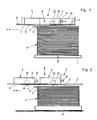
- the numeral 1 denotes a carrier which can be displaced in the vertical direction for receiving a sheet stack 2. Above the same extends a stationary device 3 for removing the uppermost sheet 4 and further transporting it in the horizontal direction x.
- a loosening blower 6 is provided on the upper stack edge 5 lying transversely to the conveying direction x.
- the device 4 includes a horizontal support 7 with a downward-pointing transport head 8 extending therefrom.
- the latter has a vacuum chamber 9 which is covered on the underside by a closure plate 10.
- the same fits through an opening 11 of a plate 13 aligned parallel to the horizontal support 7 and forming the sheet contact surface 12.
- the closure plate 10 thus also forms part of the sheet contact surface 12.
- the vacuum chamber 9 is composed of a ceiling wall 14, the side walls 15, 16, 17, 18 which extend downward from this and the closure plate 10 which engages under the side walls.
- One side wall 18 carries a connecting piece 19 which is connected to a vacuum source via a line (not shown) is connectable.
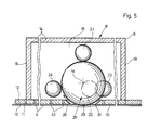
- a ball 10 rotates in all directions about its fixed center M by means of four bearing balls 21, 22, 23, 24 placed on the ball surface.
- the latter are rotatably seated in lugs 25, 26, 27, 28 that extend from the ceiling wall 14.
- the bearing ball 21 carried by the lug 25 extends perpendicularly above the center point M of the ball 20.
- the remaining three bearing balls 22, 23, 24 are provided in the same circumferential distribution as the ball 20, extend on a common horizontal plane and rest on the spherical surface of the lower one Half of the ball on with the ball 20 in the layered position.
- the lugs and the bearing balls are arranged in such a way that the ball 20 is kept free of play.
- the ball 20 forms a dome 29 protruding over the curved contact surface 12 of the transport head 8. Its board is approximately 1.5 mm. So that the dome 29 can project beyond the arch contact surface 12 at all, a passage hole 30 is provided in the closure plate 10. A suction gap 31 is formed between this and the spherical surface lying at the same height.
- the ball 20 is driven by two friction wheel drives 32, 33 which are at right angles to one another and have drive axes y, z of the friction wheels 34, 35 which are at right angles to one another.
- the drive axes y, z run horizontally and extend at the level of the center M of the ball 20. Furthermore, the orientation of the drive axis z is such that it runs in the conveying direction x.
- Each friction wheel drive 32, 33 engages at the center of the ball 20 on its ball surface and contains a DC motor 36, 37. The latter sit on bearing blocks 38, 39 starting from the ceiling wall 14.
- the diameters of the friction wheels 34, 35 are the same size.
- the friction wheels 34, 35 are provided with a friction lining on their circumference in order to enable the ball 20 to be taken along without slipping.
- the device operates as follows: In order to remove the uppermost sheet 4 from the sheet stack 2, the sheet stack carrier 1 is moved close to the transport head 8. Supported by the loosening blower 6, the transport head 8 can suck in the uppermost sheet according to FIG. 1 via the suction gap 31, whereby it comes into contact with the sheet contact surface 12. Now only the friction wheel drive 32 with its drive axis running transverse to the conveying direction x is shuttered tet, the plane of rotation of the ball 20 is aligned with the direction of conveyance and accordingly moves the arc in this direction, compare dash-dotted representation of the arc 4 ⁇ in Fig. 1.
- the suction force exerted on the arch 4 is less than the force of the frictional connection between the arch 4 and the dome 29, so that the arch is always moved in the corresponding direction when the ball 20 rotates.
- the ball 20 is preferably designed as an elastic ball and provided with a corresponding friction lining. As a result, the entrainment of the sheet is improved.
- the entrainment behavior can also be varied by the projection of the dome 29 over the arch contact surface 12. Furthermore, a variation by the size of the suction gap 31 and dimensioning of the negative pressure is possible.
- the same components have the same reference numbers.
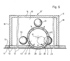
- the ball 41 has suction holes 42 arranged in the same distribution in its ball surface.
- the vacuum chamber 9 comprising the ball 41
- the ball interior 43 is also connected to the vacuum source. The suction air can accordingly become effective on the one hand through the suction gap 31 on the top of the arch 4 and on the other hand through the suction holes 42 in the region of the dome 29.
- a stationary carrier 44 is used for receiving the sheet stack 2. Furthermore, two transport heads 8, which are located one behind the other in the transport direction x, are provided in order to be able to transfer the sheet 4 lying on top from head to head, compare sheet 4 ⁇ shown in dash-dot lines in FIG. 2. The structure of the transport heads 8 corresponds to that described above.
- the device 3 ⁇ can now be displaced in the vertical direction.
- the sheets can be moved deviating from the conveying direction x by correspondingly driving the ball 20.
Landscapes
- Engineering & Computer Science (AREA)
- Mechanical Engineering (AREA)
- Sheets, Magazines, And Separation Thereof (AREA)
Applications Claiming Priority (2)
| Application Number | Priority Date | Filing Date | Title |
|---|---|---|---|
| DE3710258 | 1987-03-28 | ||
| DE19873710258 DE3710258A1 (de) | 1987-03-28 | 1987-03-28 | Vorrichtung zum transport von bogen, beispielsweise papierbogen |
Publications (2)
| Publication Number | Publication Date |
|---|---|
| EP0284812A1 true EP0284812A1 (fr) | 1988-10-05 |
| EP0284812B1 EP0284812B1 (fr) | 1991-05-29 |
Family
ID=6324209
Family Applications (1)
| Application Number | Title | Priority Date | Filing Date |
|---|---|---|---|
| EP88103262A Expired - Lifetime EP0284812B1 (fr) | 1987-03-28 | 1988-03-03 | Dispositif pour transporter des feuilles, par exemple des feuilles en papier |
Country Status (7)
| Country | Link |
|---|---|
| US (1) | US4909500A (fr) |
| EP (1) | EP0284812B1 (fr) |
| JP (1) | JPS63258333A (fr) |
| CN (1) | CN1018067B (fr) |
| AU (1) | AU604531B2 (fr) |
| CA (1) | CA1298327C (fr) |
| DE (2) | DE3710258A1 (fr) |
Cited By (2)
| Publication number | Priority date | Publication date | Assignee | Title |
|---|---|---|---|---|
| EP0387476A1 (fr) * | 1989-03-17 | 1990-09-19 | Guy Martin | Dispositif de prise de feuilles planes avec déramage à flux d'air turbulent |
| EP2322293A1 (fr) * | 2009-11-13 | 2011-05-18 | Renner GmbH | Dispositif et procédé d'enlèvement d'étiquettes d'objets |
Families Citing this family (14)
| Publication number | Priority date | Publication date | Assignee | Title |
|---|---|---|---|---|
| DE3804576A1 (de) * | 1987-03-28 | 1988-10-06 | Heidelberger Druckmasch Ag | Vorrichtung zum foerdern und ausrichten von bogen bei bogenverarbeitenden maschinen |
| CH678413A5 (fr) * | 1988-10-12 | 1991-09-13 | Bobst Sa | |
| CH692245A5 (fr) * | 1998-01-20 | 2002-04-15 | Bobst Sa | Dispositif et module d'alimentation pour matériau en bande. |
| DE19906697A1 (de) * | 1999-02-18 | 2000-08-24 | Nfw Wilsmann Elektronik Gmbh | Positionier- und/oder Fördervorrichtung von Flach- und Wickelgut |
| US6241242B1 (en) * | 1999-10-12 | 2001-06-05 | Hewlett-Packard Company | Deskew of print media |
| US6926271B2 (en) * | 2002-02-15 | 2005-08-09 | Lockheed Martin Corporation | Flat mail edge biasing machine and method of use |
| CN100393940C (zh) * | 2006-04-21 | 2008-06-11 | 中国印钞造币总公司 | 内嵌特征物防伪纸的制备方法及特征物施放装置 |
| JP5441682B2 (ja) * | 2009-12-28 | 2014-03-12 | キヤノン株式会社 | シート搬送装置及び画像形成装置 |
| CN104709515B (zh) * | 2015-03-04 | 2016-11-02 | 重庆烟草工业有限责任公司涪陵卷烟厂 | 预切式内框纸输送装置 |
| JP7082455B2 (ja) * | 2015-10-20 | 2022-06-08 | サクラ精機株式会社 | ワーク搬送装置 |
| US10584009B1 (en) * | 2019-08-02 | 2020-03-10 | Capital One Services, Llc | Sheet orienting apparatus using ball drive |
| CN116568619A (zh) * | 2020-11-19 | 2023-08-08 | 鲍勃斯脱里昂公司 | 具有反转传送模块的转换机 |
| CN112959741A (zh) * | 2021-03-04 | 2021-06-15 | 涡阳县利达塑料包装制品有限公司 | 一种可靠稳定的塑编袋输送装置 |
| CN119683370A (zh) * | 2025-02-27 | 2025-03-25 | 温州永邦机械有限公司 | 一种裱纸机免压力送纸机构 |
Citations (1)
| Publication number | Priority date | Publication date | Assignee | Title |
|---|---|---|---|---|
| GB1303056A (fr) * | 1969-09-19 | 1973-01-17 |
Family Cites Families (19)
| Publication number | Priority date | Publication date | Assignee | Title |
|---|---|---|---|---|
| DE830344C (de) * | 1950-06-30 | 1952-02-04 | Georg Spiess Dr Ing | Foerdertisch |
| DE1253728B (de) * | 1966-05-05 | 1967-11-09 | Arno Jaatinen Dipl Ing | Vorrichtung zum Entfernen des jeweils obersten Bogens eines aus nahezu luftundurchlaessigen Bogen bestehenden Stapels |
| US3610714A (en) * | 1970-01-02 | 1971-10-05 | Albert M De Gaeta | Ball bearing |
| DD96461A1 (fr) * | 1972-05-29 | 1973-03-20 | ||
| DE2229814A1 (de) * | 1972-06-19 | 1973-11-29 | Gremser Masch Franz | Vorstapeleinrichtung an bogenanlegern |
| US3908986A (en) * | 1973-06-15 | 1975-09-30 | Ibm | Sheet aligning mechanism |
| JPS527568A (en) * | 1975-07-05 | 1977-01-20 | Hashimoto Denki Co Ltd | Apparatus for automatically aligning and paying-off thin plate |
| DE2647841C3 (de) * | 1976-10-22 | 1981-05-14 | Rapicom Inc., Fairfield, N.J. | Vorrichtung zum Vereinzeln des obersten Blattes eines Blattstapels |
| JPS5418578A (en) * | 1977-07-11 | 1979-02-10 | Ricoh Co Ltd | Pneumatic sheet feeding apparatus |
| JPS5570644A (en) * | 1978-11-21 | 1980-05-28 | Ricoh Co Ltd | Air type sheet feeder |
| US4266762A (en) * | 1979-08-29 | 1981-05-12 | Xerox Corporation | Sheet alignment and feeding apparatus |
| US4381212A (en) * | 1980-02-20 | 1983-04-26 | Molins Machine Company, Inc. | Fingerless single facer |
| US4614335A (en) * | 1980-04-28 | 1986-09-30 | Wm. C. Staley Machinery Corporation | Intermittently protruding feeder for paperboard blanks |
| JPS57184034A (en) * | 1981-05-08 | 1982-11-12 | Canon Inc | Air-suction feeder |
| JPS57199738A (en) * | 1981-06-03 | 1982-12-07 | Ricoh Co Ltd | Paper feeding unit of copying machine |
| US4411418A (en) * | 1982-02-12 | 1983-10-25 | Xerox Corporation | Document corner registration |
| JPS60223748A (ja) * | 1984-04-20 | 1985-11-08 | Fujitsu Ltd | 紙葉類搬送装置 |
| EP0216644B1 (fr) * | 1985-08-02 | 1989-09-27 | Bertin & Cie | Ensemble de guidage de feuilles de matériau souple destinées à former un assemblage tridimensionnel |
| US4669718A (en) * | 1986-02-14 | 1987-06-02 | Herman Rovin | Bi-directional actuator |
-
1987
- 1987-03-28 DE DE19873710258 patent/DE3710258A1/de active Granted
-
1988
- 1988-03-01 CA CA000560266A patent/CA1298327C/fr not_active Expired - Lifetime
- 1988-03-03 EP EP88103262A patent/EP0284812B1/fr not_active Expired - Lifetime
- 1988-03-03 DE DE8888103262T patent/DE3862977D1/de not_active Expired - Lifetime
- 1988-03-07 AU AU12668/88A patent/AU604531B2/en not_active Ceased
- 1988-03-25 CN CN88101355A patent/CN1018067B/zh not_active Expired
- 1988-03-28 JP JP63072161A patent/JPS63258333A/ja active Pending
- 1988-03-28 US US07/174,087 patent/US4909500A/en not_active Expired - Fee Related
Patent Citations (1)
| Publication number | Priority date | Publication date | Assignee | Title |
|---|---|---|---|---|
| GB1303056A (fr) * | 1969-09-19 | 1973-01-17 |
Cited By (2)
| Publication number | Priority date | Publication date | Assignee | Title |
|---|---|---|---|---|
| EP0387476A1 (fr) * | 1989-03-17 | 1990-09-19 | Guy Martin | Dispositif de prise de feuilles planes avec déramage à flux d'air turbulent |
| EP2322293A1 (fr) * | 2009-11-13 | 2011-05-18 | Renner GmbH | Dispositif et procédé d'enlèvement d'étiquettes d'objets |
Also Published As
| Publication number | Publication date |
|---|---|
| CN1018067B (zh) | 1992-09-02 |
| CN88101355A (zh) | 1988-10-19 |
| DE3710258C2 (fr) | 1990-02-15 |
| DE3862977D1 (de) | 1991-07-04 |
| US4909500A (en) | 1990-03-20 |
| JPS63258333A (ja) | 1988-10-25 |
| AU1266888A (en) | 1988-09-29 |
| AU604531B2 (en) | 1990-12-20 |
| CA1298327C (fr) | 1992-03-31 |
| EP0284812B1 (fr) | 1991-05-29 |
| DE3710258A1 (de) | 1988-10-13 |
Similar Documents
| Publication | Publication Date | Title |
|---|---|---|
| EP0284812B1 (fr) | Dispositif pour transporter des feuilles, par exemple des feuilles en papier | |
| EP0284806B1 (fr) | Tête aspirante avec ventouses de levage | |
| DE68909954T2 (de) | Stapelvorrichtung. | |
| DE102004003509A1 (de) | Vorrichtung zum Fördern von Bogen | |
| EP0364837A1 (fr) | Dispositif d'étiquetage pour opposer une étiquette sur un support, en particulier une étiquette de grand format sur un rouleau de papier ainsi que méthode d'application | |
| DE4444963C2 (de) | Verfahren zum Entstapeln von nichtferromagnetischen Platinen und Einrichtung zur Durchführung des Verfahrens | |
| DE3804576A1 (de) | Vorrichtung zum foerdern und ausrichten von bogen bei bogenverarbeitenden maschinen | |
| EP0683126B1 (fr) | Procédé et appareil d'approvisionnement d'une pile de feuille à une machine à imprimer | |
| DE4220396C2 (de) | Bogenleiteinrichtung für Bogenanleger mit Vorderkantentrennern | |
| DE976134C (de) | Bogenanlegevorrichtung fuer Druck- und andere Bogenverarbeitungsmaschinen | |
| DE2457069C2 (de) | Vorrichtung zum passergerechten Anlegen von Bogen in Bogenrotationsdruckmaschinen | |
| DE4234184C2 (de) | Hubsauger zum Anheben eines Papierbogens vom Stapel und zum Halten des Bogens in der angehobenen Position oberhalb des Stapels | |
| DE1929290C3 (de) | Vorrichtung zur Entnahme gestapelter Bogen aus Pappe, Wellpappe od. dgl | |
| DE3424815A1 (de) | Blaseinrichtung zum vereinzeln von bogen in bogenanlegern | |
| DE4016304A1 (de) | Vorrichtung zum ausrichten schuppenfoermig unterlappt gefoerderter bogen | |
| DE69007077T2 (de) | Maschine zum Entstapeln von Platten, insbesondere von Glasscheiben mit geschliffenen schrägen oder abgerundeten Kanten. | |
| EP0037427B1 (fr) | Margeur comportant un dispositif réglable en hauteur supportant la pile de feuilles à imprimer par une machine rotative | |
| EP1593626A1 (fr) | Margeur du bord avant | |
| EP0775657A2 (fr) | Dispositif pour aligner des objets postaux plats | |
| DE3418258A1 (de) | Vorrichtung zur abnahme von beschichtungsfolien von einem beschichtungsfolienstapel sowie zur ablage auf einem zusammenlegetisch | |
| DE2222066C2 (de) | Saugfuß-Trenn- und Abziehvorrichtung | |
| DE4214232C1 (de) | Bogenanleger mit im bereich der stapelhinterkante angeordneten trennsaugern | |
| DE923132C (de) | Vorrichtung zum Vereinzeln und zum Zufuehren von Bogen aus Papier usw. an Druck-, Lackier- und Falzmaschinen | |
| DE29705707U1 (de) | Vorrichtung zum Handling von Leiterplatten | |
| DE102020210425B4 (de) | Transportvorrichtung zum Transport und zur Ablage von Dünnschichtelementen und Verfahren |
Legal Events
| Date | Code | Title | Description |
|---|---|---|---|
| PUAI | Public reference made under article 153(3) epc to a published international application that has entered the european phase |
Free format text: ORIGINAL CODE: 0009012 |
|
| 17P | Request for examination filed |
Effective date: 19880303 |
|
| AK | Designated contracting states |
Kind code of ref document: A1 Designated state(s): CH DE FR GB IT LI SE |
|
| 17Q | First examination report despatched |
Effective date: 19900420 |
|
| GRAA | (expected) grant |
Free format text: ORIGINAL CODE: 0009210 |
|
| AK | Designated contracting states |
Kind code of ref document: B1 Designated state(s): CH DE FR GB IT LI SE |
|
| REF | Corresponds to: |
Ref document number: 3862977 Country of ref document: DE Date of ref document: 19910704 |
|
| ET | Fr: translation filed | ||
| ITF | It: translation for a ep patent filed | ||
| GBT | Gb: translation of ep patent filed (gb section 77(6)(a)/1977) | ||
| PGFP | Annual fee paid to national office [announced via postgrant information from national office to epo] |
Ref country code: SE Payment date: 19920316 Year of fee payment: 5 |
|
| PLBE | No opposition filed within time limit |
Free format text: ORIGINAL CODE: 0009261 |
|
| STAA | Information on the status of an ep patent application or granted ep patent |
Free format text: STATUS: NO OPPOSITION FILED WITHIN TIME LIMIT |
|
| 26N | No opposition filed | ||
| PG25 | Lapsed in a contracting state [announced via postgrant information from national office to epo] |
Ref country code: SE Effective date: 19930304 |
|
| PGFP | Annual fee paid to national office [announced via postgrant information from national office to epo] |
Ref country code: FR Payment date: 19930305 Year of fee payment: 6 |
|
| PGFP | Annual fee paid to national office [announced via postgrant information from national office to epo] |
Ref country code: CH Payment date: 19930526 Year of fee payment: 6 |
|
| PGFP | Annual fee paid to national office [announced via postgrant information from national office to epo] |
Ref country code: GB Payment date: 19940221 Year of fee payment: 7 |
|
| PG25 | Lapsed in a contracting state [announced via postgrant information from national office to epo] |
Ref country code: LI Effective date: 19940331 Ref country code: CH Effective date: 19940331 |
|
| PG25 | Lapsed in a contracting state [announced via postgrant information from national office to epo] |
Ref country code: FR Effective date: 19941130 |
|
| REG | Reference to a national code |
Ref country code: CH Ref legal event code: PL |
|
| REG | Reference to a national code |
Ref country code: FR Ref legal event code: ST |
|
| EUG | Se: european patent has lapsed |
Ref document number: 88103262.7 Effective date: 19931008 |
|
| PG25 | Lapsed in a contracting state [announced via postgrant information from national office to epo] |
Ref country code: GB Effective date: 19950303 |
|
| GBPC | Gb: european patent ceased through non-payment of renewal fee |
Effective date: 19950303 |
|
| PGFP | Annual fee paid to national office [announced via postgrant information from national office to epo] |
Ref country code: DE Payment date: 19970423 Year of fee payment: 10 |
|
| PG25 | Lapsed in a contracting state [announced via postgrant information from national office to epo] |
Ref country code: DE Free format text: LAPSE BECAUSE OF NON-PAYMENT OF DUE FEES Effective date: 19981201 |
|
| PG25 | Lapsed in a contracting state [announced via postgrant information from national office to epo] |
Ref country code: IT Free format text: LAPSE BECAUSE OF NON-PAYMENT OF DUE FEES;WARNING: LAPSES OF ITALIAN PATENTS WITH EFFECTIVE DATE BEFORE 2007 MAY HAVE OCCURRED AT ANY TIME BEFORE 2007. THE CORRECT EFFECTIVE DATE MAY BE DIFFERENT FROM THE ONE RECORDED. Effective date: 20050303 |