EP0284848A2 - Process for making a honeycomb core for a sandwich panel - Google Patents
Process for making a honeycomb core for a sandwich panel Download PDFInfo
- Publication number
- EP0284848A2 EP0284848A2 EP88103674A EP88103674A EP0284848A2 EP 0284848 A2 EP0284848 A2 EP 0284848A2 EP 88103674 A EP88103674 A EP 88103674A EP 88103674 A EP88103674 A EP 88103674A EP 0284848 A2 EP0284848 A2 EP 0284848A2
- Authority
- EP
- European Patent Office
- Prior art keywords
- grid
- stack
- bars
- gitters
- eines
- Prior art date
- Legal status (The legal status is an assumption and is not a legal conclusion. Google has not performed a legal analysis and makes no representation as to the accuracy of the status listed.)
- Withdrawn
Links
Images
Classifications
-
- B—PERFORMING OPERATIONS; TRANSPORTING
- B32—LAYERED PRODUCTS
- B32B—LAYERED PRODUCTS, i.e. PRODUCTS BUILT-UP OF STRATA OF FLAT OR NON-FLAT, e.g. CELLULAR OR HONEYCOMB, FORM
- B32B37/00—Methods or apparatus for laminating, e.g. by curing or by ultrasonic bonding
- B32B37/14—Methods or apparatus for laminating, e.g. by curing or by ultrasonic bonding characterised by the properties of the layers
- B32B37/146—Methods or apparatus for laminating, e.g. by curing or by ultrasonic bonding characterised by the properties of the layers whereby one or more of the layers is a honeycomb structure
-
- B—PERFORMING OPERATIONS; TRANSPORTING
- B32—LAYERED PRODUCTS
- B32B—LAYERED PRODUCTS, i.e. PRODUCTS BUILT-UP OF STRATA OF FLAT OR NON-FLAT, e.g. CELLULAR OR HONEYCOMB, FORM
- B32B3/00—Layered products comprising a layer with external or internal discontinuities or unevennesses, or a layer of non-planar shape; Layered products comprising a layer having particular features of form
- B32B3/10—Layered products comprising a layer with external or internal discontinuities or unevennesses, or a layer of non-planar shape; Layered products comprising a layer having particular features of form characterised by a discontinuous layer, i.e. formed of separate pieces of material
- B32B3/12—Layered products comprising a layer with external or internal discontinuities or unevennesses, or a layer of non-planar shape; Layered products comprising a layer having particular features of form characterised by a discontinuous layer, i.e. formed of separate pieces of material characterised by a layer of regularly- arranged cells, e.g. a honeycomb structure
-
- B—PERFORMING OPERATIONS; TRANSPORTING
- B32—LAYERED PRODUCTS
- B32B—LAYERED PRODUCTS, i.e. PRODUCTS BUILT-UP OF STRATA OF FLAT OR NON-FLAT, e.g. CELLULAR OR HONEYCOMB, FORM
- B32B5/00—Layered products characterised by the non- homogeneity or physical structure, i.e. comprising a fibrous, filamentary, particulate or foam layer; Layered products characterised by having a layer differing constitutionally or physically in different parts
- B32B5/02—Layered products characterised by the non- homogeneity or physical structure, i.e. comprising a fibrous, filamentary, particulate or foam layer; Layered products characterised by having a layer differing constitutionally or physically in different parts characterised by structural features of a fibrous or filamentary layer
-
- B—PERFORMING OPERATIONS; TRANSPORTING
- B32—LAYERED PRODUCTS
- B32B—LAYERED PRODUCTS, i.e. PRODUCTS BUILT-UP OF STRATA OF FLAT OR NON-FLAT, e.g. CELLULAR OR HONEYCOMB, FORM
- B32B2305/00—Condition, form or state of the layers or laminate
- B32B2305/02—Cellular or porous
- B32B2305/024—Honeycomb
Definitions
- the invention relates to a method according to the preamble of claim 1.
- Honeycombs for the construction of lightweight composite panels are produced by stretching a stack of non-impregnated sheets of paper, which are bonded to one another at predetermined locations in strip-shaped areas, to form a honeycomb block and then impregnating them as a block with a hardenable synthetic resin. After the synthetic resin has hardened, such a block is cut perpendicularly to the extension of the honeycomb into slices of any thickness, which are then used as cores for sandwich panels.
- the honeycomb core is arranged between two cover layers of high tensile strength, which are generally plane-parallel, the longitudinal extent of the honeycombs being oriented perpendicular to the cover layers. This structure of a sandwich panel results in optimal lightweight properties.
- Phenolic resin is used as an impregnating agent, which is problematic due to its toxicity during processing and in the event of fire. The release of toxic fumes is particularly important when using the panels in question when building passenger aircraft.
- the invention has for its object to provide a generic method such that essential operations can be carried out fully automatically and the material used, especially when processing less toxic gases, the above structure of the sandwich panels remains in principle unchanged.
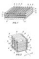
- Figure 1 shows a device 1 for producing a honeycomb core for a sandwich panel, consisting of a base plate 2 with a profile 3 and a plurality of press grids 4.
- Each grid 4 consists of a number of prismatic rods 5 made of an aluminum alloy, which are preferably have a hexagonal cross section.
- the top of the base plate 2 and the rods 5 are coated with a release agent.
- the individual bars 5 of a grid 4 are at a predetermined distance from one another and are arranged within a grid 4 in such a way that the bars 5 of a particular grid are offset from the bars 5 of the grids 4 which are adjacent downwards and upwards.
- a layer of fiber material (prepreg) impregnated with a curable plastic is first placed on the base plate 2. Then a press grid 4 is placed on the prepreg layer in such a way that its bars 5 run parallel to the profiling of the base plate. Now a prepreg layer 6, a grid 4, a prepreg layer 6, a grid 4, etc. are continuously placed on top of each other until the stack has reached the desired height. The stack is now pressed transversely to the bars 5. After curing in a suitable oven, the individual prepreg layers 6 form a coherent honeycomb structure, each prepreg layer 6 having a wave-shaped course and layers lying one above the other in the stack being bonded to one another in strip-shaped regions.
- the rods 5 are pulled out and the honeycomb block is in principle finished.
- a coating based on polytetrafluoroethylene (PTFE) is used as the release agent.
- PTFE polytetrafluoroethylene
- FIG. 2 shows schematically a device for producing a honeycomb core with vertical layering.
- the grids 4 are aligned vertically with the bars 5, so that the prepreg layers 6 can be introduced between the grids 4 from above.
- the rods 5 of a grid 4 are each connected on one side by a carrier 7, which is made of a tension element 8 running.
- the individual tension elements 8 are led out alternately to + y and - y.
- the grids 4 are in the positions shown within an upgrade station.
- the prepreg layers 6 coming from a roll are guided from above between the grids 4, which may be supported by grippers coming from below, which guide each end of the prepreg down and clamp it here, the upper end also being fixed after it has left the roll is separated. If all the prepreg layers 6 are cracked in, the grids 4 are brought closer to one another in the x direction in such a way that the prepreg layers 6 receive a wave shape and touch one another in strip-shaped areas. Then the stack thus formed is picked up by a pressing device which also serves as a transport pallet. The stack is hereby pressed as described above and then brought with it into a suitable oven for curing. A new stack can be put together in the upgrade station during curing.
- the stack arrives in a demolding station.
- the grids 4 are pulled out of the stack by means of the pulling elements 8.
- pull-out devices are provided which are brought into engagement with the tension elements 8.
- the rods 5 can also have any other suitable cross-sectional shape. All processes taking place in the devices described above can be carried out by means of controllable devices on the basis of customary automation measures. Both electrical, hydraulic and pneumatic actuations are possible.
- the selection of the materials used is based on professional considerations and affects both the honeycomb cores and the devices for their manufacture.
Landscapes
- Laminated Bodies (AREA)
- Casting Or Compression Moulding Of Plastics Or The Like (AREA)
- Moulding By Coating Moulds (AREA)
Abstract
Die Erfindung bezieht sich auf ein Verfahren zur Herstellung eines wabenförmigen Kernes aus einem mit einem aushärtbaren Kunststoff vorimprägnierten Fasermaterial für eine Leichtbau Verbundplatte und besteht im Ablauf folgender Verfahrensschritte:
- a. Abwechselndes Schichten einer Prepregschicht 6 und eines - Gitters 4, einer Prepregschicht 6, eines Gitters 4, einer Prepregschicht 6, eines Gitters 4 und so fort bis die vorbestimmte Dicke des Stapels erreicht ist, wobei die Gitter 4 durch parallele Stäbe 5 mit einem vorbestimmten Abstand gebildet sind und die Stäbe 5 eines Gitters 4 gegenüber den Stäben 5 eines benachbarten Gitters 4 auf Lücke versetzt - sind;
- b. Pressen des Stapels senkrecht zu den Achsen der Stäbe 5;
- c. Aushärten des Stapels unter Druck und Wärme sowie
- d. Herausziehen der Stäbe 5 aus dem Stapel.
- a. Alternately layering a prepreg layer 6 and a - grid 4, a prepreg layer 6, a grid 4, a prepreg layer 6, a grid 4 and so on until the predetermined thickness of the stack is reached, the grid 4 by parallel bars 5 at a predetermined distance are formed and the bars 5 of a grid 4 are offset from the bars 5 of an adjacent grid 4 - are;
- b. Pressing the stack perpendicular to the axes of the bars 5;
- c. Curing the stack under pressure and heat as well
- d. Pull the rods 5 out of the stack.
Das Verfahren kann sowohl mit horizontaler als auch mit vertikaler Schichtung durchgeführt werden. Insbesondere bei vertikaler Schichttung ist von Vorteil, daß alle hierbei ablaufenden Vorgänge mittels ansteuerbarer Einrichtungen weitgehend automatisch ausgeführt werden können. 
Description
Die Erfindung bezieht sich auf ein Verfahren nach dem Oberbegriff des Anspruchs 1.The invention relates to a method according to the preamble of claim 1.
Waben zum Aufbau von Leichtbau-Verbundplatten (Sandwichplatten) werden dadurch hergestellt, daß ein Stapel von nicht imprägnierten Papierbogen, die an vorbestimmten Stellen in streifenförmigen Bereichen miteinander verklebt sind, zu einem Wabenblock auseinandergereckt und dann als Block mit einem aushärtbaren Kunstharz imprägniert werden. Nach dem Aushärten des Kunstharzes wird ein derartiger Block senkrecht zur Erstreckung der Waben in beliebig dicke Scheiben geschnitten, die dann als Kerne für Sandwichplatten verwendet werden. Bei einer derartigen Platte ist der Wabenkern zwischen zwei in der Regel planparallel verlaufenden Deckschichten von hoher Zugfestigkeit angeordnet, wobei die Längserstreckung der Waben senkrecht zu den Deckschichten orientiert ist. Dieser Aufbau einer Sandwichplatte ergibt optimale Leichtbau-Eigenschaften.Honeycombs for the construction of lightweight composite panels (sandwich panels) are produced by stretching a stack of non-impregnated sheets of paper, which are bonded to one another at predetermined locations in strip-shaped areas, to form a honeycomb block and then impregnating them as a block with a hardenable synthetic resin. After the synthetic resin has hardened, such a block is cut perpendicularly to the extension of the honeycomb into slices of any thickness, which are then used as cores for sandwich panels. In the case of such a plate, the honeycomb core is arranged between two cover layers of high tensile strength, which are generally plane-parallel, the longitudinal extent of the honeycombs being oriented perpendicular to the cover layers. This structure of a sandwich panel results in optimal lightweight properties.
Bei der Herstellung der betreffenden Waben werden jedoch noch entscheidende Arbeitsgänge wie das Recken und Imprägnieren von Hand ausgeführt, was sich infolge des relativ hohen Lohnanteils ungünstig auf die Herstellkosten der Leichtbauplatten auswirkt. Als Imprägniermittel wird Phenolharz verwendet, das wegen seiner Toxizität bei der Verarbeitung sowie im Brandfalle problematisch ist. Die Freisetzung giftiger Rauchgase ist besonders bei der Verwendung der betreffenden Platten beim Bau von Passagierflugzeugen von Bedeutung.In the manufacture of the honeycomb in question, however, crucial operations such as stretching and impregnation are carried out by hand, which has an unfavorable effect on the manufacturing costs of the lightweight panels due to the relatively high proportion of wages. Phenolic resin is used as an impregnating agent, which is problematic due to its toxicity during processing and in the event of fire. The release of toxic fumes is particularly important when using the panels in question when building passenger aircraft.
Demgemäß leigt der Erfindung die Aufgabe zugrunde, ein gattungsgemäßes Verfahren derart anzugeben, daß dabei wesentliche Arbeitsgänge vollautomatisch ausgeführt werden können und das verwendete Material, insbesondere bei seiner Verarbeitung weniger giftige Gase entwickelt, wobei der vorbeschriebene Aufbau der Sandwichplatten im Prinzip unverändert bleibt.Accordingly, the invention has for its object to provide a generic method such that essential operations can be carried out fully automatically and the material used, especially when processing less toxic gases, the above structure of the sandwich panels remains in principle unchanged.
Diese Aufgabe ist bei einem gattungsgemäßen Verfahren durch die kennzeichnenden Merkmale des Patentanspruchs 1 gelöst. Vorteilhafte Weiterbildungen der Erfindung sind in den Unteransprüchen angegeben.This object is achieved in a generic method by the characterizing features of claim 1. Advantageous developments of the invention are specified in the subclaims.
Die Erfindung ist anhand der Zeichnung dargestellt und in der Beispielbeschreibung näher erläutert. Es zeigen
- Fig. 1 im Prinzip eine Vorrichtung zur Herstellung eines Wabenkerns für eine Sandwichplatte und
- Fig. 2 eine Vorrichtung mit vertikaler Schichtung.
- Fig. 1 in principle a device for producing a honeycomb core for a sandwich panel and
- Fig. 2 shows a device with vertical stratification.
Figur 1 zeigt eine Vorrichtung 1 zur Herstellung eines Wabenkerns für eine Sandwichplatte, bestehend aus einer Grundplatte 2 mit einer profilierung 3 und einer Vielzahl von Preßgittern 4. Jedes Gitter 4 besteht aus einer Anzahl von aus einer Aluminiumlegierung hergestellter prismatischer Stäbe 5, die vorzugsweise einen sechseckigen Querschnitt aufweisen. Die Oberseite der Grundplatte 2 sowie die Stäbe 5 sind mit einem Trennmittel beschichtet. Die einzelnen Stäbe 5 eines Gitters 4 weisen einen vorbestimmten Abstand voneinander auf und sind innerhalb eines Gitters 4 derart angeordnet, daß jeweils die Stäbe 5 eines bestimmten Gitters gegenüber den Stäben 5 der nach unten und nach oben benachbarten Gitter 4 auf Lücke versetzt sind.Figure 1 shows a device 1 for producing a honeycomb core for a sandwich panel, consisting of a
Zur Herstellung eines Wabenkerns wird zunächst eine Schicht aus mit einem aushärtbaren Kunststoff imprägniertem Fasermaterial (Prepreg), auf die Grundplatte 2 gelegt. Anschließend wird ein Preßgitter 4 derart auf die Prepregschicht gelegt, daß dessen Stäbe 5 parallel zu der Profilierung der Grundplatte verlaufen. Nun werden fortlaufend eine Prepregschicht 6, ein Gitter 4, eine Prepregschicht 6, ein Gitter 4 u.s.w. aufeinandergelegt, bis der Stapel die gewünschte Höhe erreicht hat. Der Stapel wird nun quer zu den Stäben 5 gepreßt. Nach dem Aushärten in einem geeigneten Ofen bilden die einzelnen Prepregschichten 6 eine zusammenhängende Wabenstruktur, wobei jede Prepregschicht 6 einen wellenförmigen Verlauf zeigt und jeweils im Stapel übereinander liegende Schichten in streifenförmigen Bereichen miteinander verklebt sind. Nach dem Abkühlen des Stapels werden die Stäbe 5 herausgezogen und der Wabenblock ist im Prinzip fertig. Als Trennmittel wird eine auf Polytetrafluoräthylen (PTFE) basierende Beschichtung verwendet. Insbesondere bei Verwendung von Prepregs, deren Fasern aus Graphit bestehen, hat sich überraschend gezeigt, daß das Herausziehen der Stäbe 5 keinerlei Schwierigkeiten bereitet.To produce a honeycomb core, a layer of fiber material (prepreg) impregnated with a curable plastic is first placed on the
Figur 2 zeigt schematisch eine Vorrichtung zur Herstellung eines Wabenkerns mit vertikaler Schichtung. Hier sind die Gitter 4 mit den Stäben 5 vertikal ausgerichtet, so daß die Prepregschichten 6 von oben zwischen die Gitter 4 eingeleitet werden können. Die Stäbe 5 eines Gitters 4 sind jeweils einseitig durch einen Träger 7 miteinander verbunden, der in ein Zugelement 8 aus läuft. Die einzelnen Zugelemente 8 sind abwechselnd nach + y und - y herausgeführt. Mit dieser Anordnung der Gitter 4, wie auch bei der horizontalen Schichtung nach Fig. 1, ist eine nahezu vollautomatische Herstellung von Wabenkernen durchführbar. Bei der Vorrichtung nach Fig. 2 ist beispielsweise folgendes Vorgehen denkbar. Innerhalb einer Aufrüststation befinden sich die Gitter 4 in den gezeigten Positionen. Hier werden die von einer Rolle kommenden Prepregschichten 6 von oben zwischen die Gitter 4 geführt, was möglicherweise durch von unten kommende Greifer unterstützt wird, die jedes Prepregende nach unten führen und hier festklemmen, wobei auch das obere Ende fixiert wird, nachdem es von der rolle abgetrennt ist. Sind alle Prepregschichten 6 eingebrackt, werden die Gitter 4 in x-Richtung einander derart genähert, daß die Prepregschichten 6 eine Wellenform erhalten und sich gegenseitig in streifenförmigen Bereichen berühren. Dann wird der so gebildete Stapel von einer Preßvorrichtung aufgenommen, die gleichzeitig als Transportpalette dient. Hiermit wird der Stapel wie vorbeschrieben gepreßt und dann mit dieser in einen geeigne- ten Ofen zum Aushärten gebracht. Während des Aushärtens kann in der Aufrüststation ein neuer Stapel zusammengestellt werden. Ist der Stapel ausgehärtet, gelangt er in eine Entformstation. Hier werden die Gitter 4 mittels der Zugelemente 8 aus dem Stapel herausgezogen. Hierzu sind Ausziehvorrichtungen vorgesehen, die mit den Zugelementen 8 in Eingriff gebracht werden. Anstelle des sechseckigen Querschnittes können die Stäbe 5 auch jede andere geeignete Querschnittsform aufweisen. Alle bei den vorbeschriebenen Vorrichtungen ablaufenden Vorgänge können aufgrund fachüblicher Maßnahmen der Automation mittels ansteuerbarer Einrichtungen ausgeführt werden. Dabei sind sowohl elektrische, hydraulische oder pneumatische Betätigungen möglich.Figure 2 shows schematically a device for producing a honeycomb core with vertical layering. Here, the
Auch hinsichtlich der Steuerung der Vorgänge sind alle geeigneten Prinzipien anwendbar, wobei insbesondere bei Verwendung di gitaler Steuersignale die Möglichkeit eröffnet wird, den Ablauf des aufgezeigten Verfahrens durch abgespeicherte Programme zu steuern.All suitable principles can also be used with regard to the control of the processes, with di gitaler control signals the possibility is opened to control the sequence of the shown method by stored programs.
Die Auswahl der verwendeten Werkstoffe erfolgt aufgrund fachüblicher Überlegungen und betrifft sowohl die Wabenkerne als auch die Vorrichtungen zu deren Herstellung.The selection of the materials used is based on professional considerations and affects both the honeycomb cores and the devices for their manufacture.
Claims (5)
Applications Claiming Priority (2)
| Application Number | Priority Date | Filing Date | Title |
|---|---|---|---|
| DE19873710416 DE3710416A1 (en) | 1987-03-28 | 1987-03-28 | METHOD FOR PRODUCING A HONEYCOMB-SHAPED CORE FOR A LIGHTWEIGHT COMPOSITE PLATE |
| DE3710416 | 1987-03-28 |
Publications (2)
| Publication Number | Publication Date |
|---|---|
| EP0284848A2 true EP0284848A2 (en) | 1988-10-05 |
| EP0284848A3 EP0284848A3 (en) | 1990-06-06 |
Family
ID=6324307
Family Applications (1)
| Application Number | Title | Priority Date | Filing Date |
|---|---|---|---|
| EP88103674A Withdrawn EP0284848A3 (en) | 1987-03-28 | 1988-03-09 | Process for making a honeycomb core for a sandwich panel |
Country Status (2)
| Country | Link |
|---|---|
| EP (1) | EP0284848A3 (en) |
| DE (1) | DE3710416A1 (en) |
Cited By (9)
| Publication number | Priority date | Publication date | Assignee | Title |
|---|---|---|---|---|
| EP0486615A4 (en) * | 1989-08-15 | 1992-08-05 | Foster-Miller Inc. | Film-based composite structures for ultralightweight sdi systems |
| DE4243919A1 (en) * | 1991-12-24 | 1993-07-01 | Ncr Gmbh | Data input and display device with LCD elements - has honeycomb writing surface with light-transmitting areas aligned with LCD elements |
| US5348601A (en) * | 1993-06-23 | 1994-09-20 | The United States Of America As Represented By The Secretary Of The Navy | Method of making an offset corrugated sandwich construction |
| US5399221A (en) * | 1990-05-04 | 1995-03-21 | Northrop Grumman Corporation | Continuous process for forming fiber-reinforced high temperature thermoplastic resin honeycomb structures |
| DE102006038666A1 (en) * | 2006-08-17 | 2008-02-28 | Airbus Deutschland Gmbh | Production method of workpiece made of fiber-composite material used in load bearing structure for aircraft, involves removing support and secondary material formed on upper surface of workpiece blank to form workpiece |
| US8821666B2 (en) | 2006-08-17 | 2014-09-02 | Airbus Operations Gmbh | Production method for a workpiece composed of a fibre-composite material, and a fibre-composite component in the form of a profile with a profile cross section which varies over its length |
| RU2623781C2 (en) * | 2015-11-11 | 2017-06-29 | Государственный научный центр Российской Федерации - федеральное государственное унитарное предприятие "Исследовательский Центр имени М.В. Келдыша" | Manufacturing method of celled honeycomb filler from composite materials |
| RU2673049C1 (en) * | 2018-02-08 | 2018-11-21 | Общество с ограниченной ответственностью "Научно-производственная компания "РБ-Композит" | Method for continuous hot forming a honeycomb filler from prepreg |
| CN115087248A (en) * | 2022-07-04 | 2022-09-20 | 南京克锐斯自动化科技有限公司 | High-precision automatic sequencing fixing system for production of laminated printed circuit board |
Families Citing this family (4)
| Publication number | Priority date | Publication date | Assignee | Title |
|---|---|---|---|---|
| DE3915249A1 (en) * | 1989-05-10 | 1991-01-24 | Dornier Gmbh | SANDWICH COMPONENT |
| DE3919615A1 (en) * | 1989-06-15 | 1990-12-20 | Peter Schmidt | Hollow structures formed of several layers of reinforced plastic - formed from rigid lightweight structures built using meltable cores which are removed after curing resin matrix |
| FR2657107A1 (en) * | 1990-01-15 | 1991-07-19 | Minnesota Rubber France | Dismantleable floor, particularly for painting installations |
| RU2770124C1 (en) * | 2021-04-20 | 2022-04-14 | Федеральное государственное бюджетное образовательное учреждение высшего образования "Сибирский государственный университет науки и технологий имени академика М.Ф. Решетнева" (СибГУ им. М.Ф. Решетнева) | Method for manufacturing a honeycomb filler from polymer composite materials |
Family Cites Families (9)
| Publication number | Priority date | Publication date | Assignee | Title |
|---|---|---|---|---|
| GB613529A (en) * | 1944-12-16 | 1948-11-30 | Libbey Owens Ford Glass Co | Improvements in light-weight compound sheet materials |
| US2790207A (en) * | 1952-11-10 | 1957-04-30 | Hexcel Products Inc | Method of expanding honeycomb |
| FR1318714A (en) * | 1962-01-09 | 1963-02-22 | Method and device for the production of honeycomb structures in laminated plastic material, and honeycomb structures obtained by means of this method and device | |
| US3356555A (en) * | 1964-10-29 | 1967-12-05 | Hexcel Corp | Method and apparatus for the manufacture of honeycomb product |
| DE2125463A1 (en) * | 1971-05-22 | 1972-12-14 | Ferndorf Eisen Metall | Plastic insulation panels - with honeycombed fibre glass reinforcing esp for boat and general construction |
| FR2486874A1 (en) * | 1979-07-19 | 1982-01-22 | United Kingdom Government | IMPROVED HONEYCOMB STRUCTURE AND MANUFACTURING METHOD |
| CA1166942A (en) * | 1980-02-09 | 1984-05-08 | Martin P. Ansell | Cellular composites and process and apparatus for their manufacture |
| FR2480741A1 (en) * | 1980-04-18 | 1981-10-23 | Aerospatiale | POROUS LAYER FOR COMPOSITE STRUCTURE FOR ABSORPTION OF SOUND ENERGY AND METHOD OF MANUFACTURING THE SAME |
| WO1987006186A1 (en) * | 1986-04-11 | 1987-10-22 | H R Smith (Technical Developments) Limited | Lightweight high temperature thermoplastics material structures |
-
1987
- 1987-03-28 DE DE19873710416 patent/DE3710416A1/en not_active Withdrawn
-
1988
- 1988-03-09 EP EP88103674A patent/EP0284848A3/en not_active Withdrawn
Cited By (14)
| Publication number | Priority date | Publication date | Assignee | Title |
|---|---|---|---|---|
| EP0486615A4 (en) * | 1989-08-15 | 1992-08-05 | Foster-Miller Inc. | Film-based composite structures for ultralightweight sdi systems |
| US5443884A (en) * | 1989-08-15 | 1995-08-22 | Foster-Miller, Inc. | Film-based composite structures for ultralightweight SDI systems |
| US5399221A (en) * | 1990-05-04 | 1995-03-21 | Northrop Grumman Corporation | Continuous process for forming fiber-reinforced high temperature thermoplastic resin honeycomb structures |
| DE4243919A1 (en) * | 1991-12-24 | 1993-07-01 | Ncr Gmbh | Data input and display device with LCD elements - has honeycomb writing surface with light-transmitting areas aligned with LCD elements |
| US5565892A (en) * | 1991-12-24 | 1996-10-15 | Ncr Corporation | Display and data entry device and method for manufacturing the same |
| US5348601A (en) * | 1993-06-23 | 1994-09-20 | The United States Of America As Represented By The Secretary Of The Navy | Method of making an offset corrugated sandwich construction |
| DE102006038666A1 (en) * | 2006-08-17 | 2008-02-28 | Airbus Deutschland Gmbh | Production method of workpiece made of fiber-composite material used in load bearing structure for aircraft, involves removing support and secondary material formed on upper surface of workpiece blank to form workpiece |
| DE102006038666B4 (en) * | 2006-08-17 | 2009-09-24 | Airbus Deutschland Gmbh | Manufacturing method for a workpiece made of a fiber composite material and apparatus for producing a workpiece made of a fiber composite material |
| US8821666B2 (en) | 2006-08-17 | 2014-09-02 | Airbus Operations Gmbh | Production method for a workpiece composed of a fibre-composite material, and a fibre-composite component in the form of a profile with a profile cross section which varies over its length |
| US8920698B2 (en) | 2006-08-17 | 2014-12-30 | Airbus Operations Gmbh | Production method for a workpiece composed of a fibre-composite material |
| RU2623781C2 (en) * | 2015-11-11 | 2017-06-29 | Государственный научный центр Российской Федерации - федеральное государственное унитарное предприятие "Исследовательский Центр имени М.В. Келдыша" | Manufacturing method of celled honeycomb filler from composite materials |
| RU2673049C1 (en) * | 2018-02-08 | 2018-11-21 | Общество с ограниченной ответственностью "Научно-производственная компания "РБ-Композит" | Method for continuous hot forming a honeycomb filler from prepreg |
| CN115087248A (en) * | 2022-07-04 | 2022-09-20 | 南京克锐斯自动化科技有限公司 | High-precision automatic sequencing fixing system for production of laminated printed circuit board |
| CN115087248B (en) * | 2022-07-04 | 2023-08-04 | 南京克锐斯自动化科技有限公司 | High-precision automatic sequencing and fixing system for production of laminated printed circuit board |
Also Published As
| Publication number | Publication date |
|---|---|
| EP0284848A3 (en) | 1990-06-06 |
| DE3710416A1 (en) | 1988-10-13 |
Similar Documents
| Publication | Publication Date | Title |
|---|---|---|
| DE69212489T2 (en) | Process and object for the production of mats | |
| DE2932201C2 (en) | ||
| EP2715835B1 (en) | Energy storage module comprising a plurality of, in particular, prismatic storage cells, and method for producing an energy storage module, and also method for producing an end plate for an energy storage module | |
| EP2046564B1 (en) | Method for production of several fibre composite components | |
| DE69022566T2 (en) | PUNCHABLE SHEET OF FIBER REINFORCED THERMOPLASTIC PLASTIC AND MOLDED PRODUCT THEREOF. | |
| DE102012022713B3 (en) | Panel and method of making a panel | |
| DE3710416A1 (en) | METHOD FOR PRODUCING A HONEYCOMB-SHAPED CORE FOR A LIGHTWEIGHT COMPOSITE PLATE | |
| CH637570A5 (en) | HOT DEFORMABLE PLASTIC COMPOSITE PLATE AND METHOD FOR HOT FORMING AND PRODUCING THE PLATE. | |
| DE2322371B2 (en) | A method for continuously producing a molded article from foamed fiber-reinforced synthetic resin and an apparatus for carrying out the method | |
| DE3200877C2 (en) | Method and device for manufacturing leaf springs from fiber-reinforced materials | |
| DE19941300A1 (en) | Heat-formable press board | |
| DE69003088T2 (en) | Textile core, process for the production thereof of composite goods obtained with such a textile core. | |
| DE3127505C2 (en) | Process for producing a laminate | |
| DE102010004865A1 (en) | System for continuously producing sandwich composite structure, has honeycomb core that is arranged between two cover layers, where cover layers formed by extruded fiber-reinforced plastic components | |
| EP0152837B1 (en) | Method and apparatus for making fibre sheets for use as preforms for pressed articles | |
| DE102006038666B4 (en) | Manufacturing method for a workpiece made of a fiber composite material and apparatus for producing a workpiece made of a fiber composite material | |
| WO2022253612A1 (en) | Prepreg stack and method for producing same | |
| DE102007004314B4 (en) | Method for producing a fiber composite component with at least one interspersed region for an aircraft or spacecraft | |
| DE102018115121B4 (en) | Method for producing a resin composite panel and method for producing a three-dimensional object | |
| EP2703150A1 (en) | Method and device for inserting layers of rovings into a press | |
| DE102011002906B4 (en) | Forming core and process for draping unidirectional 0 ° fiber layers | |
| DE69500716T2 (en) | Method and machine for producing a block-shaped reinforcement for a part made of composite material | |
| DE69503786T2 (en) | METHOD AND DEVICE FOR PRODUCING A THREE-DIMENSIONAL FIBER-REINFORCED OBJECT | |
| DE2316860A1 (en) | PROCESS FOR MANUFACTURING THREE-DIMENSIONAL REINFORCED INSULATION BLOCKS | |
| DE19818406C1 (en) | Making panels of corrugated sheet composite based on unwoven fiberglass substrate material |
Legal Events
| Date | Code | Title | Description |
|---|---|---|---|
| PUAI | Public reference made under article 153(3) epc to a published international application that has entered the european phase |
Free format text: ORIGINAL CODE: 0009012 |
|
| AK | Designated contracting states |
Kind code of ref document: A2 Designated state(s): BE FR GB LU |
|
| PUAL | Search report despatched |
Free format text: ORIGINAL CODE: 0009013 |
|
| AK | Designated contracting states |
Kind code of ref document: A3 Designated state(s): BE FR GB LU |
|
| STAA | Information on the status of an ep patent application or granted ep patent |
Free format text: STATUS: THE APPLICATION IS DEEMED TO BE WITHDRAWN |
|
| 18D | Application deemed to be withdrawn |
Effective date: 19900401 |