EP0284857A2 - Ramasseuse-enrouleuse pour récolte - Google Patents
Ramasseuse-enrouleuse pour récolte Download PDFInfo
- Publication number
- EP0284857A2 EP0284857A2 EP88103831A EP88103831A EP0284857A2 EP 0284857 A2 EP0284857 A2 EP 0284857A2 EP 88103831 A EP88103831 A EP 88103831A EP 88103831 A EP88103831 A EP 88103831A EP 0284857 A2 EP0284857 A2 EP 0284857A2
- Authority
- EP
- European Patent Office
- Prior art keywords
- winding
- partition element
- chamber
- gate
- roll
- Prior art date
- Legal status (The legal status is an assumption and is not a legal conclusion. Google has not performed a legal analysis and makes no representation as to the accuracy of the status listed.)
- Granted
Links
- 238000005192 partition Methods 0.000 claims abstract description 106
- 238000012432 intermediate storage Methods 0.000 claims abstract description 8
- 239000000463 material Substances 0.000 claims abstract description 6
- 238000004804 winding Methods 0.000 claims description 97
- 239000011230 binding agent Substances 0.000 claims description 64
- 238000003825 pressing Methods 0.000 claims description 11
- 238000003780 insertion Methods 0.000 claims description 9
- 230000037431 insertion Effects 0.000 claims description 9
- 230000005484 gravity Effects 0.000 claims description 5
- 238000010348 incorporation Methods 0.000 claims description 3
- 230000010354 integration Effects 0.000 claims description 2
- 239000011888 foil Substances 0.000 claims 1
- 239000002184 metal Substances 0.000 claims 1
- 239000004753 textile Substances 0.000 claims 1
- 238000010276 construction Methods 0.000 abstract description 2
- 238000003860 storage Methods 0.000 abstract 1
- 238000013461 design Methods 0.000 description 7
- 238000000034 method Methods 0.000 description 7
- 230000002349 favourable effect Effects 0.000 description 5
- 229910000831 Steel Inorganic materials 0.000 description 2
- 230000015572 biosynthetic process Effects 0.000 description 2
- 238000005056 compaction Methods 0.000 description 2
- 238000005096 rolling process Methods 0.000 description 2
- 239000010959 steel Substances 0.000 description 2
- 239000004677 Nylon Substances 0.000 description 1
- 238000013459 approach Methods 0.000 description 1
- 239000011248 coating agent Substances 0.000 description 1
- 238000000576 coating method Methods 0.000 description 1
- 239000004744 fabric Substances 0.000 description 1
- 238000004519 manufacturing process Methods 0.000 description 1
- 229920001778 nylon Polymers 0.000 description 1
- 230000002093 peripheral effect Effects 0.000 description 1
- 239000006223 plastic coating Substances 0.000 description 1
- 238000000926 separation method Methods 0.000 description 1
- 238000012546 transfer Methods 0.000 description 1
- 230000007704 transition Effects 0.000 description 1
Images


Classifications
-
- A—HUMAN NECESSITIES
- A01—AGRICULTURE; FORESTRY; ANIMAL HUSBANDRY; HUNTING; TRAPPING; FISHING
- A01F—PROCESSING OF HARVESTED PRODUCE; HAY OR STRAW PRESSES; DEVICES FOR STORING AGRICULTURAL OR HORTICULTURAL PRODUCE
- A01F15/00—Baling presses for straw, hay or the like
- A01F15/07—Rotobalers, i.e. machines for forming cylindrical bales by winding and pressing
- A01F15/0705—Arrangements for continuous operation
Definitions
- the invention relates to a roller baler of the type specified in the preamble of claim 1.
- a roller baler of this type known from DE-PS 33 11 330 is equipped in the feed channel for the crop with a prechamber which forms the intermediate store for the crop that continues to be supplied during the incorporation and ejection of the finished roller bale.
- movable elements are provided in the feed channel, which interrupt the feeding of crop to the winding chamber, so that the picked crop is stored in the buffer. Since up to half of the crop contained in the next roll bale is fed in during the binding and ejection of the finished roll bale, the antechamber must be dimensioned large. This inappropriately enlarges the housing of the roller baler.
- the movement control required for the elements which interrupt the supply of the crop to the winding chamber during the binding and ejection phase is also unfavorable.
- such a roller baler is almost twice as expensive as a conventional roller baler that can be used in discontinuous operation, which is hardly portable for the end user.
- roller baler of a different type known from EP-A 1-01 56 041
- two wrapping chambers are provided in one housing, a small roller bale being formed in the first wrapping chamber and then in the second
- the wrapping chamber is transferred and wrapped to the end, while a new roll bale is started in the first wrapping chamber.
- This roller baler is extremely large and complicated, making it prone to failure and expensive.
- the invention has for its object to provide a roller baler of the type mentioned, which is characterized by a simple and trouble-free and compact structure.
- roller baler This design results in a structure of the roller baler that is as simple and compact as that of a discontinuously movable roller baler.
- the roll baler can be operated continuously because the harvested crop is collected separately from the finished roll bale during the binding and ejection in the buffer .
- the flexible partition element adapts to the contour of the finished roll bale, compresses the crop that continues to be supplied and holds it in the winding chamber when the finished and bound roll bale is ejected, where it is immediately further processed.
- the roller baler hardly differs from an only discontinuously movable roller baler. The production is simple and inexpensive, so that the cost of this Increase continuously movable roll baler barely noticeably compared to the costs of a discontinuously movable roll baler.
- the features of claim 4 are expedient because the partition element prevents the supplied crop from reaching the finished roll bale in this embodiment.
- the catch element not only simplifies gripping the insertion end of the partition element, but also forms a driver with which the partition element is brought up to the catching and holding device practically without slippage.
- the embodiment of claim 5 is also favorable because these materials of the partition element ensure that the partition element forms an enlarging loop in the winding chamber, which delimits the intermediate storage.
- the partition wall element is flexible and deformable, but is also tensile and easy to slide, so that it can be used with little wear.
- This partition wall element is particularly wear-resistant and therefore well suited to the rough conditions in the roller baler.
- the embodiment according to claim 7 is also advantageous.
- the outlay in terms of apparatus for controlling the movement of the partition element is thereby kept low and simple.
- the partition element is held wound on the housing like a spring roller blind, is passed with the introducer to the roller bale, unwound from it and - while the roller bale is being ejected - pulled back and tensioned, which has the advantage that the partition element on the roller bale exerts a force in the direction of ejection exercises, which speeds up the ejection.
- the measure of claim 8 can also be expedient.
- the trigger brake can produce a desired slippage between the partition element and the finished roll bale, which supports the ejection of the roll bale and pre-compresses the supplied crop in a desirable manner.
- the feature of claim 9 is also useful because the return spring automatically ensures that the Partition element is withdrawn during the ejection movement of the finished roll bale and tensioned in the process.
- the feature of claim 10 is also expedient because the crossbar can be easily gripped by the catching and holding device and because the crossbar also ensures that the partition element follows the rotary movement of the roll bale evenly over its entire width.
- a structurally simple and reliable embodiment is further evident from claim 11.
- the catch hook is then inserted into the winding chamber when the insertion of the partition element approaches the catching and holding device.
- claim 12 is also important, because in this way it is ensured that the binding agent can be closed in the joint region of its ends, or that there is a relatively wide overlap region of the binding agent ends, which ensures that the binding agent is firmly seated on the finished roll bale important is.
- the idea of claim 14 is also important.
- the catching and holding device is expediently arranged in the winding direction only so far after the mouth of the feed channel that there is a sufficient size for the intermediate store if that Introducer of the partition element is caught and forms a loop, which should not, however, reach the feed opening for the binder.
- the dividing wall element only has to be moved over a small part of the inner circumference of the wrapping chamber, because when the binder is applied, the harvested crop is introduced into the finished roll bale. Only when the front end of the binding agent comes into the vicinity of the feed channel is the partition wall element also introduced, which then runs past the mouth of the feed channel and separately picks up the crop that continues to be supplied from the roll bale that is then produced.
- the roller bale is, so to speak, almost completely driven into the partition element, except for a short gap between the catching device and the feed area of the partition element, in which the ends of the binding agent can be connected or overlapped.
- the mouth of the feed channel is covered by the partition element only for a short period of time, so that only a small amount of crop has to be conveyed and collected in the intermediate store.
- the crop that was fed in had been placed under the binding agent almost over the entire rotation of the roll bale.
- the finished roll bale is quickly conveyed out of the wrapping chamber when the gate opens, the re-conveyed crop pressing against the outside of the partition wall element supporting the ejection.
- the embodiment of claim 18 is also expedient because the feeders ensure a precisely timed feeding of the binder and the partition wall element at the beginning of the integration and ejection process.
- This design of the gate of the roller baler is also useful for other roller balers, for example for discontinuous driving, namely in In view of the fact that the roll bale emerging from the wrapping chamber is directed to the bottom on the inclined plane of the lower half of the door, or when the lower half is pivoted downwards over an inclined plane, it is forced to leave the wrapping chamber quickly, the in the Press elements provided in the lower half of the door support the ejection process.
- the upper half of the gate is lighter and easier to move than a one-piece gate that crosses the entire discharge opening and is hinged at the top, so that the motion drives can be designed more easily for both halves of the gate.
- the two-part door design has the advantage that with increasing filling of the intermediate storage there is the possibility of enlarging the winding chamber by gradually opening both halves of the door as it is corresponds to the increasing reaction pressure of the crop, and a force impulse is exerted on the finished roll bale with the partition element, which supports the ejection.
- the embodiment of claim 20 is expedient because the pressing element fixed to the housing forms a transition, so to speak, to the lower half of the gate forming the guide surface to the floor, this pressing element fixed to the housing accelerating the ejection process of the roller bale with its movement towards the lower half of the door.
- FIG. 21 out Another expedient embodiment is based Claim 21 out.
- These closing drives have the advantage that the door halves begin to open when a predetermined degree of compaction is reached in the roller bale, which can be determined by the reaction pressure on the door halves, and in which the door halves begin to open automatically, but initially at the same time Closing presses.
- This design is particularly expedient when using a partition element which forms the intermediate store in the winding chamber. With increasing filling of the intermediate store, namely the door halves are successively pressed open, which results in an increase in the capacity of the winding chamber, which is expedient especially for receiving the supplied crop in the intermediate store.
- the embodiment of claim 22 is favorable because, in this position of the catching and holding device, the partition element withdrawn and tensioned when ejected exerts an additional ejection impulse on the finished roll bale.
- the measure of claim 26 is favorable, because in this way a large intermediate store can be created which has no pronounced loop shape of the partition element, because the binding of the finished roll bale into the binder is completed immediately after the point in time at which the partition element is introduced the catching and holding device is reached on the last individual element, so that the finished roll bale can then be ejected immediately. Furthermore, the effective lever arm of the tensioned partition element on the ejection movement of the roll bale is favorable in this embodiment.
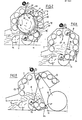
- roller balers 1, 1 ⁇ , 1 ⁇ , 1 ′′′, 1 IV and 1 V shown in the figures are roller balers with an essentially fixed winding or baling chamber 7, ie a wrapping or baling chamber, the size of which does not change when the roller baler is working.
- the principle explained below, of forming a buffer store Z directly and only temporarily within the wrapping chamber 7, can, however, also be used in roller balers with a variable wrapping or baling chamber.
- this principle is only explained with reference to the roller balers with a fixed wrapping or baling chamber, because it is difficult to draw in the case of roller balers with a variable wrapping or baling chamber.
- the roll baler 1 consists of a housing 3 which can be moved on wheels 2 and has a drawbar 4.
- the roll baler 1 is usually pulled and also driven by a tractor.
- Below the drawbar 4 runs an inclined upward feed channel 5 for the crop 6 into the inside of an approximately cylindrical winding chamber 7.
- a gate 8 Opposite the feed channel 5 there is an ejection opening which can be closed by a gate 8, which consists of an upper gate half 9 and a lower one Half of goal 11 exists.
- the upper gate half 9 can be swiveled up in the upper part of the housing 4 about a transverse axis 10, while the lower gate half 11 can be pivoted downward about a transverse axis 12 near the mouth of the feed channel 5.
- the winding chamber 7 is delimited by winding rollers 13 which are distributed in the circumferential direction with narrow spacings (somewhat more than 1 cm) and which can be driven to rotate in the direction of the arrows.
- the drive elements and the drives are located on the 1 housing sides not shown in Fig. 1 outside the winding chamber.
- the winding rollers 13 expediently have a corrugated surface. They are all driven in the same direction of rotation, so that there is a winding direction which runs from the gate 8 over the upper part of the winding chamber 7 downward only the mouth of the feed channel 5.
- a crop take-up and feed device 14 Arranged in the feed channel 5 is a crop take-up and feed device 14 which is driven continuously and continuously conveys the crop 6 into the winding chamber 7. For this reason, the roller baler 1 can be operated in continuous operation.
- closing drive devices 15 for the gate 8 which in the embodiment shown have a double-acting hydraulic cylinder 16 for the upper gate half 9 and a double-acting hydraulic cylinder 17 for the lower gate half 11, which are supported on the housing.
- each door half 9, 11 can be swung open and closed and held in the closed position with a preset closing force.
- hydraulic lines 18 and 19 are provided to the two ends of each cylinder, for example the hydraulic cylinder 16, an adjustable pressure relief valve 20 being provided in the hydraulic line 19 for closing the gate half 9, which pressure valve 20 is bypassed by a check valve 21.
- the check valve 21 can be unlocked so that the gate half 9 can also be opened quickly by acting on the hydraulic line 18.
- the pressure relief valve 20 limits the pressure in such a way that the gate half 9 begins to yield at a certain pressure in the winding chamber 7 and maintains its counter pressure until, for example, the check valve 21 is unlocked and the gate half 9 can be easily swung up.
- the same drive principle is provided for the lower half 11 of the door. In both door halves 9, 11 winding rollers 13 are included.
- a core 22 is rotatably mounted on the housing 3, on which a web-shaped partition element T is wound.
- a rotary drive 23 is connected to the core 22.
- a retraction spring 24 can be provided, which acts on the wound-up partition element T like a spring roller blind in the rewinding direction.
- the partition element T e.g. a coating web 25, i.e. can be a nylon fabric with plastic coating on both sides (see also FIGS. 5 and 6), has the width of the winding chamber 7 and an introducer 26 to which a catch element 27 is fastened.
- a roller 28 In the winding direction in front of the core 22, a roller 28 is rotatably mounted on the housing on which a binder 42, e.g. a network path is stored.
- the roller 28 is connected to a rotary drive 29 with which the binding agent 42 can be introduced into the winding chamber 7.
- a separating device 30 is provided in order to separate the binding agent each time a predetermined length has been unwound.
- roller 28 instead of the roller 28 with the associated components, another binder supply and supply device can also be provided there.
- a device with which the ends of the binder are connected in the usual way on the finished roll bale is also provided there.
- the partition element T and the binder 42 are the winding chamber 7 through a feed opening 31 between the fed to the top two winding rollers 13, which have moved somewhat away from each other.
- the feed opening 31 is shown enlarged.
- the door halves 9 and 11 delimit a closing joint 32 which lies somewhat below the horizontal plane in which the central axis of the winding chamber 7 is located.
- a catching and holding device 33 for the catching element 27 of the partition element T is provided on the lower half of the door 11. This has, for example, pivotable and displaceable catch hooks 34 and an actuating cylinder 35.
- the catch hook 34 can be inserted into the winding chamber 7 in the region of the closing joint 32.
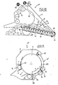
- the formation of the insertion end 26 of the partition element T can be seen in FIG. 5.
- the catching element 27 is a cross bar which is hammered into the web 25 of the partition element T and extends essentially over the entire width of the web. Recesses 28 in the web 25 make it easier for the provided catch hook 34 of the holding and catching device 33 to grip the insertion end 26.
- Fig. 6 indicates another design of the catching and holding device 33 ⁇ .
- the cross bar 27 in the introducer 26 of the partition element T is provided with a telescopically extendable pin 36 at each end, which is pressed outwards by a spring 37.
- the pins 36 slide along a housing wall 38 of the housing 3 until they enter recesses 39 in the housing wall 38 and are caught.
- a pressure stamp 40 in front of the recess 39 is by means of a Cylinder 41 can be actuated so that it pushes the pin 36 back into the recess 39, so that the introducer 26 or the web 25 of the partition element T can be moved again from the holding or catching position.
- roller baler 1 the function of the roller baler 1 is explained below.
- the winding chamber 7 is empty according to FIG. 1.
- the crop 6 is conveyed through the feed channel 5 into the winding chamber 7.
- Gate 8 is closed.
- the door halves 9 and 11 are kept closed with a set closing pressure.
- the catch hook 34 is withdrawn.
- the feeder 31 of the partition element and the free end of the binder 42 hang in the feed opening 31.
- the continuously supplied crop 6 gradually fills the winding chamber 7, circulating in the winding direction.
- the winding chamber 7 fills up gradually, the crop 6 being compressed.
- the winding rollers 13 run.
- the crop 6 is increasingly compacted, so that an even looser roll bale forms, to which the crop that is still fed is placed on the outside in the form of a spiral layer.
- the pressure against the gate 8 increases with increasing compaction of the roll bale formed in this way.
- a pressure sensor not shown, determines the point in time at which a sufficiently sealed roll bale is present. Then the introducer 26 of the partition element T and optionally the leading end of the binder are let in through the feed opening 31 under the influence of gravity. If necessary, the binder 42 runs in with a lead. The rotating roller bale takes the binding agent 42 and the partition element T with it until the catching element 27 passes the mouth of the feed channel 5 and in the vicinity of the Closing joint 32 arrives. The partition element T and also the binder 42 unwind independently.
- the catch hooks 34 are moved into the winding chamber 7, so that they grip the catch element 27 and prevent the further movement of the insertion end 26 of the partition wall element T with the roller bale (see FIG. 2). Since the roll bale R continues to take the partition element T with it, a loop S (FIG. 2) is formed between the outer circumference of the roll bale R and the winding rollers 13 of the upper gate half 9, the tip E of which is at half the speed of the orbital movement of the roll bale in the direction of Feed opening 31 moves along. As soon as the catch element 27 has passed the mouth of the feed channel 5, the crop 6 which is still supplied is no longer brought to the roll bale R, but is separated from the roll bale by the partition wall element T.
- the dividing wall element T forms in its loop S an intermediate storage Z for the crop that continues to be fed. Since the pressure on the door halves 9 and 11 increases during this movement phase, these slowly begin their opening movement while maintaining a closing force, so that the winding chamber 7 increases somewhat. The opening closing joint 32 between the door halves 9 and 11 still allows no crop to emerge because it is closed by the partition element T.
- the free end of the binder 42 As soon as, during this movement, the free end of the binder 42, designated 43, arrives in the region of the feed opening 31, or shortly before, the binder is cut off by means of the separating device 30 and the ends of the binder 42 are connected to one another in the usual manner, optionally in an overlap region 44.
- an externally mounted, adjustable pressure relief valve could also be provided, which allows the required closing pressure to be set as a function of the quality of the harvested crop.
- the roller baler 1 ⁇ shown in FIG. 7 differs from that previously described in that the winding or pressing elements 13 ⁇ are conveyor belt-like units which limit the winding chamber 7. Each unit has two spaced, parallel rollers 45 on which one or more belts or belts run. The cross section of the wrapping chamber is thereby polygonal, however, due to the contact pressure of the roll bale being formed, the belts 46 then bend, so that an approximately cylindrical winding chamber shape is nevertheless achieved and a cylindrical roll bale is formed.
- the roller baler 1 ⁇ contains as winding or pressing elements 13 ⁇ , in turn, conveyor belt-like units with drive rollers 47 and rod or link belts 48, which are additionally guided in curved form in guide links 49.
- the further structure and function of this roller baler 1 ⁇ corresponds to that of FIG. 1.
- the roll baler 1 ′′′ according to FIGS. 9 and 10 has around the circumference of the winding chamber 7 distributed closely adjacent winding rollers 13.
- the gate 8 ⁇ of the winding chamber 7 for ejecting the roll bale R is in one piece and by one underlying pivot axis adjacent to the mouth of the feed channel 5 pivotable.
- Each individual section 50 has an outer stop surface 52 and an inner one Stop surface 53.
- the winding rollers 13 are mounted on the hinge axes 51 between the individual sections.
- the individual sections 50 which abut one another with their abutment surfaces 53, form a door shell 54 with the radius of curvature of the winding chamber 7.
- a tension member 57 for example a chain or a steel cable, runs between the individual sections 50 each side, which is anchored in the housing to an abutment 58 and can be wound onto a drum 56 fixed to the housing.
- the tension element 57 is pulled, the shape of the door shell 54 is maintained even under the internal pressure of the roller bale R.
- the catch and holding device 33 for the catch element 27 of the partition element T is arranged on the last individual section 50, so that the catch hooks 34 can be inserted into the feed opening 31.
- the roller bale R has already been completed.
- the free end of the binder 42 has already reached the area of the feed opening 31 and is being connected to the other end of the binder 42.
- the partition element T wraps around the integrated roll bale R. Its catch element 27 is already gripped by the catch hooks 34.
- the buffer store Z is filled with crop 6 that is still supplied.
- the door shell 54 has opened somewhat, yielding the tension member 57.
- an adjustable slip clutch could be provided for the roller 56.
- the roller 56 like the core 22 of the partition element T, could be driven by a hydraulic motor which, when pulled on the tension member 57 or on the partition element, works like a pump against an adjustable pressure relief valve.
- a stretching drive 59 is provided between the individual sections 50 and is formed, for example, by side chains or steel cables and a tensioning device 60.
- the individual sections 50 are pivoted relative to one another until they abut against one another with the abutment surfaces 52 and in this way form a flat and rigid drain plate 61, the surface of which is formed by the winding rollers 13.
- the drain plate 61 is inclined to the floor. Since, at the same time, the dividing wall element is withdrawn and tensioned as mentioned with reference to FIG. 1, the finished roll bale runs on the unwinding plate 61 to the floor, the tension in the dividing wall element T supporting this rolling out movement.
- the roller baler 1 IV shown in FIG. 11 differs from that shown in FIG. 1 in that the gate 8 ⁇ is integral and rigid and can be pivoted away about an overhead pivot axis 62 on the housing.
- a hydraulic cylinder, not shown, similar to the hydraulic cylinder 16 of FIG. 1 controls the Gate movement.
- the gate 8 ⁇ has a rigid shell 63, in which 13 are mounted like winding rollers.
- the feed opening 31 for the binder 42 is located in the lower part of the gate 8 ⁇ .
- the catching and holding device 33 with the catch hook 34 is arranged in the housing 3 in front of the lower edge of the door shell 63. It has a distance D from the feed opening 31 in radians.
- the dividing wall element T is introduced into the winding chamber 7 in the winding direction before the mouth of the feed channel 5, for example through a feed opening 64.
- the dashed lines indicate that the partition element T could also be supplied only immediately before the mouth of the feed channel 5, and that the catch hooks 34 could also be arranged directly behind the mouth of the feed channel 5 in the winding direction.
- This design has the advantage that only a relatively small partition element length is used and only a small amount of crop is temporarily stored, because the partition element T only needs to form the buffer over the part of the rotational movement of the roller bale that the free end of the binder between the feed opening 64 and the feed opening 31 passes through. If the loop of the partition wall element T with the loop tip that forms after the catch element is caught by the catch hooks 34 extends to the feed opening 31, there is an overlap area for the binder 42 which corresponds to twice the value of the distance D. The binding process of the roll bale is already more than half complete when the front end of the binding agent reaches the feed opening 64, so that only a relatively short period of time passes until the roll bale is completely bound and can be ejected.
- the buffer store only needs a small amount of the crop that continues to be fed to record.
- the force pulse generated by the tensioning of the partition element during ejection supports the ejection of the fully integrated roll bale from the wrapping chamber 7.
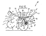
- the roller baler 1 V differs from the previous one in that the roller 28 for the binder 42 is mounted in the housing 3 near the closing joint of the gate 8 ⁇ , and that a feeder 65 for the binder 42 is provided there, which is the free end of the binder each against the circumferential surface of the roller bale, further by the catch hook 34 of the catching and holding device which can be pivoted on the axis of the winding roller 13 lying in the winding direction behind the mouth of the feed channel 5, and finally by the core 22 mounted in the lower end of the door shell 63 with the Partition wall element T.
- a feeder 66 is also assigned to the partition wall element T, with which the catch element 27 of the partition wall element T is applied to the peripheral surface of the roll bale.
- the binding agent 42 is introduced into the wrapping chamber 7 by means of the feeder 65 and taken away by the roll bale R. If the free end 43 of the Binder 42 has passed the area of the supply of the partition element T, the partition 66 is also introduced with the feeder 66 with the catch element 27 and taken away.
- the roller bale R rotates with the binding agent 42 and the dividing wall element T for almost one revolution, during which the crop that is still supplied is introduced under the binding agent. Only when the catch element 27 passes the mouth of the feed channel is the further supply of the crop material under the binding agent interrupted and the crop material temporarily stored on the outside of the partition wall element T.
- the catch element 27 After passing through the mouth of the feed channel 5, the catch element 27 is gripped and held by the catch hooks 34, so that the ends of the binding agent 42 can be connected to one another.
- a separation device for the binder is again indicated. It is formed, if at all, only a small buffer with a small loop, since the crop is only fed in over a short period of time.
- the gate 8 ⁇ can already start to open slowly and with counter pressure, so that the crop that is still being fed is not inappropriately compressed or jammed in the feed channel.
- the gate 8 das swings up quickly.
- the discharge opening for the roller bale is released. Since the catch element 27 still hangs in the catch hook 34 and the partition element T is tensioned or withdrawn, the finished roll bale is ejected. How quickly the roller bale is ejected is of no particular importance, since the tensioned partition element leaves a large space for the crop to be fed in easily.
- the gate becomes 8 ⁇ again closed, previously or in the process the partition element T is wound up and finally the catch element 27 is released until the catch element 27 has returned to the position shown in FIG. 12.
Landscapes
- Life Sciences & Earth Sciences (AREA)
- Environmental Sciences (AREA)
- Storage Of Harvested Produce (AREA)
- Basic Packing Technique (AREA)
- Auxiliary Devices For And Details Of Packaging Control (AREA)
- Press Drives And Press Lines (AREA)
- Spinning Or Twisting Of Yarns (AREA)
- Drying Of Solid Materials (AREA)
- Fertilizing (AREA)
- Preliminary Treatment Of Fibers (AREA)
- Containers And Plastic Fillers For Packaging (AREA)
- Pharmaceuticals Containing Other Organic And Inorganic Compounds (AREA)
- Wrapping Of Specific Fragile Articles (AREA)
- Harvesting Machines For Specific Crops (AREA)
Priority Applications (1)
| Application Number | Priority Date | Filing Date | Title |
|---|---|---|---|
| AT88103831T ATE69537T1 (de) | 1987-03-30 | 1988-03-10 | Rollballenpresse fuer erntegut. |
Applications Claiming Priority (2)
| Application Number | Priority Date | Filing Date | Title |
|---|---|---|---|
| DE3710550A DE3710550C1 (de) | 1987-03-30 | 1987-03-30 | Rollballenpresse fuer Erntegut |
| DE3710550 | 1987-03-30 |
Publications (3)
| Publication Number | Publication Date |
|---|---|
| EP0284857A2 true EP0284857A2 (fr) | 1988-10-05 |
| EP0284857A3 EP0284857A3 (en) | 1988-12-28 |
| EP0284857B1 EP0284857B1 (fr) | 1991-11-21 |
Family
ID=6324384
Family Applications (1)
| Application Number | Title | Priority Date | Filing Date |
|---|---|---|---|
| EP88103831A Expired - Lifetime EP0284857B1 (fr) | 1987-03-30 | 1988-03-10 | Ramasseuse-enrouleuse pour récolte |
Country Status (11)
| Country | Link |
|---|---|
| US (1) | US4841851A (fr) |
| EP (1) | EP0284857B1 (fr) |
| AT (1) | ATE69537T1 (fr) |
| AU (1) | AU595756B2 (fr) |
| CA (1) | CA1314169C (fr) |
| DE (2) | DE3710550C1 (fr) |
| DK (1) | DK174188A (fr) |
| ES (1) | ES2006614A6 (fr) |
| NZ (1) | NZ223936A (fr) |
| SU (1) | SU1743328A3 (fr) |
| ZA (1) | ZA882206B (fr) |
Families Citing this family (30)
| Publication number | Priority date | Publication date | Assignee | Title |
|---|---|---|---|---|
| DE3734850A1 (de) * | 1987-10-14 | 1989-04-27 | Zweegers & Zonen P J | Verfahren zum herstellen von erntegut-rollballen sowie vorrichtung zum durchfuehren des verfahrens |
| GB2217253B (en) * | 1988-04-11 | 1992-05-27 | Deere & Co | Baling machine for forming cylindrical bales of crop |
| DE4012738C1 (de) * | 1990-04-21 | 1991-05-23 | Krone Bernard Maschf Gmbh | Maschine zum Aufnehmen und Pressen von landwirtschaftlichem Erntegut |
| FI87335C (fi) * | 1991-04-17 | 1992-12-28 | Valmet Paper Machinery Inc | Anordning foer invikning av ett omslagsmaterial |
| NO943506D0 (no) * | 1994-09-21 | 1994-09-21 | Jens Oeiestad | Kombinert presse og pakkemaskin for sylindriske gjenstander |
| DE19536750C2 (de) * | 1995-10-02 | 1998-11-05 | Friatec Rpp Gmbh System Altvat | Rundballenpresse für Müll und Müllverpackungsanlage mit einer derartigen Rundballenpresse |
| IES80587B2 (en) | 1997-07-25 | 1998-10-07 | Comtor Limited | A combined compacting and wrapping machine |
| SE513014C2 (sv) * | 1997-09-25 | 2000-06-19 | Goesta Karlsson | Stock samt sätt och anordning för framställning därav |
| US6021622A (en) * | 1998-06-19 | 2000-02-08 | New Holland North America, Inc. | Round bale wrapping apparatus |
| EP1115557B1 (fr) * | 1998-07-24 | 2008-03-26 | Thomas Schuster | Presse a ballots ronds et procede pour compacter des dechets menagers |
| EP1170984B1 (fr) | 1999-04-23 | 2003-01-02 | RPP International, Ltd. | Procede pour envelopper une balle ronde pressee dans une presse a balles rondes, dispositif d'enveloppement avec film et presse a balles rondes pourvue d'un tel dispositif |
| US6247291B1 (en) | 1999-07-21 | 2001-06-19 | New Holland North America, Inc. | Storage apparatus for round baler wrapping material |
| EP1080628B1 (fr) | 1999-09-02 | 2005-04-13 | CNH Belgium N.V. | Appareil de stockage pour des matériaux d'enveloppement d'une presse à balles rondes |
| DE10106013A1 (de) | 2001-02-09 | 2002-08-14 | Deere & Co | Rundballenpresse |
| US6857251B2 (en) * | 2002-06-08 | 2005-02-22 | Cnh America Llc | Pivoting side twine box for round balers |
| US6941740B2 (en) * | 2003-10-15 | 2005-09-13 | Deere & Company | Baler gate linkage and latch structure |
| DE102004002976B4 (de) * | 2004-01-21 | 2013-03-21 | Deere & Company | Rundballenpresse |
| GB2425526A (en) * | 2005-04-27 | 2006-11-01 | Cnh Belgium Nv | Bale wrapping apparatus |
| DE102005055375B4 (de) * | 2005-11-17 | 2007-12-20 | Usines Claas France S.A.S., St. Rémy-Woippy | Rundballenpresse |
| CN101965772B (zh) * | 2009-07-26 | 2014-12-10 | 卞康群 | 收割机秸秆收积装置 |
| HUE033772T2 (en) * | 2012-02-24 | 2017-12-28 | Mchale Eng | A method and system for controlling the circumferential packaging of a cylindrical bale in a baling chamber of a baler, and a baling machine and a method for producing a bale wrapped around its circumference. |
| BE1023393B1 (nl) | 2015-07-15 | 2017-03-01 | Cnh Industrial Belgium Nv | Balenpers voor de landbouw met een achterklep in twee delen en een werkwijze voor het uitvoeren van een ontlaadsequentie |
| NL2015709B1 (en) * | 2015-11-02 | 2017-05-31 | Forage Innovations Bv | Bale forming and wrapping apparatus and method with a pivotal web pusher. |
| NL2017909B1 (en) * | 2016-12-01 | 2018-06-18 | Lely Patent Nv | Bale Forming System and Method with a Foldable Bale Carrier |
| PL3672393T3 (pl) * | 2017-08-21 | 2026-01-19 | Kverneland Group Ravenna S.R.L. | Sposób obsługi prasy belującej oraz prasa belująca |
| CN108966858A (zh) * | 2018-08-01 | 2018-12-11 | 吉林省远航农业机械有限公司 | 一种圆草捆打捆机的压缩室 |
| CN109121742A (zh) * | 2018-09-11 | 2019-01-04 | 张永校 | 一种具有预打捆的全自动捡拾圆捆打捆机 |
| DE102019205334A1 (de) * | 2019-04-12 | 2020-10-15 | Deere & Company | Raffeinrichtung zum wahlweisen seitlichen Zusammenführen einer Folie zum Umwickeln eines Ballens |
| WO2021011773A1 (fr) | 2019-07-16 | 2021-01-21 | Cnh Industrial Canada, Ltd. | Système d'enveloppement de balles |
| CN111194607B (zh) * | 2019-10-03 | 2024-11-05 | 石河子大学 | 一种高立式芦苇沙障成栅装置 |
Family Cites Families (7)
| Publication number | Priority date | Publication date | Assignee | Title |
|---|---|---|---|---|
| DE2634638A1 (de) * | 1976-07-31 | 1978-02-02 | Claas Maschf Gmbh Geb | Rundballenpresse zum bilden von grossballen |
| DE2740299A1 (de) * | 1977-09-07 | 1979-03-15 | Kloeckner Humboldt Deutz Ag | Ballenpresse fuer landwirtschaftliche halmgueter mit vorkammer |
| EP0159983A1 (fr) * | 1982-12-17 | 1985-11-06 | WEBB, Dennis Leslie | Machine de formation de balles rondes |
| DE3311132A1 (de) * | 1983-03-26 | 1984-09-27 | Claas Ohg, 4834 Harsewinkel | Vorrichtung zum aufwickeln und umhuellen eines zylinderischen erntegutballens |
| DE3311330C2 (de) * | 1983-03-29 | 1986-10-30 | Claas Ohg, 4834 Harsewinkel | Verfahren und Vorrichtung zum Aufwickeln und Umhüllen eines zylindrischen Erntegutballens |
| US4517891A (en) * | 1983-11-29 | 1985-05-21 | Sperry Corporation | Control linkage for continuous roll baling machine |
| EP0189232B1 (fr) * | 1985-01-25 | 1989-09-06 | FORD NEW HOLLAND, INC. (a Delaware corp.) | Presse à balles cylindriques travaillant en continu |
-
1987
- 1987-03-30 DE DE3710550A patent/DE3710550C1/de not_active Expired
-
1988
- 1988-03-10 DE DE8888103831T patent/DE3866267D1/de not_active Expired - Lifetime
- 1988-03-10 EP EP88103831A patent/EP0284857B1/fr not_active Expired - Lifetime
- 1988-03-10 AT AT88103831T patent/ATE69537T1/de not_active IP Right Cessation
- 1988-03-17 NZ NZ223936A patent/NZ223936A/xx unknown
- 1988-03-23 US US07/172,300 patent/US4841851A/en not_active Expired - Fee Related
- 1988-03-24 AU AU13583/88A patent/AU595756B2/en not_active Ceased
- 1988-03-28 ZA ZA882206A patent/ZA882206B/xx unknown
- 1988-03-28 CA CA000562652A patent/CA1314169C/fr not_active Expired - Fee Related
- 1988-03-29 DK DK174188A patent/DK174188A/da active IP Right Grant
- 1988-03-29 ES ES8800960A patent/ES2006614A6/es not_active Expired
- 1988-03-29 SU SU884355433A patent/SU1743328A3/ru active
Also Published As
| Publication number | Publication date |
|---|---|
| AU1358388A (en) | 1988-09-29 |
| ATE69537T1 (de) | 1991-12-15 |
| JPS642514A (en) | 1989-01-06 |
| ES2006614A6 (es) | 1989-05-01 |
| AU595756B2 (en) | 1990-04-05 |
| US4841851A (en) | 1989-06-27 |
| DE3866267D1 (de) | 1992-01-02 |
| EP0284857A3 (en) | 1988-12-28 |
| SU1743328A3 (ru) | 1992-06-23 |
| DE3710550C1 (de) | 1988-06-30 |
| EP0284857B1 (fr) | 1991-11-21 |
| NZ223936A (en) | 1989-12-21 |
| DK174188A (da) | 1988-10-01 |
| CA1314169C (fr) | 1993-03-09 |
| ZA882206B (en) | 1988-11-30 |
| DK174188D0 (da) | 1988-03-29 |
Similar Documents
| Publication | Publication Date | Title |
|---|---|---|
| DE3710550C1 (de) | Rollballenpresse fuer Erntegut | |
| DE3734850C2 (fr) | ||
| DE2851035C2 (de) | Erntegut-Rundballenformmaschine | |
| EP1099366B1 (fr) | Dispositif d'alimentation de gaine pour enrubannage | |
| EP0156400B1 (fr) | Dispositif de liage pour balles cylindriques | |
| EP0157898B1 (fr) | Mécanisme de liage pour presses à balles rondes | |
| DE2443838A1 (de) | Rollballenpresse | |
| DE3443666A1 (de) | Ballenpresse | |
| EP1133913A2 (fr) | Presse à balles rondes | |
| DE2930590A1 (de) | Ballenformvorrichtung | |
| DE4308646A1 (de) | Erntegut-Rundballenformmaschine | |
| EP0324412A1 (fr) | Méthode et appareil pour récolter le fourrage | |
| DE202018101650U1 (de) | Garnknoteranordnung zum Knoten von Garn und Ballenpressvorrichtung | |
| EP0004314B1 (fr) | Presse à balles pour déchets de cartonnages | |
| EP3785521A1 (fr) | Presse à balles agricole dotée de nouage et procédé d'entretien de la presse à balles | |
| DE2343376A1 (de) | Verteil-foerderer | |
| DE3501062A1 (de) | Ballenpresse | |
| DE2947442C2 (fr) | ||
| EP0350514A1 (fr) | Presse à balles rondes | |
| DE3223782A1 (de) | Rundballenpresse und abgabe-anordnung | |
| DE2650615A1 (de) | Vorrichtung zum pressen von gemaehtem ackerbaugewaechs zu buendeln | |
| DE2530320C3 (de) | Bindevorrichtung für Wickelballenpressen | |
| EP0894428B1 (fr) | Presse à balles rondes | |
| EP0331872B1 (fr) | Presse à balles rondes | |
| DE3223783A1 (de) | Rastklinkenmechanismus fuer eine rundballenpresse |
Legal Events
| Date | Code | Title | Description |
|---|---|---|---|
| PUAI | Public reference made under article 153(3) epc to a published international application that has entered the european phase |
Free format text: ORIGINAL CODE: 0009012 |
|
| AK | Designated contracting states |
Kind code of ref document: A2 Designated state(s): AT BE DE FR GB IT SE |
|
| PUAL | Search report despatched |
Free format text: ORIGINAL CODE: 0009013 |
|
| AK | Designated contracting states |
Kind code of ref document: A3 Designated state(s): AT BE DE FR GB IT SE |
|
| 17P | Request for examination filed |
Effective date: 19881109 |
|
| 17Q | First examination report despatched |
Effective date: 19900420 |
|
| GRAA | (expected) grant |
Free format text: ORIGINAL CODE: 0009210 |
|
| AK | Designated contracting states |
Kind code of ref document: B1 Designated state(s): AT BE DE FR GB IT SE |
|
| PG25 | Lapsed in a contracting state [announced via postgrant information from national office to epo] |
Ref country code: IT Free format text: LAPSE BECAUSE OF FAILURE TO SUBMIT A TRANSLATION OF THE DESCRIPTION OR TO PAY THE FEE WITHIN THE PRE;WARNING: LAPSES OF ITALIAN PATENTS WITH EFFECTIVE DATE BEFORE 2007 MAY HAVE OCCURRED AT ANY TIME BEFORE 2007. THE CORRECT EFFECTIVE DATE MAY BE DIFFERENT FROM THE ONE RECORDED.SCRIBED TIME-LIMIT Effective date: 19911121 Ref country code: BE Effective date: 19911121 Ref country code: SE Effective date: 19911121 |
|
| REF | Corresponds to: |
Ref document number: 69537 Country of ref document: AT Date of ref document: 19911215 Kind code of ref document: T |
|
| GBT | Gb: translation of ep patent filed (gb section 77(6)(a)/1977) | ||
| REF | Corresponds to: |
Ref document number: 3866267 Country of ref document: DE Date of ref document: 19920102 |
|
| ET | Fr: translation filed | ||
| RAP2 | Party data changed (patent owner data changed or rights of a patent transferred) |
Owner name: GREENLAND GELDROP B.V. |
|
| PLBE | No opposition filed within time limit |
Free format text: ORIGINAL CODE: 0009261 |
|
| STAA | Information on the status of an ep patent application or granted ep patent |
Free format text: STATUS: NO OPPOSITION FILED WITHIN TIME LIMIT |
|
| 26N | No opposition filed | ||
| PGFP | Annual fee paid to national office [announced via postgrant information from national office to epo] |
Ref country code: GB Payment date: 19930222 Year of fee payment: 6 |
|
| PGFP | Annual fee paid to national office [announced via postgrant information from national office to epo] |
Ref country code: AT Payment date: 19930303 Year of fee payment: 6 |
|
| PGFP | Annual fee paid to national office [announced via postgrant information from national office to epo] |
Ref country code: FR Payment date: 19930305 Year of fee payment: 6 |
|
| PGFP | Annual fee paid to national office [announced via postgrant information from national office to epo] |
Ref country code: DE Payment date: 19930430 Year of fee payment: 6 |
|
| REG | Reference to a national code |
Ref country code: FR Ref legal event code: CD |
|
| PG25 | Lapsed in a contracting state [announced via postgrant information from national office to epo] |
Ref country code: GB Effective date: 19940310 Ref country code: AT Effective date: 19940310 |
|
| GBPC | Gb: european patent ceased through non-payment of renewal fee |
Effective date: 19940310 |
|
| PG25 | Lapsed in a contracting state [announced via postgrant information from national office to epo] |
Ref country code: FR Effective date: 19941130 |
|
| PG25 | Lapsed in a contracting state [announced via postgrant information from national office to epo] |
Ref country code: DE Effective date: 19941201 |
|
| REG | Reference to a national code |
Ref country code: FR Ref legal event code: ST |