EP0284870A1 - Distributeur - Google Patents
Distributeur Download PDFInfo
- Publication number
- EP0284870A1 EP0284870A1 EP88104050A EP88104050A EP0284870A1 EP 0284870 A1 EP0284870 A1 EP 0284870A1 EP 88104050 A EP88104050 A EP 88104050A EP 88104050 A EP88104050 A EP 88104050A EP 0284870 A1 EP0284870 A1 EP 0284870A1
- Authority
- EP
- European Patent Office
- Prior art keywords
- lever
- elements
- distributor
- braking device
- wheels
- Prior art date
- Legal status (The legal status is an assumption and is not a legal conclusion. Google has not performed a legal analysis and makes no representation as to the accuracy of the status listed.)
- Granted
Links
Images



Classifications
-
- A—HUMAN NECESSITIES
- A01—AGRICULTURE; FORESTRY; ANIMAL HUSBANDRY; HUNTING; TRAPPING; FISHING
- A01C—PLANTING; SOWING; FERTILISING
- A01C19/00—Arrangements for driving working parts of fertilisers or seeders
Definitions
- the invention relates to a distribution machine according to the preamble of claim 1.
- Such a distribution machine is already known from German published application 20 01 062.
- the metering elements are driven by the chassis of the distributor, which is designed as a roller. If this distribution machine, which is coupled to the three-point linkage of a tractor via three-point coupling elements, is lifted at the end of the field after a spreading passage, the roller elements continue to rotate due to their inertia, so that the metering elements continue to feed material to the spreading elements. As a result, a lot of material is simply wasted at the end of the field when turning.
- This problem arises not only in the case of distribution machines whose chassis are designed as roller bodies, but also in the case of machines whose metering elements are driven by impellers. Increasingly, the wheels that are becoming ever larger and wider are being used, the large inertial forces of these large wheels when lifting off the ground without the forward movement being interrupted before lifting the machine, so that material is still being spread out.
- the invention has for its object to ensure an immediate interruption of the dispensing of material at the end of a dispensing path in distribution machines with "ground wheel drive”.
- the wheels or rollers driving the metering elements can be braked in a simple manner at the end of a spreading passage via the braking device, so that in a surprisingly simple manner immediately upon completion of the spreading process, even if the wheels or rollers are lifted off the ground during the interrupted forward movement , is immediately interrupted so that the wheels no longer turn.
- the metering elements are no longer driven, so that no more material can be dispensed.
- German utility model 74 34 244 discloses a distributor with a braking device for the roller.
- This braking device is only effective through a relative movement between the roller and a tracking device, so that the rotary movement of the roller is not immediately ended when it is lifted out. So the spreading of seeds is not stopped immediately when lifting begins.
- Another disadvantage is that only at a correspondingly high lift, the braking device is effective, that is, the tracking device must come free from the ground.
- the braking device has actuating elements, that the braking device can be pressed against the wheels or rollers when the wheels or rollers are lifted off the ground via the actuating elements.
- the actuating elements of the braking device can be coupled to the lifting elements for the wheels or roller, so that the braking device is very simple or the actuation option is very simple.
- a very simple design of the braking device is achieved according to the invention in that the braking device consists of a two-armed, pivotably mounted lever, that one side of the lever has a driver that cooperates with the lifting parts of the machine, that the other side of the lever has a skid which, when the tire or roller is lifted, brakes and / or holds the tire or roller.
- a very simple brake device can be created by means of a simple lever that interacts with the lifting parts of the machine parts.
- the invention provides that at least in the area of a lower link of the three-point clutch, a brake lever designed as a double-armed lever is arranged, that the lever is preferably pivotably mounted on the drill by means of the lower link connecting pin, that a driver is arranged on the lever at a distance from the lower link connecting pin, which is located above of the lower link is that the lever arm facing away from the driver of the double-armed lever is located above the circumferential surface of the tire or the roller, and that the lower link is arranged to be movable to a limited extent with respect to the seeder.
- an extremely simple and very quickly effective braking device is created for a seed drill that is directly connected to the three-point linkage of a tractor or is part of an order combination that can be coupled to the tractor linkage, with which the wheels or rollers driving the metering elements are automatically braked when the seed drill is lifted and be held.
- the part of the lever which is designed as a braking device and which presses on the tire or the roller is at least partially resilient.
- a further solution to the object of the invention is achieved in that a switchable clutch is arranged in the drive of the metering elements of the distribution machine, that the clutch has an actuating device which disengages the clutch when lifting the distributor and engages the clutch when lowering the distributor.
- the coupling between the metering elements and the drive of the metering elements can be interrupted at the end of a spreading path.
- This coupling can be switched by hand or can be coupled to the lifting devices of the seeder or the lifting devices of the wheels or roller from the ground, so that the coupling is automatically switched off automatically when the seeder is lifted or when the coulters are lifted off the ground.
- This clutch can be designed either as an electrically or hydraulically switchable clutch. For example, dog clutch, wrap spring clutches, etc. are suitable as a clutch.
- the rotary harrow 1 consists of the as Rotary harrow 1 trained PTO-driven soil cultivation machine 1, the trailing roller 2 and the seed drill 3 saddled onto the trailing roller 2.
- the rotary harrow 1 can be arranged in a known manner on the three-point linkage of an agricultural tractor via the three-point coupling elements.
- the power harrow 1 is driven by the PTO of the agricultural tractor via a cardan shaft in a known and therefore not shown manner.
- Behind the rotary harrow 1, the trailing roller 2 is coupled via the two lower links 5.
- the trailing roller 2 consists of rubber tires 6 arranged side by side.
- the trailing roller 2 is rotatably supported with its shaft ends 7 in the frame 8 to which the lower links 5 are connected.
- the seed drill 3 is saddled on the frame 8 of the trailing roller 2.
- the drill 3 has the reservoir 9.
- the metering elements 10 are arranged in the lower region of the storage container 9.
- the metering elements 10 are rotatably mounted on a seeding shaft 11.
- the sowing shaft 11 is rotatably mounted in the saw housing 12.
- the seeding shaft 11 with the metering wheels 10 is driven via the regulating gear 13 and via the chain drive 14 by the trailing roller 2, that is to say via a "bottom wheel drive”.
- the coulters 16 are arranged behind the trailing roller 2 on the coulter holding rail 15.
- the seed harrow 17 is then attached behind the coulters 16.
- the seed coulters 16 are fed via the metering wheels 10 in the seed container 9 in adjustable amounts.
- the upper link 18 is arranged between the frame of the seed drill 3 and the frame of the rotary harrow 1. If the power harrow 1 is lifted by the tractor power lift, the drill 3 is lifted at the same time, since it is connected to the rotary cultivator via the two lower links 5 and the upper link 18 in such a way that it can be lifted out.
- the lower link 5 and the upper link 18 are arranged such that the rotary harrow 1 and the seeder 3 can move during operation, that is, during the tillage by the rotary harrow 1 and the rolling of the trailing roller 2 on the soil processed by the rotary harrow 1 and the introduction of the seed by the coulters 16 on the ground against each other in height .
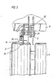
- the braking device 19 is arranged on the frame of the trailing roller 2 in the area of one of the two lower links.
- the braking device 19 acts on the tires 6 of the trailing roller 2 when the order combination is lifted from the ground by the tractor power lift at the end of a spreading passage.
- the braking device 19 consists of the two-armed lever 20.
- the lever 20 is pivotably mounted on the frame 8 of the trailing roller 2 by means of the lower link connecting bolt 21.
- the lever 20 has the driver pin 22 on one side of the lever.
- the lever 20 is thus pivotally mounted about the lower link pin 21.
- the lower link 5 is arranged on the frame 8 of the seed drill with the lower link connecting bolt 21.
- the lower link 5 has the elongated hole 23 through which the bolt 21 is inserted, so that the lower link 5 is vertically movable relative to the frame 8 of the trailing roller or the seeder.
- the other side of the lever has the skid 24, which is pressed against one of the tires 6 of the trailing roller 2 in the raised state of the tires or the roller or the seeder. As a result, the tire or roller 2 is braked and held.
- the lever 20 or the skid 24 takes the position shown in dash-dotted lines, ie the skid 24 is pressed against the tire 6 of the trailing roller 2.
- the lever 20 is held by the tension spring 25 in the position shown by solid lines.
- the part of the lever 20 on which the runner 24 is located is resilient. Characterized in that the skid 24 of the braking device is pressed against the tire 6 of the trailing roller 2, it is ensured that the trailing roller can no longer rotate after it has been lifted off the ground, that is to say after the ordering combination has been lifted, so that, of course, no longer
- the metering elements 10 can be driven via the control gear 13. This ensures in any case that no more seeds are fed to the coulters 16 immediately after the application process has ended, ie after the order combination has been lifted.
- Dig. 4 shows a further seeder 26, which is also saddled on a trailing roller 2.
- This seeder also has metering elements which feed the seed located in the reservoir 27 of the seeder 26 to the coulters, not shown.
- the metering elements 28, which are shown with dashed lines, are driven by the metering roller 2 via the regulating gear 29 and the drive mechanism 30 when they roll off the ground.
- the switchable clutch 32 is arranged between the drive mechanism 30 and the input shaft 31 of the control gear 29.
- This switchable clutch 32 has an actuating device, by means of which the clutch 32 can be disengaged when the seed drill 26 is lifted and the clutch can be engaged when and when the distributor is lowered. This actuating device can be switchable by hand.
- switching elements are preferably arranged on the lifting device of the seeder 26, via which the coupling 32 is then automatically connected when the seed drill is lifted, via a connecting line. ie when the trailing roller 2 is lifted off the floor, the drive is automatically interrupted and when the seed drill is lowered onto the ground, so that the trailing roller 2 rolls on the ground, and is engaged again at the start of the spreading operation.
Landscapes
- Life Sciences & Earth Sciences (AREA)
- Soil Sciences (AREA)
- Environmental Sciences (AREA)
- Sowing (AREA)
- Agricultural Machines (AREA)
Applications Claiming Priority (2)
| Application Number | Priority Date | Filing Date | Title |
|---|---|---|---|
| DE19873709526 DE3709526A1 (de) | 1987-03-25 | 1987-03-25 | Verteilmaschine |
| DE3709526 | 1987-03-25 |
Related Child Applications (2)
| Application Number | Title | Priority Date | Filing Date |
|---|---|---|---|
| EP19900109752 Division EP0389004A3 (fr) | 1987-03-25 | 1988-03-15 | Distributeur |
| EP90109752.7 Division-Into | 1990-05-22 |
Publications (2)
| Publication Number | Publication Date |
|---|---|
| EP0284870A1 true EP0284870A1 (fr) | 1988-10-05 |
| EP0284870B1 EP0284870B1 (fr) | 1991-07-10 |
Family
ID=6323800
Family Applications (2)
| Application Number | Title | Priority Date | Filing Date |
|---|---|---|---|
| EP19900109752 Withdrawn EP0389004A3 (fr) | 1987-03-25 | 1988-03-15 | Distributeur |
| EP88104050A Expired - Lifetime EP0284870B1 (fr) | 1987-03-25 | 1988-03-15 | Distributeur |
Family Applications Before (1)
| Application Number | Title | Priority Date | Filing Date |
|---|---|---|---|
| EP19900109752 Withdrawn EP0389004A3 (fr) | 1987-03-25 | 1988-03-15 | Distributeur |
Country Status (2)
| Country | Link |
|---|---|
| EP (2) | EP0389004A3 (fr) |
| DE (2) | DE3709526A1 (fr) |
Families Citing this family (1)
| Publication number | Priority date | Publication date | Assignee | Title |
|---|---|---|---|---|
| DE102010025944A1 (de) * | 2010-07-02 | 2012-01-05 | Kverneland Asa | Schalteinrichtung für eine landwirtschaftliche Verteilmaschine zum Ausbringen von Saatgut und/oder Dünger |
Citations (3)
| Publication number | Priority date | Publication date | Assignee | Title |
|---|---|---|---|---|
| DE7434244U (de) * | 1975-06-19 | Gebr Koeckerling Maschinenfabrik | Landwirtschaftliches Bestellgerät | |
| US4068452A (en) * | 1976-03-11 | 1978-01-17 | Allis-Chalmers Corporation | Mower spindle and spindle drive belt braking arrangement for rotary mower having plurality of mower spindles |
| FR2567716A1 (fr) * | 1984-07-18 | 1986-01-24 | Rolland Sa Ets | Machine agricole de pose de film sur des semis |
Family Cites Families (3)
| Publication number | Priority date | Publication date | Assignee | Title |
|---|---|---|---|---|
| US1327089A (en) * | 1913-09-15 | 1920-01-06 | Int Harvester Co | Seed-planter |
| US1441764A (en) * | 1919-11-21 | 1923-01-09 | Emerson Brantingham Co | Planter |
| DE3536695A1 (de) * | 1985-10-15 | 1987-04-16 | Amazonen Werke Dreyer H | Pneumatikduengerstreuer |
-
1987
- 1987-03-25 DE DE19873709526 patent/DE3709526A1/de not_active Withdrawn
-
1988
- 1988-03-15 EP EP19900109752 patent/EP0389004A3/fr not_active Withdrawn
- 1988-03-15 DE DE8888104050T patent/DE3863566D1/de not_active Expired - Lifetime
- 1988-03-15 EP EP88104050A patent/EP0284870B1/fr not_active Expired - Lifetime
Patent Citations (3)
| Publication number | Priority date | Publication date | Assignee | Title |
|---|---|---|---|---|
| DE7434244U (de) * | 1975-06-19 | Gebr Koeckerling Maschinenfabrik | Landwirtschaftliches Bestellgerät | |
| US4068452A (en) * | 1976-03-11 | 1978-01-17 | Allis-Chalmers Corporation | Mower spindle and spindle drive belt braking arrangement for rotary mower having plurality of mower spindles |
| FR2567716A1 (fr) * | 1984-07-18 | 1986-01-24 | Rolland Sa Ets | Machine agricole de pose de film sur des semis |
Also Published As
| Publication number | Publication date |
|---|---|
| DE3709526A1 (de) | 1988-10-13 |
| EP0389004A3 (fr) | 1990-11-28 |
| EP0389004A2 (fr) | 1990-09-26 |
| DE3863566D1 (de) | 1991-08-14 |
| EP0284870B1 (fr) | 1991-07-10 |
Similar Documents
| Publication | Publication Date | Title |
|---|---|---|
| EP3453238B1 (fr) | Engin agricole tracté | |
| DE2519209A1 (de) | Bodenbearbeitungsmaschine | |
| EP0281761B1 (fr) | Semoir monograine | |
| EP0310856A2 (fr) | Combinaisons de culture et de semis | |
| DE2659523C2 (de) | Sämaschine | |
| DE2528930A1 (de) | Tragrahmen fuer landwirtschaftliche maschinen und geraete | |
| EP0327869B1 (fr) | Machine combinée de culture et de semis | |
| EP0284870B1 (fr) | Distributeur | |
| CH711399A1 (de) | Landwirtschaftliche Maschine zum Bearbeiten eines Bodens und zum Ausbringen von Saatgut. | |
| DE60106677T2 (de) | Sämaschine | |
| EP0356606B1 (fr) | Semoir monograine | |
| DE3719270C2 (de) | Verteilmaschine | |
| EP0650660A1 (fr) | Distributeur de produits granulés | |
| DE2628798B2 (de) | Anbauvorrichtung für Schleuderdüngerstreuer | |
| DE19826295A1 (de) | Gezogene landwirtschaftliche Bestellkombination | |
| DE202018106093U1 (de) | Verteilmaschine | |
| EP0201049B1 (fr) | Semoir pneumatique monograine | |
| DE19821394A1 (de) | Gezogene landwirtschaftliche Bestellkombination | |
| EP0223133A1 (fr) | Semoir | |
| DE3615818A1 (de) | Verteilmaschine | |
| EP0752202A2 (fr) | Bâti de support pour machine agricole de travail du sol et/ou semence | |
| DE3114610C2 (fr) | ||
| DE253253C (fr) | ||
| EP0281932A2 (fr) | Machine à distribuer | |
| EP4616690A1 (fr) | Outil agricole |
Legal Events
| Date | Code | Title | Description |
|---|---|---|---|
| PUAI | Public reference made under article 153(3) epc to a published international application that has entered the european phase |
Free format text: ORIGINAL CODE: 0009012 |
|
| AK | Designated contracting states |
Kind code of ref document: A1 Designated state(s): DE FR GB IT NL |
|
| 17P | Request for examination filed |
Effective date: 19880826 |
|
| 17Q | First examination report despatched |
Effective date: 19900307 |
|
| GRAA | (expected) grant |
Free format text: ORIGINAL CODE: 0009210 |
|
| ITF | It: translation for a ep patent filed | ||
| AK | Designated contracting states |
Kind code of ref document: B1 Designated state(s): DE FR GB IT NL |
|
| XX | Miscellaneous (additional remarks) |
Free format text: TEILANMELDUNG 90109752.7 EINGEREICHT AM 15/03/88. |
|
| ET | Fr: translation filed | ||
| GBT | Gb: translation of ep patent filed (gb section 77(6)(a)/1977) | ||
| REF | Corresponds to: |
Ref document number: 3863566 Country of ref document: DE Date of ref document: 19910814 |
|
| PLBI | Opposition filed |
Free format text: ORIGINAL CODE: 0009260 |
|
| 26 | Opposition filed |
Opponent name: RABEWERK GMBH + CO. Effective date: 19920401 |
|
| NLR1 | Nl: opposition has been filed with the epo |
Opponent name: RABEWERK GMBH |
|
| PLBN | Opposition rejected |
Free format text: ORIGINAL CODE: 0009273 |
|
| STAA | Information on the status of an ep patent application or granted ep patent |
Free format text: STATUS: OPPOSITION REJECTED |
|
| 27O | Opposition rejected |
Effective date: 19931109 |
|
| NLR2 | Nl: decision of opposition | ||
| PGFP | Annual fee paid to national office [announced via postgrant information from national office to epo] |
Ref country code: NL Payment date: 19950331 Year of fee payment: 8 |
|
| PG25 | Lapsed in a contracting state [announced via postgrant information from national office to epo] |
Ref country code: NL Effective date: 19961001 |
|
| NLV4 | Nl: lapsed or anulled due to non-payment of the annual fee |
Effective date: 19961001 |
|
| PGFP | Annual fee paid to national office [announced via postgrant information from national office to epo] |
Ref country code: GB Payment date: 19981222 Year of fee payment: 12 |
|
| PG25 | Lapsed in a contracting state [announced via postgrant information from national office to epo] |
Ref country code: GB Free format text: LAPSE BECAUSE OF NON-PAYMENT OF DUE FEES Effective date: 20000315 |
|
| GBPC | Gb: european patent ceased through non-payment of renewal fee |
Effective date: 20000315 |
|
| PGFP | Annual fee paid to national office [announced via postgrant information from national office to epo] |
Ref country code: FR Payment date: 20030328 Year of fee payment: 16 |
|
| PGFP | Annual fee paid to national office [announced via postgrant information from national office to epo] |
Ref country code: DE Payment date: 20040331 Year of fee payment: 17 |
|
| PG25 | Lapsed in a contracting state [announced via postgrant information from national office to epo] |
Ref country code: FR Free format text: LAPSE BECAUSE OF NON-PAYMENT OF DUE FEES Effective date: 20041130 |
|
| REG | Reference to a national code |
Ref country code: FR Ref legal event code: ST |
|
| PG25 | Lapsed in a contracting state [announced via postgrant information from national office to epo] |
Ref country code: IT Free format text: LAPSE BECAUSE OF NON-PAYMENT OF DUE FEES;WARNING: LAPSES OF ITALIAN PATENTS WITH EFFECTIVE DATE BEFORE 2007 MAY HAVE OCCURRED AT ANY TIME BEFORE 2007. THE CORRECT EFFECTIVE DATE MAY BE DIFFERENT FROM THE ONE RECORDED. Effective date: 20050315 |
|
| PG25 | Lapsed in a contracting state [announced via postgrant information from national office to epo] |
Ref country code: DE Free format text: LAPSE BECAUSE OF NON-PAYMENT OF DUE FEES Effective date: 20051001 |