EP0284977A1 - Moteur hydraulique lent et réversible à travail massique élevé - Google Patents
Moteur hydraulique lent et réversible à travail massique élevé Download PDFInfo
- Publication number
- EP0284977A1 EP0284977A1 EP88104632A EP88104632A EP0284977A1 EP 0284977 A1 EP0284977 A1 EP 0284977A1 EP 88104632 A EP88104632 A EP 88104632A EP 88104632 A EP88104632 A EP 88104632A EP 0284977 A1 EP0284977 A1 EP 0284977A1
- Authority
- EP
- European Patent Office
- Prior art keywords
- piston
- plates
- tooth
- teeth
- motor according
- Prior art date
- Legal status (The legal status is an assumption and is not a legal conclusion. Google has not performed a legal analysis and makes no representation as to the accuracy of the status listed.)
- Withdrawn
Links
- 230000002441 reversible effect Effects 0.000 title claims abstract description 7
- 230000001360 synchronised effect Effects 0.000 claims 2
- 208000006011 Stroke Diseases 0.000 description 13
- 239000012530 fluid Substances 0.000 description 13
- 238000006073 displacement reaction Methods 0.000 description 5
- 230000007717 exclusion Effects 0.000 description 2
- 238000005452 bending Methods 0.000 description 1
Images


Classifications
-
- F—MECHANICAL ENGINEERING; LIGHTING; HEATING; WEAPONS; BLASTING
- F16—ENGINEERING ELEMENTS AND UNITS; GENERAL MEASURES FOR PRODUCING AND MAINTAINING EFFECTIVE FUNCTIONING OF MACHINES OR INSTALLATIONS; THERMAL INSULATION IN GENERAL
- F16H—GEARING
- F16H31/00—Other gearings with freewheeling members or other intermittently driving members
- F16H31/007—Step-by-step mechanisms for linear motion
-
- F—MECHANICAL ENGINEERING; LIGHTING; HEATING; WEAPONS; BLASTING
- F15—FLUID-PRESSURE ACTUATORS; HYDRAULICS OR PNEUMATICS IN GENERAL
- F15B—SYSTEMS ACTING BY MEANS OF FLUIDS IN GENERAL; FLUID-PRESSURE ACTUATORS, e.g. SERVOMOTORS; DETAILS OF FLUID-PRESSURE SYSTEMS, NOT OTHERWISE PROVIDED FOR
- F15B15/00—Fluid-actuated devices for displacing a member from one position to another; Gearing associated therewith
- F15B15/02—Mechanical layout characterised by the means for converting the movement of the fluid-actuated element into movement of the finally-operated member
- F15B15/06—Mechanical layout characterised by the means for converting the movement of the fluid-actuated element into movement of the finally-operated member for mechanically converting rectilinear movement into non- rectilinear movement
- F15B15/065—Mechanical layout characterised by the means for converting the movement of the fluid-actuated element into movement of the finally-operated member for mechanically converting rectilinear movement into non- rectilinear movement the motor being of the rack-and-pinion type
-
- F—MECHANICAL ENGINEERING; LIGHTING; HEATING; WEAPONS; BLASTING
- F16—ENGINEERING ELEMENTS AND UNITS; GENERAL MEASURES FOR PRODUCING AND MAINTAINING EFFECTIVE FUNCTIONING OF MACHINES OR INSTALLATIONS; THERMAL INSULATION IN GENERAL
- F16H—GEARING
- F16H27/00—Step-by-step mechanisms without freewheel members, e.g. Geneva drives
- F16H27/02—Step-by-step mechanisms without freewheel members, e.g. Geneva drives with at least one reciprocating or oscillating transmission member
Definitions
- the present invention relates to a hydraulic slow and reversible motor, with high specific work.
- Rotary hydraulic motors with pistons of significant displacement and rotary hydraulic motors with small rating at high number of revolutions per minute are well known.
- the latters are keyed on mechanical reduction units which convert the work supplied by the motor at high speed into correspondent adequate work at low speed.
- Another drawback consists in that, when the stroke is increased considerably, the relevant weight, although lower than corresponding rotary motors, becomes considerably high.
- a further drawback consists in that, when used to drive a rotating machine member, they must be hinged on supporting structures with remarkable sizes to withstand the significant bending loads generated in the system.
- the hi-speed rotary motors with low rating which may be coupled to a mechanical reduction unit, have reduced sizes, weight and cost, but need the use of a reduction units of high weight and dimensions.
- An aim of the invention is to realize a hydraulic slow and reversible motor which may generate, having very limited dimension, a high work, even with limited power rating.
- Another aim of the invention is to realize a hydraulic motor of reversible type.
- Another aim of the invention is to realize a hydraulic motor without dead centers and which remains constantly engaged with the driven member.
- a slow hydraulic reversible motor with high specific work characterized by comprising a virtual rack of infinite length generated by a hydraulic actuator with linear reciprocating motion and by at least a couple of teeth engaging alternately with the teeth of a gear to be driven.
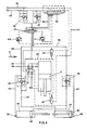
- the motor according to the invention comprises an assembly cylinder 1 - piston 2 connected to a hydraulic power unit 3, which shall be further described in details.
- the stem 4 of the piston 2 is connected, outside the cylinder 1, to a cross pin 5 having its ends engaged with two plates 6,7 which move parallely alongside said stem 4.
- Both plates 6,7 present four horizontal slots 8, crossed by pins 9 fixed to the main machine frame, where also cylinder 1 is mounted.
- Two racks 10,11 are mounted near the inner opposite faces of plates 6,7.
- rack 10 protrudes more than rack 11 and both racks engage with two pinions 12,13 located, as their corresponding racks, at two different levels and supported respectively by pins 14 and 15 integral with the main machine frame.
- the pins 9, supporting plates 6,7, also support two plates 16,17; with respect to stem 4 the plate 16 is located on the same side as plate 6, but is distant from pins 14,15 as much as plate 7.
- the plate 17 is located, with respect to stem 4, on the same side of plate 7, but is distant from pins 14,15 as much as plate 6, engaging with pinion 12; on the plate 16 is mounted, at the same level of rack 10, a rack 19 engaging with pinion 12.
- Each tooth 22,23 is substantially formed by a metallic body of roughly prismatic shape with lower outline suitable to engage with the teeth of a wheel 24 or of a rack, which are the members to be driven.
- the plates 6,17 integral with the housings 20,21 of the teeth 22,23 present a slot which allows said teeth to move transversally through; the teeth are moved along their axis towards corresponding plate 7,16 by respectively hydraulic actuators 28, whose cylinder 25,27 is freely housed in the tooth body 22,23 and whose piston 26,29 is fixed to the said body by the free end of its stem.
- a hydraulic circuit controlling the movements of the pistons 26,29 in either directions is connected to power unit 3.
- Each plate 16,7 adjacent internally to plate 6,17, supporting the corresponding tooth 22,23 presents an opening 30 with larger sizes to allow as it will be explained after, the mutual cross movements of other respective tooth 23,22.
- the power unit 3, operating the two actuators 28 of the teeth 22,23 and the assembly cylinder 1 - piston 2 comprises: - one twelve-ways flow deviation device 32 and a double distributor 33, - a first couple of sequence valves 34,35, the one 34 being located between the distributor 33 and the inlet side of the cylinder 27 (inlet side denominates the portion of cylindrical room which includes the piston stem); the other 35 is placed between distibutor 33 and inlet side of the other cylinder 25, - a second couple of sequence valves 36,37 located between the delivery duct 38, return duct 39 and distributor 33, - a couple of pressure relief valves 40,41 located in the circuit controlling the spool of distributor 33, - a first couple of interception valves 42,43 actuated by the main piston 2, near the two stroke-end positions, suitable to intercept the duct 44 controlling the spool of distibutor 33, - four piloted block valves 45,46,47,48 controlling the assembly cylinder 1 - piston 2, - a quantity of
- the fluid coming from the duct 38 may enter directly the distributor 33 through the duct 55, without passing through the sequence valve 37, and goes out from duct 56 to split in two branches, one entering directly, through the duct 57, the outlet side of the cylinder 27, thus causing relevant piston 29 to protrude, the other entering the inlet side of cylinder 25, after having passed through the sequence valve 35, which function is to allow the flow of the fluid only after that the piston 29 has reached its stroke-end.
- the two ducts 38,39 in the power unit 3 must be exchanged eachother; in such a way first the flow deviation device 32 is operated, as to invert the feeding cycle of the cylinder 1, without however modifying the feeding cycle of the two cylinders 25,27 actuating the teeth 22,23.
- This exchange of the fluid feeding ducts 38,39 shall cause the sequence valve 36 to operate instead of the 37, all other considerations made insofar remaining unchanged.
- the hydraulic motor according to the invention is based on the principle of creating, with reciprocating movement of teeth 22,23, a virtual rack to be engaged with a wheel 24 or with a rack in order to actuate by means of this a machine member whatsoever.
- the motor according to the invention has sizes significantly smaller, for the same quantity or work supplied, and therefore implies much lower weight and cost.
Landscapes
- Engineering & Computer Science (AREA)
- General Engineering & Computer Science (AREA)
- Mechanical Engineering (AREA)
- Physics & Mathematics (AREA)
- Fluid Mechanics (AREA)
- Hydraulic Motors (AREA)
Applications Claiming Priority (2)
| Application Number | Priority Date | Filing Date | Title |
|---|---|---|---|
| IT4156287 | 1987-03-25 | ||
| IT8741562A IT1229966B (it) | 1987-03-25 | 1987-03-25 | Motore idraulico a corsa teoricamente illimitata, autonomo, automaticoe a moto reversibile, per la trasmissione di alte coppie o traslazioni lineari con alte forze in gioco |
Publications (1)
| Publication Number | Publication Date |
|---|---|
| EP0284977A1 true EP0284977A1 (fr) | 1988-10-05 |
Family
ID=11251216
Family Applications (2)
| Application Number | Title | Priority Date | Filing Date |
|---|---|---|---|
| EP88903209A Pending EP0382718A1 (fr) | 1987-03-25 | 1988-03-23 | Moteur lent reversible a fonctionnement hydraulique, avec puissance motrice specifique elevee |
| EP88104632A Withdrawn EP0284977A1 (fr) | 1987-03-25 | 1988-03-23 | Moteur hydraulique lent et réversible à travail massique élevé |
Family Applications Before (1)
| Application Number | Title | Priority Date | Filing Date |
|---|---|---|---|
| EP88903209A Pending EP0382718A1 (fr) | 1987-03-25 | 1988-03-23 | Moteur lent reversible a fonctionnement hydraulique, avec puissance motrice specifique elevee |
Country Status (4)
| Country | Link |
|---|---|
| EP (2) | EP0382718A1 (fr) |
| AU (1) | AU1592988A (fr) |
| IT (1) | IT1229966B (fr) |
| WO (1) | WO1988007640A1 (fr) |
Citations (3)
| Publication number | Priority date | Publication date | Assignee | Title |
|---|---|---|---|---|
| GB191010578A (en) * | 1909-05-01 | 1900-01-01 | Coatgoureden Alain | A Device for Converting the Reciprocating Motion of a Piston Rod into Continuous Circular Motion. |
| FR1595665A (fr) * | 1968-10-31 | 1970-06-15 | ||
| FR2156301A1 (fr) * | 1971-10-13 | 1973-05-25 | English Numbering Machines |
-
1987
- 1987-03-25 IT IT8741562A patent/IT1229966B/it active
-
1988
- 1988-03-23 EP EP88903209A patent/EP0382718A1/fr active Pending
- 1988-03-23 AU AU15929/88A patent/AU1592988A/en not_active Abandoned
- 1988-03-23 EP EP88104632A patent/EP0284977A1/fr not_active Withdrawn
- 1988-03-23 WO PCT/EP1988/000236 patent/WO1988007640A1/fr not_active Ceased
Patent Citations (3)
| Publication number | Priority date | Publication date | Assignee | Title |
|---|---|---|---|---|
| GB191010578A (en) * | 1909-05-01 | 1900-01-01 | Coatgoureden Alain | A Device for Converting the Reciprocating Motion of a Piston Rod into Continuous Circular Motion. |
| FR1595665A (fr) * | 1968-10-31 | 1970-06-15 | ||
| FR2156301A1 (fr) * | 1971-10-13 | 1973-05-25 | English Numbering Machines |
Also Published As
| Publication number | Publication date |
|---|---|
| WO1988007640A1 (fr) | 1988-10-06 |
| EP0382718A1 (fr) | 1990-08-22 |
| AU1592988A (en) | 1988-11-02 |
| IT8741562A0 (it) | 1987-03-25 |
| IT1229966B (it) | 1991-09-20 |
Similar Documents
| Publication | Publication Date | Title |
|---|---|---|
| US3769881A (en) | Hydraulic device | |
| KR870008115A (ko) | 펌프조립체와 그 작동방법 | |
| US3800669A (en) | Control valve arrangement for a hydraulic drive | |
| US3332323A (en) | Rotary actuator | |
| US5173036A (en) | Method and an arrangement for controlling a linear motor | |
| US3148628A (en) | Hydraulic apparatus | |
| WO1988007640A1 (fr) | Moteur lent reversible a fonctionnement hydraulique, avec puissance motrice specifique elevee | |
| GB2380968A (en) | Single-motor injection and screw drive hybrid actuator | |
| CN119196121A (zh) | 一种齿轮摆动油缸及其使用方法和设备 | |
| US3720484A (en) | Hydraulic pressure transformer | |
| US3172332A (en) | Fluid operated motor | |
| CN111456976B (zh) | 泵送机械液压系统及泵送机械 | |
| DE10240334B4 (de) | Elektrohydraulischer Aktuator | |
| US3453935A (en) | Mine roof support systems | |
| RU2109946C1 (ru) | Гидромеханический привод горной машины | |
| US3670627A (en) | Device for driving a shaft in rotation | |
| KR830008807A (ko) | 전자-유압 로보트 위치제어 시스템 | |
| SU1216457A1 (ru) | Электрогидравлический привод с переменной структурой | |
| US4044654A (en) | Hydraulic engine | |
| SU1038640A1 (ru) | Поршневой гидродвигатель | |
| SU1154493A1 (ru) | Гидропривод | |
| RU2351451C1 (ru) | Шаговый привод подач | |
| DE69016638D1 (de) | Kolbenpumpe oder kolbenpumpe und motorkonstruktion. | |
| KR200143022Y1 (ko) | 머시닝센터의 테이블 회전장치 | |
| RU2138649C1 (ru) | Поршневая машина |
Legal Events
| Date | Code | Title | Description |
|---|---|---|---|
| PUAI | Public reference made under article 153(3) epc to a published international application that has entered the european phase |
Free format text: ORIGINAL CODE: 0009012 |
|
| AK | Designated contracting states |
Kind code of ref document: A1 Designated state(s): ES GR |
|
| 17P | Request for examination filed |
Effective date: 19890328 |
|
| RBV | Designated contracting states (corrected) |
Designated state(s): DE ES FR GB GR |
|
| XX | Miscellaneous (additional remarks) |
Free format text: VERBUNDEN MIT 88903209.0/0382718 (EUROPAEISCHE ANMELDENUMMER/VEROEFFENTLICHUNGSNUMMER) DURCH ENTSCHEIDUNG VOM 15.03.91. |
|
| 17Q | First examination report despatched |
Effective date: 19910412 |
|
| STAA | Information on the status of an ep patent application or granted ep patent |
Free format text: STATUS: THE APPLICATION IS DEEMED TO BE WITHDRAWN |
|
| 18D | Application deemed to be withdrawn |
Effective date: 19910823 |