EP0284990A2 - Elektronenkanone für eine Farbbildröhre - Google Patents
Elektronenkanone für eine Farbbildröhre Download PDFInfo
- Publication number
- EP0284990A2 EP0284990A2 EP88104669A EP88104669A EP0284990A2 EP 0284990 A2 EP0284990 A2 EP 0284990A2 EP 88104669 A EP88104669 A EP 88104669A EP 88104669 A EP88104669 A EP 88104669A EP 0284990 A2 EP0284990 A2 EP 0284990A2
- Authority
- EP
- European Patent Office
- Prior art keywords
- electron beams
- electron
- electrode
- phosphor screen
- voltage
- Prior art date
- Legal status (The legal status is an assumption and is not a legal conclusion. Google has not performed a legal analysis and makes no representation as to the accuracy of the status listed.)
- Granted
Links
- 238000010894 electron beam technology Methods 0.000 claims abstract description 77
- OAICVXFJPJFONN-UHFFFAOYSA-N Phosphorus Chemical compound [P] OAICVXFJPJFONN-UHFFFAOYSA-N 0.000 claims abstract description 45
- 230000004075 alteration Effects 0.000 description 35
- 230000000694 effects Effects 0.000 description 25
- 230000002093 peripheral effect Effects 0.000 description 18
- 230000005291 magnetic effect Effects 0.000 description 10
- 241001663154 Electron Species 0.000 description 2
- 229920000136 polysorbate Polymers 0.000 description 2
- 241000226585 Antennaria plantaginifolia Species 0.000 description 1
- 125000001475 halogen functional group Chemical group 0.000 description 1
- 238000000034 method Methods 0.000 description 1
- 238000012986 modification Methods 0.000 description 1
- 230000004048 modification Effects 0.000 description 1
- 230000000007 visual effect Effects 0.000 description 1
- 230000003313 weakening effect Effects 0.000 description 1
Images



Classifications
-
- H—ELECTRICITY
- H01—ELECTRIC ELEMENTS
- H01J—ELECTRIC DISCHARGE TUBES OR DISCHARGE LAMPS
- H01J29/00—Details of cathode-ray tubes or of electron-beam tubes of the types covered by group H01J31/00
- H01J29/46—Arrangements of electrodes and associated parts for generating or controlling the ray or beam, e.g. electron-optical arrangement
- H01J29/58—Arrangements for focusing or reflecting ray or beam
- H01J29/62—Electrostatic lenses
-
- H—ELECTRICITY
- H01—ELECTRIC ELEMENTS
- H01J—ELECTRIC DISCHARGE TUBES OR DISCHARGE LAMPS
- H01J29/00—Details of cathode-ray tubes or of electron-beam tubes of the types covered by group H01J31/00
- H01J29/46—Arrangements of electrodes and associated parts for generating or controlling the ray or beam, e.g. electron-optical arrangement
- H01J29/48—Electron guns
- H01J29/50—Electron guns two or more guns in a single vacuum space, e.g. for plural-ray tube
- H01J29/503—Three or more guns, the axes of which lay in a common plane
-
- H—ELECTRICITY
- H01—ELECTRIC ELEMENTS
- H01J—ELECTRIC DISCHARGE TUBES OR DISCHARGE LAMPS
- H01J29/00—Details of cathode-ray tubes or of electron-beam tubes of the types covered by group H01J31/00
- H01J29/46—Arrangements of electrodes and associated parts for generating or controlling the ray or beam, e.g. electron-optical arrangement
- H01J29/48—Electron guns
- H01J29/50—Electron guns two or more guns in a single vacuum space, e.g. for plural-ray tube
-
- H—ELECTRICITY
- H01—ELECTRIC ELEMENTS
- H01J—ELECTRIC DISCHARGE TUBES OR DISCHARGE LAMPS
- H01J2229/00—Details of cathode ray tubes or electron beam tubes
- H01J2229/48—Electron guns
- H01J2229/4834—Electrical arrangements coupled to electrodes, e.g. potentials
- H01J2229/4837—Electrical arrangements coupled to electrodes, e.g. potentials characterised by the potentials applied
- H01J2229/4841—Dynamic potentials
-
- H—ELECTRICITY
- H01—ELECTRIC ELEMENTS
- H01J—ELECTRIC DISCHARGE TUBES OR DISCHARGE LAMPS
- H01J2229/00—Details of cathode ray tubes or electron beam tubes
- H01J2229/48—Electron guns
- H01J2229/4844—Electron guns characterised by beam passing apertures or combinations
- H01J2229/4848—Aperture shape as viewed along beam axis
- H01J2229/4858—Aperture shape as viewed along beam axis parallelogram
- H01J2229/4865—Aperture shape as viewed along beam axis parallelogram rectangle
-
- H—ELECTRICITY
- H01—ELECTRIC ELEMENTS
- H01J—ELECTRIC DISCHARGE TUBES OR DISCHARGE LAMPS
- H01J2229/00—Details of cathode ray tubes or electron beam tubes
- H01J2229/48—Electron guns
- H01J2229/4844—Electron guns characterised by beam passing apertures or combinations
- H01J2229/4848—Aperture shape as viewed along beam axis
- H01J2229/4858—Aperture shape as viewed along beam axis parallelogram
- H01J2229/4865—Aperture shape as viewed along beam axis parallelogram rectangle
- H01J2229/4868—Aperture shape as viewed along beam axis parallelogram rectangle with rounded end or ends
-
- H—ELECTRICITY
- H01—ELECTRIC ELEMENTS
- H01J—ELECTRIC DISCHARGE TUBES OR DISCHARGE LAMPS
- H01J2229/00—Details of cathode ray tubes or electron beam tubes
- H01J2229/48—Electron guns
- H01J2229/4844—Electron guns characterised by beam passing apertures or combinations
- H01J2229/4848—Aperture shape as viewed along beam axis
- H01J2229/4872—Aperture shape as viewed along beam axis circular
Definitions
- the present invention relates to a color cathode ray tube, and more specifically to an improvement of an electron gun assembly thereof.
- an electron gun assembly of an inline type is used in a color cathode ray tube. It includes three electron guns arranged in line with one another.
- the resolution characteristic of the color cathode ray tube with this arrangement is lowered by a deflective aberration such that beam spots on a phosphor screen become greater as electron beams are deflected from the center region of the screen toward the peripheral region thereof.
- this aberration consists of two superposed deflective aberrations.
- a first deflective aberration is caused since the more the electron beams are deflected, the longer the paths of the electron beams from the electron guns to the phosphor screen become. If a proper focusing voltage is applied to the electron guns, the focused electron beams can form small enough beam spots in the center region of the phosphor screen. In the peripheral region of the screen, however, the electron beams are over-focused, so that the beam spots are subject to the deflective aberration.
- a second deflective aberration is caused due to the nonuniformity of deflection magnetic fields.
- a pincushion-shaped horizontal deflection magnetic field and a barrel-shaped vertical deflection magnetic field are formed as shown in Figs. 1A and 1B, respectively.
- Electron beams 21, 22 and 23 impinge on a same position of the phosphor screen by these magnetic fields.
- beams 21, 22 and 23 are subjected to a diverging effect in the horizontal direction and a converging effect in the vertical direction.
- the beams are distorted or extended horizontally.
- Such a deformation, i.e., deflective aberration is particularly great in the peripheral region of the phosphor screen, so that the resulting beam spots are noncircular.
- the electron beams are landed on the phosphor screen, tracing in the manner shown in Fig. 2.
- full lines indicate a path within a horizontal plane
- broken lines indicate a path within a vertical plane.
- the electron beams are under-focused on phosphor screen 18.
- the wider the deflection angle of the electron beams the longer is the beam path under the influence of the first deflective aberration. Accordingly, the electron beams are over-focused on phosphor screen 18.
- This over-focusing effect is reduced by the under-focusing effect produced under the influence of the second deflective aberration.
- a focusing plane within the horizontal direction is synthetically formed inside phosphor screen 18, that is, on the electron gun electron gun assembly side thereof.
- the electron beams within the horizontal and vertical planes, are deflected from the center region to the peripheral region of the phosphor screen in a manner such that the beams are focused on the center region, the beams are subjected to the converging effect, influenced by the second deflective aberration within the vertical plane, due to the presence of the nonuniform deflection magnetic field.
- the electron beams are over-focused on phosphor screen 18.
- the wider the deflection angle of the electron beams the longer is the beam path under the influence of the first deflective aberration. Accordingly, the electron beams are additionally over-focused on phosphor screen 18.
- a focusing plane within the vertical direction is synthetically formed inside the horizontal focusing plane 19, that is, on the assembly side thereof.
- circular beam spot 24 is formed in the center region of the phosphor screen, while noncircular beam spots, each consisting of high-luminance core 26 and low-luminance halo 27, are formed in the peripheral region of the screen. Thus, the resolution is degraded in the peripheral region.
- a quadra-potential electron gun assembly disclosed therein comprises cathodes 1 and first, second, third, fourth, fifth, and sixth grids 2, 3, 4, 5, 6 and 7, as shown in Fig. 4.
- Fourth grid 15 is composed of first, second, and third members 8, 9 and 10.
- First and third members 8 and 10 each have three electron circular beam apertures, while second member 9 have horizontally elongated, rectangular electron beam apertures 14
- Predetermined voltage V2 is applied to first and third members 8 and 10
- dynamic voltage Vd which changes depending on the deflection amount or deflection angle of the electron beams, is applied to second member 9.
- dynamic voltage Vd has the same level as predetermined voltage V2. As the deflection amount increases, the level of voltage Vd lowers gradually from V2. Thus, asymmetrical lenses are formed between three members 8, 9 and 10, which constitute fourth grid 5, only if the electron beams are deflected.
- the asymmetrical lenses apply strong and weak focusing effects to the electron beams passing through the lenses, within the vertical and horizontal planes, respectively. Accordingly, the electron beams should be deformed into the shape of an oval having its major axis within the horizontal plane, and should be incident on a main lens between fifth and sixth grids 6 and 7.
- dynamic voltage Vd In order to form the asymmetrical lenses, as seen from the electrode arrangement shown in Fig. 4, dynamic voltage Vd must be lowered as the deflection amount increases.
- the focusing power of a unipotential lens between third and fifth grids 4 and 6 is enhanced, so that the electron beams are positively over-focused on the peripheral region of the phosphor screen.
- the first deflective aberration becomes so great that the focusing effect of the electron beams in the peripheral region of the phosphor screen will be degraded.
- the oval-sectioned electron beams incident on the main lens are subjected to strong and weak focusing effects within the horizontal and vertical planes, respectively, due to the spherical aberration of the main lens.
- the deflective aberrations are said to be reduced, and the resolution is said to be restrained from being lowered in the peripheral region of the phosphor screen.
- the asymmetrical lens in order to form the horizontally elongated beam shape in the region between the asymmetrical lens and the main lens, the asymmetrical lens must function so as to converge the beams strongly in the vertical direction and so as to diverge or converge the beams weakly in the horizontal direction.
- Such astigmatic functions of the asymmetrical lens coincide with those of the second deflective aberration of the deflection yoke.
- the second deflective aberration will be also enhanced so that the resolution in the peripheral region of the phosphor screen may be degraded.
- the diverging effect within the vertical plane is exerted so that the beam spots are under-focused on phosphor screen 18.
- the beam spots can be prevented from being over-focused within the vertical plane due to the second deflective aberration.
- focusing plane 20 on which electron beams are focused in the vertical direction can be brought close to phosphor screen 18. Since the weak converging effect within the horizontal plane acts so that the beam spots are slightly over-focused, focusing plane 19 on which electron beams are focused in the horizontal direction is moved from the side of screen 18 toward the electron gun assembly. As a result, focusing planes 19 and 20 within the vertical and horizontal directions can be made coincident in the peripheral region of phosphor screen 18. Thus, the second deflective aberrations are reduced.
- the focusing plane within the horizontal and vertical directions are coincident in the peripheral region of phosphor screen 18, then they are formed on the same side of screen 18 as the electron gun assembly. Within the horizontal and vertical planes, therefore, the beam spots are over-focused and cannot have their minimum possible diameter. This is because asymmetrical lenses 16 are so much weaker than symmetrical lenses 17 that the first deflective aberration can be corrected only insufficiently although the second deflective aberration is properly corrected. Thus, the resolution in the peripheral region of the phosphor screen cannot be fully improved.
- this system should be combined with a dynamic focusing system such that the first deflective aberration is positively compensated by raising the voltage of fifth grid 6, as the deflection amount increases, weakening the focusing effect of main lens 15.
- This dynamic focusing system requires a voltage modulator circuit as well as dynamic voltage Vd.
- a dynamic focusing circuit requires withstand voltage compensation, since the reference voltage is at least several kilovolts. Thus, the visual display unit may possibly be increased in costs.
- the object of the present invention is to provide a color cathode ray tube ensuring high resolution throughout its phosphor screen.
- a color cathode ray tube comprising a phosphor screen; electron gun means for generating three electron beams toward the phosphor screen, the means including; cathode means for emitting the electron beams; first electrode means for accelerating and controlling the emitted electron beams; second electrode means for converging the accelerated and controlled electron beams on the phosphor screen and composed of first, second, and third electrode segments each having apertures through which the electron beams pass, individually; and third electron means for converging the electron beams passing through the second electrode means on the phosphor screen; deflection means for deflecting the electron beams to be landed the phosphor screen from the electron gun means in horizontal and vertical directions; and voltage applying means for applying a first variable voltage to the first and third electrode segments and applying a second constant voltage to the second electrode segment, the first variable voltage being varied in accordance with the deflection of the electron beam, whereby asymmetrical electron lenses are formed between the first and second electrode
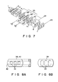
- Fig. 7 shows an electrode arrangement of a quadra-potential electron gun assembly of an in-line type incorporated in a color cathode ray tube according to an embodiment of the present invention.
- This electron gun assembly which has the same electrode arrangement as the one shown in Fig. 4, comprises cathodes 1 and first, second, third, fourth, fifth, and sixth grids 2, 3, 4, 35, 6 and 7.
- Fourth grid 35 is composed of first, second, and third members 38, 39 and 40.
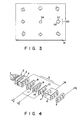
- Each of first and third members 38 and 40 has groove 42 extending in the horizontal direction and faced to second member 39, and three circular electron beam apertures 41 formed in the grove, as shown in Fig.
- second member 39 has vertically elongated rectangular electron beam apertures 43 arranged horizontally.
- electron beams emitted from cathodes 1 are focused on a phosphor screen by means of sub-lenses, which are formed between third and fourth grids 4 and 35 and between fourth and fifth grids 35 and 6, and a main lens between fifth and sixth grids 6 and 7. Then, the electron beams are landed on the phosphor screen after passing through magnetic fields formed by a deflection yoke 12, e.g., a horizontal deflection field of a pincushion type, as shown in Fig. 1A, and a vertical deflection field of a barrel type, as shown in Fig. 1B.
- a deflection yoke 12 e.g., a horizontal deflection field of a pincushion type, as shown in Fig. 1A, and a vertical deflection field of a barrel type, as shown in Fig. 1B.
- a DC potential of 50 to 150 V is applied to cathodes 1; 0 V to first grid 2, 600 to 800 V to second grid 3, 8 kV (VF) to third and fifth grids 4 and 6, and 27 kV (Va) to sixth grids 7.
- a DC potential of 600 to 800 V is applied to second member 39 of fourth grid 35, as well as to second grid 3.
- First and third members 38 and 40 of fourth grid 35 are supplied with dynamic voltage 29 which changes in synchronism with deflection current 28 applied to deflection yoke 12, as shown in Fig. 5B. If the amount of deflection of the electron beams is zero, dynamic voltage Vd has the same level as predetermined voltage V2. As the deflection amount increases, the level of voltage Vd rises gradually from V2.
- asymmetrical lenses 16 are formed between first and second members 38 and 39 of fourth grid 35 and between second and third members 39 and 40, as shown in Fig. 9.
- the converging effect of symmetrical sub-lenses, formed between third grid 4 and first member 38 of fourth grid 35 and between fifth grid 6 and third member 40 of fourth grid 35 is weakened.
- the converging effect of symmetrical sub-lenses 17, which are formed between third grid 4 and first member 38 of fourth grid 35 and between fifth grid 6 and third member 40 of fourth grid 35, is weakened. Therefore, the electron beams are subjected to an effect such that the beam spots within the vertical and horizontal planes are under-focused on phosphor screen 18.
- the beam spots are prevented, by the first deflective aberration, from being over-focused within the vertical and horizontal planes.
- the focusing plane within the horizontal and vertical directions move toward phosphor screen 18 to be in a alignment therewith.
- the first deflective aberration is compensated.
- the converging intensity of sub-lenses 17 shown in Fig. 9 is high enough to ensure a satisfactory effect of compensating the first deflective aberration.
- both the first and second deflective aberrations can be compensated in an optimum manner by means of signal dynamic voltage Vd.
- the deflective aberrations in the peripheral region of the phosphor screen are thoroughly suppressed, so that the beam sports are minimized in size.
- the resolution in the peripheral region can be improved considerably.
- the optimum value of dynamic voltage Vd obtained during diagonal deflection of the electron beams toward the peripheral region of the phosphor region was about 500 V, as compared with DC voltage V2 of 600 to 800 V applied to the second member of the fourth grid. Since the maximum value of dynamic voltage Vd is as low as about 1,300 V or less, the arrangement for voltage supply does not require any special consideration. Thus, the reliability of the electron gun assembly, including its withstand voltage characteristic, is high.
- first and third members 48 and 50 of a fourth grid each have circular electron beam apertures 51, and second member 49 has vertically elongated electron beam apertures 53.
- dynamic voltage 29 shown in Fig. 5B is applied to first and third members 48 and 50, and predetermined voltage V2 is applied to second member 49.
- first and third members 58 and 60 of a fourth grid each have circular electron beam apertures 61 and horizontally elongated groove 62 facing second member 59, and second member 59 has circular electron beam apertures 61, as shown in Fig. 11.
- voltages V2 applied to second member 59 of the fourth grid is equivalent to the voltage applied to second grid 3.
- the present invention is not limited to such an arrangement, and the same effect can be obtained as long as voltage V2 is constant.
- the deflective aberration attributable to the nonuniformity of the deflection fields and the deflective aberration attributable to the extended path of electron beams from the electron guns to the phosphor screen can both be compensated by applying one relatively low dynamic voltage.
- satisfactory resolution can be obtained throughout the phosphor screen.
Landscapes
- Video Image Reproduction Devices For Color Tv Systems (AREA)
- Cathode-Ray Tubes And Fluorescent Screens For Display (AREA)
Applications Claiming Priority (2)
| Application Number | Priority Date | Filing Date | Title |
|---|---|---|---|
| JP62074401A JPS63241842A (ja) | 1987-03-30 | 1987-03-30 | カラ−陰極線管 |
| JP74401/87 | 1987-03-30 |
Publications (3)
| Publication Number | Publication Date |
|---|---|
| EP0284990A2 true EP0284990A2 (de) | 1988-10-05 |
| EP0284990A3 EP0284990A3 (en) | 1989-05-17 |
| EP0284990B1 EP0284990B1 (de) | 1993-07-21 |
Family
ID=13546132
Family Applications (1)
| Application Number | Title | Priority Date | Filing Date |
|---|---|---|---|
| EP88104669A Expired - Lifetime EP0284990B1 (de) | 1987-03-30 | 1988-03-23 | Elektronenkanone für eine Farbbildröhre |
Country Status (6)
| Country | Link |
|---|---|
| US (1) | US4967120A (de) |
| EP (1) | EP0284990B1 (de) |
| JP (1) | JPS63241842A (de) |
| KR (1) | KR910000924B1 (de) |
| CN (1) | CN1038796C (de) |
| DE (1) | DE3882408T2 (de) |
Cited By (4)
| Publication number | Priority date | Publication date | Assignee | Title |
|---|---|---|---|---|
| DE4037029A1 (de) * | 1989-11-21 | 1991-05-29 | Gold Star Co | Elektronenkanone fuer eine farbkathodenstrahlroehre |
| FR2663154A1 (fr) * | 1990-06-07 | 1991-12-13 | Hitachi Ltd | Tube cathodique. |
| EP0670586A1 (de) * | 1994-03-01 | 1995-09-06 | Hitachi, Ltd. | Farbkathodenstrahlröhre |
| EP0693768A3 (de) * | 1994-07-19 | 1996-11-06 | Hitachi Ltd | Farbkathodenstrahlröhre mit niedrigen dynamischen Fokussierspannung |
Families Citing this family (10)
| Publication number | Priority date | Publication date | Assignee | Title |
|---|---|---|---|---|
| US5164640A (en) * | 1990-12-29 | 1992-11-17 | Samsung Electron Devices Co., Ltd. | Electron gun for cathode ray tube |
| KR940005500B1 (ko) * | 1991-12-17 | 1994-06-20 | 삼성전관 주식회사 | 칼라 음극선관용 전자총 |
| US5170101A (en) * | 1991-12-30 | 1992-12-08 | Zenith Electronics Corporation | Constant horizontal dimension symmetrical beam in-line electron gun |
| JPH06251722A (ja) * | 1993-02-24 | 1994-09-09 | Hitachi Ltd | 陰極線管 |
| JPH0721936A (ja) | 1993-06-30 | 1995-01-24 | Hitachi Ltd | 陰極線管 |
| KR970009209B1 (en) * | 1994-01-22 | 1997-06-07 | Lg Electronics Inc | In-line type electron gun for crt |
| US5977727A (en) * | 1997-05-09 | 1999-11-02 | Imaging & Sensing Technology Corporation | Electron beam profile and energy shaping lens |
| KR100274880B1 (ko) * | 1998-12-11 | 2001-01-15 | 김순택 | 칼라음극선관용 다이나믹 포커스 전자총 |
| JP2000251757A (ja) * | 1999-02-26 | 2000-09-14 | Toshiba Corp | 陰極線管 |
| US6987367B2 (en) * | 2003-06-10 | 2006-01-17 | Kabushiki Kaisha Toshiba | Cathode-ray tube |
Family Cites Families (7)
| Publication number | Priority date | Publication date | Assignee | Title |
|---|---|---|---|---|
| NL185815B (nl) * | 1954-03-11 | Bayer Ag | Werkwijze voor het bestrijden van micro-organismen alsmede gevormd voortbrengsel, geheel of ten dele bestaande uit materiaal, dat volgens deze werkwijze behandeld is. | |
| US4288718A (en) * | 1979-05-24 | 1981-09-08 | Zenith Radio Corporation | Means and method for beam spot distortion compensation in TV picture tubes |
| JPS6142841A (ja) * | 1984-08-02 | 1986-03-01 | Matsushita Electronics Corp | カラ−受像管装置 |
| JPS6174246A (ja) * | 1984-09-20 | 1986-04-16 | Toshiba Corp | カラ−受像管用電子銃 |
| JPH0719541B2 (ja) * | 1985-04-30 | 1995-03-06 | 株式会社日立製作所 | インライン型カラー受像管 |
| NL8600117A (nl) * | 1986-01-21 | 1987-08-17 | Philips Nv | Kleurenbeeldbuis met verminderde deflectie defocussering. |
| JP2569027B2 (ja) * | 1986-12-05 | 1997-01-08 | 株式会社日立製作所 | カラ−受像管用電子銃 |
-
1987
- 1987-03-30 JP JP62074401A patent/JPS63241842A/ja active Pending
-
1988
- 1988-03-23 DE DE88104669T patent/DE3882408T2/de not_active Expired - Lifetime
- 1988-03-23 EP EP88104669A patent/EP0284990B1/de not_active Expired - Lifetime
- 1988-03-29 KR KR1019880003461A patent/KR910000924B1/ko not_active Expired
- 1988-03-30 CN CN88101755A patent/CN1038796C/zh not_active Expired - Lifetime
-
1990
- 1990-02-23 US US07/484,004 patent/US4967120A/en not_active Expired - Lifetime
Cited By (11)
| Publication number | Priority date | Publication date | Assignee | Title |
|---|---|---|---|---|
| DE4037029A1 (de) * | 1989-11-21 | 1991-05-29 | Gold Star Co | Elektronenkanone fuer eine farbkathodenstrahlroehre |
| FR2663154A1 (fr) * | 1990-06-07 | 1991-12-13 | Hitachi Ltd | Tube cathodique. |
| EP0670586A1 (de) * | 1994-03-01 | 1995-09-06 | Hitachi, Ltd. | Farbkathodenstrahlröhre |
| US5625252A (en) * | 1994-03-01 | 1997-04-29 | Hitachi, Ltd. | Main lens structure for a color cathode ray tube |
| CN1082241C (zh) * | 1994-03-01 | 2002-04-03 | 株式会社日立制作所 | 彩色阴极射线管 |
| EP0877408A3 (de) * | 1994-03-01 | 2004-01-07 | Hitachi, Ltd. | Farbkathodenstrahlröhre |
| EP0693768A3 (de) * | 1994-07-19 | 1996-11-06 | Hitachi Ltd | Farbkathodenstrahlröhre mit niedrigen dynamischen Fokussierspannung |
| US5739631A (en) * | 1994-07-19 | 1998-04-14 | Hitachi, Ltd. | Color cathode ray tube having a low dynamic focus voltage |
| US6025674A (en) * | 1994-07-19 | 2000-02-15 | Hitachi Ltd. | Color cathode ray tube having a low dynamic focus voltage |
| US6331752B1 (en) | 1994-07-19 | 2001-12-18 | Hitachi, Ltd. | Color cathode ray tube having a low dynamic focus voltage |
| US6353282B1 (en) | 1994-07-19 | 2002-03-05 | Hitachi, Ltd. | Color cathode ray tube having a low dynamic focus |
Also Published As
| Publication number | Publication date |
|---|---|
| DE3882408T2 (de) | 1993-11-11 |
| EP0284990A3 (en) | 1989-05-17 |
| CN1031777A (zh) | 1989-03-15 |
| EP0284990B1 (de) | 1993-07-21 |
| KR910000924B1 (ko) | 1991-02-18 |
| CN1038796C (zh) | 1998-06-17 |
| JPS63241842A (ja) | 1988-10-07 |
| KR880011869A (ko) | 1988-10-31 |
| DE3882408D1 (de) | 1993-08-26 |
| US4967120A (en) | 1990-10-30 |
Similar Documents
| Publication | Publication Date | Title |
|---|---|---|
| US5300855A (en) | Electron gun for a color cathode ray tube | |
| USRE35548E (en) | Color display tube system with reduced spot growth | |
| US4945284A (en) | Electron gun for color-picture tube device | |
| USRE33592E (en) | Color display tube with reduced deflection defocussing | |
| US4935663A (en) | Electron gun assembly for color cathode ray tube apparatus | |
| EP0284990B1 (de) | Elektronenkanone für eine Farbbildröhre | |
| KR940000601Y1 (ko) | 음극선관용 전자총 | |
| KR100320490B1 (ko) | 컬러음극선관 | |
| US6339293B1 (en) | Cathoderay tube | |
| KR100312075B1 (ko) | 컬러 브라운관 장치 | |
| KR940008156Y1 (ko) | 칼라 음극선관용 전자총 | |
| KR950004627B1 (ko) | 칼라 음극선관용 전자총 | |
| US6404149B1 (en) | Cathode ray tube apparatus | |
| EP0388901B1 (de) | Farbkathodenstrahlröhre | |
| KR960016431B1 (ko) | 음극선관용 전자총 | |
| US5861710A (en) | Color cathode ray tube with reduced moire | |
| KR100248841B1 (ko) | 컬러음극선관 | |
| US6646381B2 (en) | Cathode-ray tube apparatus | |
| KR940003244Y1 (ko) | 음극선관용 전자총 | |
| US5668435A (en) | Color display system with color cathode ray tube having a high breakdown voltage | |
| JP3555207B2 (ja) | 陰極線管用電子銃 | |
| JPS63198241A (ja) | カラー陰極線管 | |
| EP0589522A1 (de) | Kathodenstrahlröhre | |
| KR940008763B1 (ko) | 칼라 음극선관용 전자총 | |
| KR100383857B1 (ko) | 컬러음극선관장치 |
Legal Events
| Date | Code | Title | Description |
|---|---|---|---|
| PUAI | Public reference made under article 153(3) epc to a published international application that has entered the european phase |
Free format text: ORIGINAL CODE: 0009012 |
|
| 17P | Request for examination filed |
Effective date: 19880420 |
|
| AK | Designated contracting states |
Kind code of ref document: A2 Designated state(s): DE FR GB |
|
| PUAL | Search report despatched |
Free format text: ORIGINAL CODE: 0009013 |
|
| AK | Designated contracting states |
Kind code of ref document: A3 Designated state(s): DE FR GB |
|
| 17Q | First examination report despatched |
Effective date: 19910412 |
|
| GRAA | (expected) grant |
Free format text: ORIGINAL CODE: 0009210 |
|
| AK | Designated contracting states |
Kind code of ref document: B1 Designated state(s): DE FR GB |
|
| REF | Corresponds to: |
Ref document number: 3882408 Country of ref document: DE Date of ref document: 19930826 |
|
| ET | Fr: translation filed | ||
| PLBE | No opposition filed within time limit |
Free format text: ORIGINAL CODE: 0009261 |
|
| STAA | Information on the status of an ep patent application or granted ep patent |
Free format text: STATUS: NO OPPOSITION FILED WITHIN TIME LIMIT |
|
| 26N | No opposition filed | ||
| REG | Reference to a national code |
Ref country code: GB Ref legal event code: 746 Effective date: 19981008 |
|
| REG | Reference to a national code |
Ref country code: FR Ref legal event code: D6 |
|
| REG | Reference to a national code |
Ref country code: GB Ref legal event code: IF02 |
|
| PGFP | Annual fee paid to national office [announced via postgrant information from national office to epo] |
Ref country code: DE Payment date: 20070315 Year of fee payment: 20 |
|
| PGFP | Annual fee paid to national office [announced via postgrant information from national office to epo] |
Ref country code: GB Payment date: 20070321 Year of fee payment: 20 |
|
| PGFP | Annual fee paid to national office [announced via postgrant information from national office to epo] |
Ref country code: FR Payment date: 20070308 Year of fee payment: 20 |
|
| PG25 | Lapsed in a contracting state [announced via postgrant information from national office to epo] |
Ref country code: GB Free format text: LAPSE BECAUSE OF EXPIRATION OF PROTECTION Effective date: 20080322 |