EP0285035A2 - Dispositif pour commuter un appareil électrique en fonction du tarif en vigueur - Google Patents
Dispositif pour commuter un appareil électrique en fonction du tarif en vigueur Download PDFInfo
- Publication number
- EP0285035A2 EP0285035A2 EP88104881A EP88104881A EP0285035A2 EP 0285035 A2 EP0285035 A2 EP 0285035A2 EP 88104881 A EP88104881 A EP 88104881A EP 88104881 A EP88104881 A EP 88104881A EP 0285035 A2 EP0285035 A2 EP 0285035A2
- Authority
- EP
- European Patent Office
- Prior art keywords
- tariff
- arrangement
- arrangement according
- valid
- switching
- Prior art date
- Legal status (The legal status is an assumption and is not a legal conclusion. Google has not performed a legal analysis and makes no representation as to the accuracy of the status listed.)
- Withdrawn
Links
Images
Classifications
-
- H—ELECTRICITY
- H02—GENERATION; CONVERSION OR DISTRIBUTION OF ELECTRIC POWER
- H02J—ELECTRIC POWER NETWORKS; CIRCUIT ARRANGEMENTS OR SYSTEMS FOR SUPPLYING OR DISTRIBUTING ELECTRIC POWER; SYSTEMS FOR STORING ELECTRIC ENERGY
- H02J13/00—Circuit arrangements for providing remote monitoring or remote control of equipment in a power distribution network
- H02J13/10—Circuit arrangements for providing remote monitoring or remote control of equipment in a power distribution network characterised by displaying of information or by user interaction, e.g. supervisory control and data acquisition [SCADA] systems
-
- Y—GENERAL TAGGING OF NEW TECHNOLOGICAL DEVELOPMENTS; GENERAL TAGGING OF CROSS-SECTIONAL TECHNOLOGIES SPANNING OVER SEVERAL SECTIONS OF THE IPC; TECHNICAL SUBJECTS COVERED BY FORMER USPC CROSS-REFERENCE ART COLLECTIONS [XRACs] AND DIGESTS
- Y04—INFORMATION OR COMMUNICATION TECHNOLOGIES HAVING AN IMPACT ON OTHER TECHNOLOGY AREAS
- Y04S—SYSTEMS INTEGRATING TECHNOLOGIES RELATED TO POWER NETWORK OPERATION, COMMUNICATION OR INFORMATION TECHNOLOGIES FOR IMPROVING THE ELECTRICAL POWER GENERATION, TRANSMISSION, DISTRIBUTION, MANAGEMENT OR USAGE, i.e. SMART GRIDS
- Y04S10/00—Systems supporting electrical power generation, transmission or distribution
- Y04S10/40—Display of information, e.g. of data or controls
Definitions
- the invention relates to an arrangement for switching an electrical device as a function of a valid tariff for electricity networks with at least two tariffs transmitted via a power network.
- a ripple control receiver is permanently installed in a hot water tank.
- the hot water storage tank is only switched on if a low tariff is signaled by a ripple control signal.
- the possible switch-on times are fixed to a single tariff, e.g. the night tariff, bound.
- An electricity meter is known from PCT application W0 81/035 41, in which information about the current power consumption, the total energy consumption and the valid tariff is transmitted to a display unit via the mains cable, e.g. can be arranged in a focus of consumption.
- the currently valid tariff is only displayed, but does not lead to any switching action.
- the consumer can be encouraged not to use time-bound consumption in low-load times, but is dependent on observing the tariff display.
- the object of the invention is therefore to provide an arrangement in such a way that a shift in energy consumption in low-load periods is possible through financial incentives without constant active intervention by the consumer.
- the arrangement has a display device for the currently valid tariff and is provided with a selector switch for preselecting a tariff, the associated electrical device being supplied with voltage only when the preselected tariff or a cheaper tariff is valid.
- the consumer determines up to which tariff he wants to operate a particular device.
- the consumer device then switches on or off independently on the basis of the applicable tariff.
- the consumer receives a financial incentive, which can be determined by the tariff structure, to switch on appliances as far as possible in low tariff times and thus to help to even out electricity consumption.
- the arrangement can advantageously be designed such that a voltage supply is interrupted as soon as the valid tariff becomes more expensive than the preselected one.
- the interruption of the voltage supply can only be made possible after a delay time has elapsed.
- the arrangement can be used flexibly if it has a plug for connection to sockets and a socket for connecting an electrical device.
- the arrangement can advantageously be carried out in such a way that when the arrangement is connected to the network, the display device flashes until the respectively valid tariff has been transmitted via the power network. This signals that the tariff displayed by the arrangement may not match the tariff that is currently valid.
- a tariff can be preselected manually using the selector switch, the display of the set tariff flashing until the valid tariff is updated by a signal received via the power network.
- the switching of the applicable tariff in the arrangement is expediently carried out by signals which are modulated onto the internal network in a central unit on the basis of corresponding ripple control signals.
- the information transmitted with different ripple control systems depending on the EVU district can be converted into a uniform code in the central unit.
- ripple control system not every single arrangement has to be adapted to the existing ripple control system.
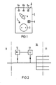
- a selector switch 4 is attached below the display device 6 and has three positions pointing to the lamps 6a to 6c.
- the arrangement is also provided with a socket 2, a voltage indicator 7 and an acoustic detector 8.
- a plug is provided on the rear side of the arrangement 1, not shown, a plug is provided with which the arrangement can be plugged into a socket.
- An electrical device can be connected to the socket 2 on the front of the arrangement.
- the selector switch 4 is set to the highest tariff level, for example assigned to the lamp 6a, there is in any case voltage at the socket 2, i.e. the connected electrical device can be operated independently of the applicable tariff.
- the voltage display 7 signals that there is voltage at the socket 2.
- the selector switch 4 is set to the middle tariff level signaled by the light 6b, voltage is only present at the socket 2 if this middle tariff level or the lowest tariff level is valid.
- the consumer can thus choose whether he wants to operate the connected device in any case, only while the middle or lowest tariff level is valid or only while the lowest tariff level is valid.
- the arrangement 1 can also be designed so that after a manual on circuit the voltage is switched off when a predetermined tariff is exceeded or a switched-off device is switched on when a preselected tariff is undershot.
- a change in the tariff levels can be indicated by the acoustic detector 8 by an acoustic signal.
- the RU transmits information about the nearest tariff. This information is essential because the consumer knows whether he can expect a lower or a higher tariff if he is still waiting for the start-up of an electrical device. Such information is therefore expediently shown in the display 6, for example by the lamp 6a, 6b or 6c assigned to the valid tariff lighting up continuously and the lamp 6a, 6b or 6c assigned to the next tariff flashing.
- Ripple control signals are contained in the power supply network 9, which contain corresponding switchover signals for tariffs. These ripple control signals are received by a ripple control receiver 12 in a central unit 10. In this case, the ripple control receiver 12 must be adapted to the respective power supply network, since the power supply companies use different ripple control systems.
- the tariff signal derived from the ripple control signal is fed to a transmitter 13, which converts these signals into uniform signals and modulates them onto the house network 11. So you get by with a uniform arrangement 1 for any utility network. Otherwise, each arrangement 1 would have to have an adaptability for all ripple control signals used in the power supply companies.
Landscapes
- Engineering & Computer Science (AREA)
- Power Engineering (AREA)
- Supply And Distribution Of Alternating Current (AREA)
- Remote Monitoring And Control Of Power-Distribution Networks (AREA)
Applications Claiming Priority (2)
| Application Number | Priority Date | Filing Date | Title |
|---|---|---|---|
| DE3710675 | 1987-03-31 | ||
| DE3710675 | 1987-03-31 |
Publications (2)
| Publication Number | Publication Date |
|---|---|
| EP0285035A2 true EP0285035A2 (fr) | 1988-10-05 |
| EP0285035A3 EP0285035A3 (fr) | 1989-12-27 |
Family
ID=6324455
Family Applications (1)
| Application Number | Title | Priority Date | Filing Date |
|---|---|---|---|
| EP88104881A Withdrawn EP0285035A3 (fr) | 1987-03-31 | 1988-03-25 | Dispositif pour commuter un appareil électrique en fonction du tarif en vigueur |
Country Status (1)
| Country | Link |
|---|---|
| EP (1) | EP0285035A3 (fr) |
Cited By (5)
| Publication number | Priority date | Publication date | Assignee | Title |
|---|---|---|---|---|
| AT405585B (de) * | 1997-08-06 | 1999-09-27 | Aski Ind Elektronik Gesmbh | Stromtarifabhängiges lastverlaufoptimierungssystem |
| EP0895333A3 (fr) * | 1997-07-29 | 1999-11-17 | ITF-EDV Fröschl GmbH | Système pour commander des charges en fonction de la consommation et/ou de la tarification, en particulier pour des charges électriques |
| DE102007023395A1 (de) * | 2007-05-18 | 2008-11-20 | Actaris Zähler & Systemtechnik GmbH | Anordnung zum Empfangen und Auswerten nachrichtentechnischer Signale |
| DE102010040033A1 (de) * | 2010-08-31 | 2012-03-01 | BSH Bosch und Siemens Hausgeräte GmbH | Hausgerät und Verfahren zum Betreiben eines Hausgeräts |
| EP2632022A4 (fr) * | 2010-10-19 | 2017-02-08 | Panasonic Intellectual Property Management Co., Ltd. | Dispositif de commande d'appareil et procédé de commande d'appareil |
Family Cites Families (4)
| Publication number | Priority date | Publication date | Assignee | Title |
|---|---|---|---|---|
| CH190202A (fr) * | 1935-07-31 | 1937-04-15 | Peloux Albert | Dispositif de commande de changement de tarif pour compteur électrique à double tarif. |
| CH359193A (de) * | 1957-03-11 | 1961-12-31 | Licentia Gmbh | Elektrogerät, das mit Hilfe einer Rundsteueranlage fernschaltbar ist |
| SE429378B (sv) * | 1980-06-06 | 1983-08-29 | Bjorn G Karlsson | Mikrodatorbaserad elmetare |
| DE3781178D1 (de) * | 1986-01-15 | 1992-09-24 | Merlin Gerin | Stromunterbrechungsrelais, insbesondere "zum ausschalten bei spitzen zeiten". |
-
1988
- 1988-03-25 EP EP88104881A patent/EP0285035A3/fr not_active Withdrawn
Cited By (5)
| Publication number | Priority date | Publication date | Assignee | Title |
|---|---|---|---|---|
| EP0895333A3 (fr) * | 1997-07-29 | 1999-11-17 | ITF-EDV Fröschl GmbH | Système pour commander des charges en fonction de la consommation et/ou de la tarification, en particulier pour des charges électriques |
| AT405585B (de) * | 1997-08-06 | 1999-09-27 | Aski Ind Elektronik Gesmbh | Stromtarifabhängiges lastverlaufoptimierungssystem |
| DE102007023395A1 (de) * | 2007-05-18 | 2008-11-20 | Actaris Zähler & Systemtechnik GmbH | Anordnung zum Empfangen und Auswerten nachrichtentechnischer Signale |
| DE102010040033A1 (de) * | 2010-08-31 | 2012-03-01 | BSH Bosch und Siemens Hausgeräte GmbH | Hausgerät und Verfahren zum Betreiben eines Hausgeräts |
| EP2632022A4 (fr) * | 2010-10-19 | 2017-02-08 | Panasonic Intellectual Property Management Co., Ltd. | Dispositif de commande d'appareil et procédé de commande d'appareil |
Also Published As
| Publication number | Publication date |
|---|---|
| EP0285035A3 (fr) | 1989-12-27 |
Similar Documents
| Publication | Publication Date | Title |
|---|---|---|
| DE19605698C1 (de) | Anschlußeinrichtung für ein elektrisches Installationssystem | |
| EP2614568A1 (fr) | Procédé pour faire passer un appareil électroménager à un tarif de consommation plus avantageux, et appareil électroménager correspondant | |
| DE2743212C2 (de) | Elektrisches Gerät mit Rundsteuerempfänger, insbesondere Haushaltsgerät | |
| DE102010002914A1 (de) | Verfahren und Vorrichtung zur elektrischen Verbrauchs- und Erzeugungserfassung | |
| EP0285035A2 (fr) | Dispositif pour commuter un appareil électrique en fonction du tarif en vigueur | |
| EP0402654B1 (fr) | Dispositif de connexion pour la connexion d'appareils électriques | |
| DE19548639A1 (de) | Steuermodul | |
| EP0437696B1 (fr) | Dispositif de connexion commuable à distance | |
| DE19723617A1 (de) | Beleuchtungsanlage für Straßen, Plätze und Objekte | |
| DE3623805C2 (de) | Signalübertragungssystem | |
| DE69505634T2 (de) | Elektrisches System mit Steuerung des Leistungsbedarfs | |
| DE102012020803B4 (de) | Informationssteckdose | |
| AT410270B (de) | Verteilersystem | |
| EP0163915A2 (fr) | Installation électrique pour logement | |
| DE3234763A1 (de) | Fernbedienbarer schalter | |
| DE202020002181U1 (de) | Modulare Multilevel Steckdosenleiste | |
| DE102020002958A1 (de) | Modulare und/oder modular erweiterbare Steckdosenleiste | |
| DE19500522B4 (de) | Warmwasserbereiter mit drei elektrischen Heizelementen | |
| DE102024101510A1 (de) | Elektrisches/elektronisches Installationsgerät, System und Verfahren zur Netzstabilisierung und/oder Niedertarifstromtarifs | |
| DE4205758A1 (de) | Anordnung und verfahren zum steuern eines elektrischen speicherheizgeraets | |
| DE2556927A1 (de) | Steueranordnung zur beeinflussung des leistungsbezuges der elektrischen geraete eines stromabnehmers | |
| DE3913639A1 (de) | Modularverdrahtung in haushalt-geschirrspuelmaschinen | |
| DE2714774A1 (de) | Gemeinschaftsantennen- bzw. kabelfernsehanlage | |
| DE695747C (de) | UEberwachungseinrichtung fuer elektrische Herde und mehrplattige Kocher mit der Zahl der Heizstellen entsprechenden Anzeigevorrichtungen | |
| DE2931358C2 (de) | Schaltungsanordnung zur Versorgung von Stromabnehmern |
Legal Events
| Date | Code | Title | Description |
|---|---|---|---|
| PUAI | Public reference made under article 153(3) epc to a published international application that has entered the european phase |
Free format text: ORIGINAL CODE: 0009012 |
|
| AK | Designated contracting states |
Kind code of ref document: A2 Designated state(s): AT BE CH DE LI NL SE |
|
| PUAL | Search report despatched |
Free format text: ORIGINAL CODE: 0009013 |
|
| AK | Designated contracting states |
Kind code of ref document: A3 Designated state(s): AT BE CH DE LI NL SE |
|
| 17P | Request for examination filed |
Effective date: 19900126 |
|
| STAA | Information on the status of an ep patent application or granted ep patent |
Free format text: STATUS: THE APPLICATION IS DEEMED TO BE WITHDRAWN |
|
| 18D | Application deemed to be withdrawn |
Effective date: 19921001 |