EP0285044A2 - Fusible thermique pour appareils électriques - Google Patents
Fusible thermique pour appareils électriques Download PDFInfo
- Publication number
- EP0285044A2 EP0285044A2 EP88104917A EP88104917A EP0285044A2 EP 0285044 A2 EP0285044 A2 EP 0285044A2 EP 88104917 A EP88104917 A EP 88104917A EP 88104917 A EP88104917 A EP 88104917A EP 0285044 A2 EP0285044 A2 EP 0285044A2
- Authority
- EP
- European Patent Office
- Prior art keywords
- material insert
- thermal fuse
- melt material
- fuse according
- insert
- Prior art date
- Legal status (The legal status is an assumption and is not a legal conclusion. Google has not performed a legal analysis and makes no representation as to the accuracy of the status listed.)
- Withdrawn
Links
- 239000000289 melt material Substances 0.000 claims abstract description 24
- 239000011248 coating agent Substances 0.000 claims abstract description 12
- 238000000576 coating method Methods 0.000 claims abstract description 12
- ATJFFYVFTNAWJD-UHFFFAOYSA-N Tin Chemical compound [Sn] ATJFFYVFTNAWJD-UHFFFAOYSA-N 0.000 claims abstract description 10
- 239000011810 insulating material Substances 0.000 claims abstract description 5
- 229910000679 solder Inorganic materials 0.000 claims abstract description 5
- 230000008018 melting Effects 0.000 claims description 22
- 238000002844 melting Methods 0.000 claims description 22
- 239000000463 material Substances 0.000 claims description 21
- 239000011253 protective coating Substances 0.000 claims description 8
- 229910052802 copper Inorganic materials 0.000 claims description 4
- 239000010949 copper Substances 0.000 claims description 4
- 229910052709 silver Inorganic materials 0.000 claims description 3
- 239000004332 silver Substances 0.000 claims description 3
- RYGMFSIKBFXOCR-UHFFFAOYSA-N Copper Chemical compound [Cu] RYGMFSIKBFXOCR-UHFFFAOYSA-N 0.000 claims description 2
- 239000010410 layer Substances 0.000 description 7
- 230000003647 oxidation Effects 0.000 description 5
- 238000007254 oxidation reaction Methods 0.000 description 5
- 230000005540 biological transmission Effects 0.000 description 4
- QVGXLLKOCUKJST-UHFFFAOYSA-N atomic oxygen Chemical compound [O] QVGXLLKOCUKJST-UHFFFAOYSA-N 0.000 description 3
- 229910052760 oxygen Inorganic materials 0.000 description 3
- 239000001301 oxygen Substances 0.000 description 3
- BQCADISMDOOEFD-UHFFFAOYSA-N Silver Chemical compound [Ag] BQCADISMDOOEFD-UHFFFAOYSA-N 0.000 description 2
- 150000001879 copper Chemical class 0.000 description 2
- 230000000694 effects Effects 0.000 description 2
- 230000000284 resting effect Effects 0.000 description 2
- 230000007774 longterm Effects 0.000 description 1
- 238000004519 manufacturing process Methods 0.000 description 1
- 239000000155 melt Substances 0.000 description 1
- 230000009993 protective function Effects 0.000 description 1
- 239000002344 surface layer Substances 0.000 description 1
Images
Classifications
-
- H—ELECTRICITY
- H01—ELECTRIC ELEMENTS
- H01H—ELECTRIC SWITCHES; RELAYS; SELECTORS; EMERGENCY PROTECTIVE DEVICES
- H01H37/00—Thermally-actuated switches
- H01H37/74—Switches in which only the opening movement or only the closing movement of a contact is effected by heating or cooling
- H01H37/76—Contact member actuated by melting of fusible material, actuated due to burning of combustible material or due to explosion of explosive material
- H01H37/764—Contact member actuated by melting of fusible material, actuated due to burning of combustible material or due to explosion of explosive material in which contacts are held closed by a thermal pellet
Definitions
- the invention relates to a thermal fuse for electrical devices with an insulating part with electrical connections and contact elements for producing an electrical current path, a heat transfer plate, a melt material insert as a thermal trigger, and a transfer pin made of insulating material which is guided axially displaceably through the insulating part and on it one end is engaged with the melt material insert and at the other end with the contact elements.
- the melt material insert collapses when the predetermined temperature is reached, so that the transmission pin under the action of the biasing spring, which is preferably formed by one of the contact elements itself, is also moved and thus the contact elements are disconnected while interrupting the circuit.
- the difficulty with such temperature fuses is that due to the arrangement and design of the melting material and due to structural changes due to oxidation effects, the melting point of the melting material and thus the triggering temperature of the fuse changes in the long term.
- the invention is therefore based on the object of designing a temperature fuse of the type mentioned at the outset such that a surface change which changes the melting behavior of the solder is avoided with a simple structure.
- the melt material insert which preferably consists of tin, is provided with a thin, galvanically applied surface protection layer with a thickness which does not substantially impede the flow of solder.
- the thickness of the surface coating is selected depending on the material of the fusible link insert on the one hand and the material of the protective coating so that it does not form a self-supporting skin which is too thick and which, when the triggering temperature is reached, i.e. the melting temperature of the melting material, which hinders the collapse of the melting material insert.
- the choice of the thickness of the surface coating represents a compromise between the highest possible protection against oxidation, which is achieved by the thickest possible surface coating, and an unobstructed triggering, which is favored by a very thin surface layer.
- tin as a melting material, which is generally used for such temperature safeguards, a surface coating made of copper with a thickness of ⁇ 20 ⁇ m, preferably ⁇ 10 ⁇ m, has proven to be very effective.
- other surface protective coatings for example made of silver, can also be used.
- the protection of the melt material insert according to the invention by means of a thin, galvanically applied surface protective coating offers the additional advantage that the shape of the melt material insert can be chosen as desired, which in turn opens up the possibility of the melt material insert and the recess of the heat transfer plate which receives it and is covered on each open side by the heat transfer plate Insulating housing in cross-section alternately to have a polygonal and a circular outline that forms the periphery, so that the determination of the position of the melt material insert is extremely simple and yet there is enough space in the recess to collapse when the release temperature is reached.
- the melt material insert has a square cross section such that the diagonal of the square corresponds exactly to the diameter of the circular recess in the insulating housing.
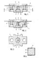
- the two leaf spring-like contact spring elements 2 and 3 are fastened, in the exemplary embodiment shown with the aid of rivets 4, the contact element 3 being designed as a leaf spring which is pretensioned in the open position (FIG. 2). It is in the standby position, i.e. before triggering, pressed by a transmission pin 5 against the contact element 2 to form a continuous current path, the transmission pin 5 being supported on a melt material insert 6, preferably made of tin, which in turn is supported on a heat transfer plate 7.
- the melting material insert 6 melts, the material flowing into the recess 10 of the insulating material housing, which recess is larger in volume, so that the transmission pin 5 is also pressed down under the action of the spring force of the contact element 3 and thus opens the current path.
- a surface protective coating 8 in the form of a copper or silver layer with a thickness of approximately 10 ⁇ m or less is applied to the melt material insert 6, which is preferably made of tin, in the exemplary embodiment shown (FIG. 4) this copper layer is covered by a further tin layer 9, so that the external appearance of the melt material insert corresponds exactly to that of an untreated and thus unprotected tin insert.
- the melt material insert 6 is a square prism, the side length a is selected so that a corresponds to the diameter of the circular recess 10, so that the recess represents the circumference for the use of the melting material and this is thus held in the simplest manner so that there is nevertheless sufficient space for the solder to flow away.
Landscapes
- Chemical & Material Sciences (AREA)
- Engineering & Computer Science (AREA)
- Combustion & Propulsion (AREA)
- Fuses (AREA)
Applications Claiming Priority (2)
| Application Number | Priority Date | Filing Date | Title |
|---|---|---|---|
| DE3711068 | 1987-04-02 | ||
| DE19873711068 DE3711068A1 (de) | 1987-04-02 | 1987-04-02 | Temperatursicherung fuer elektrische geraete |
Publications (2)
| Publication Number | Publication Date |
|---|---|
| EP0285044A2 true EP0285044A2 (fr) | 1988-10-05 |
| EP0285044A3 EP0285044A3 (fr) | 1990-07-04 |
Family
ID=6324689
Family Applications (1)
| Application Number | Title | Priority Date | Filing Date |
|---|---|---|---|
| EP88104917A Withdrawn EP0285044A3 (fr) | 1987-04-02 | 1988-03-26 | Fusible thermique pour appareils électriques |
Country Status (2)
| Country | Link |
|---|---|
| EP (1) | EP0285044A3 (fr) |
| DE (1) | DE3711068A1 (fr) |
Cited By (4)
| Publication number | Priority date | Publication date | Assignee | Title |
|---|---|---|---|---|
| FR2668295A1 (fr) * | 1990-10-18 | 1992-04-24 | Electrovac | Pastille de soudure pour protection thermique. |
| EP0640997A1 (fr) * | 1993-08-26 | 1995-03-01 | Omron Corporation | Commutateur |
| DE102005060965A1 (de) * | 2005-06-28 | 2007-01-04 | Inter Control Hermann Köhler Elektrik GmbH & Co. KG | Thermische Sicherung mit Verfahren zu ihrer Herstellung |
| WO2023073298A1 (fr) * | 2021-10-29 | 2023-05-04 | Safran Electrical & Power | Dispositif d'alimentation électrique à protection thermique |
Families Citing this family (1)
| Publication number | Priority date | Publication date | Assignee | Title |
|---|---|---|---|---|
| DE10044081A1 (de) * | 2000-09-07 | 2002-04-04 | Bosch Gmbh Robert | Überlastschutz |
Family Cites Families (9)
| Publication number | Priority date | Publication date | Assignee | Title |
|---|---|---|---|---|
| DE267828C (fr) * | ||||
| FR344670A (fr) * | 1904-07-08 | 1904-11-10 | Brev Dolter Soc D Expl Des | Fil fusible de sureté |
| US3201646A (en) * | 1960-10-03 | 1965-08-17 | Gen Electric | Ballast apparatus utilizing temperature responsive fuse |
| US3168632A (en) * | 1961-10-31 | 1965-02-02 | Advance Transformer Co | Ballast disconnect device having a coating of flux material |
| DE2339674C2 (de) * | 1973-08-04 | 1989-09-21 | Thermostat-und Schaltgerätebau GmbH & Co KG, 8730 Bad Kissingen | Temperaturregler mit Schmelzmetallsicherung |
| US4065741A (en) * | 1977-03-29 | 1977-12-27 | New Nippon Electric Co., Ltd. | Thermal fuse with a fusible temperature sensitive pellet |
| DE2826205C2 (de) * | 1978-06-15 | 1986-11-20 | Inter Control Hermann Köhler Elektrik GmbH & Co KG, 8500 Nürnberg | Temperatursicherung für elektrische Geräte |
| GB2060260A (en) * | 1979-09-28 | 1981-04-29 | Mccaughna J R | A Thermal Cut-off |
| DE2942478A1 (de) * | 1979-10-20 | 1981-04-30 | Inter Control Hermann Köhler Elektrik GmbH & Co KG, 8500 Nürnberg | Temperatur-sicherungsschalter |
-
1987
- 1987-04-02 DE DE19873711068 patent/DE3711068A1/de active Granted
-
1988
- 1988-03-26 EP EP88104917A patent/EP0285044A3/fr not_active Withdrawn
Cited By (8)
| Publication number | Priority date | Publication date | Assignee | Title |
|---|---|---|---|---|
| FR2668295A1 (fr) * | 1990-10-18 | 1992-04-24 | Electrovac | Pastille de soudure pour protection thermique. |
| US5159309A (en) * | 1990-10-18 | 1992-10-27 | Electrovac, Fabrikation Elektro-Technischer Spezialartikel Gesellschaft M.B.H. | Solder pellet |
| EP0640997A1 (fr) * | 1993-08-26 | 1995-03-01 | Omron Corporation | Commutateur |
| US5534842A (en) * | 1993-08-26 | 1996-07-09 | Omron Corporation | Circuit breaking switch with fusible element that responds to current overloads |
| DE102005060965A1 (de) * | 2005-06-28 | 2007-01-04 | Inter Control Hermann Köhler Elektrik GmbH & Co. KG | Thermische Sicherung mit Verfahren zu ihrer Herstellung |
| DE102005060965B4 (de) * | 2005-06-28 | 2007-08-16 | Inter Control Hermann Köhler Elektrik GmbH & Co. KG | Thermische Sicherung mit Verfahren zu ihrer Herstellung |
| WO2023073298A1 (fr) * | 2021-10-29 | 2023-05-04 | Safran Electrical & Power | Dispositif d'alimentation électrique à protection thermique |
| FR3128817A1 (fr) * | 2021-10-29 | 2023-05-05 | Safran Electrical & Power | Dispositif d’alimentation électrique à protection thermique |
Also Published As
| Publication number | Publication date |
|---|---|
| EP0285044A3 (fr) | 1990-07-04 |
| DE3711068A1 (de) | 1988-10-20 |
| DE3711068C2 (fr) | 1989-10-05 |
Similar Documents
| Publication | Publication Date | Title |
|---|---|---|
| DE3118943C2 (fr) | ||
| EP1821379B1 (fr) | Paratonnerre rempli de gaz doté d'un dispositif de court-circuit externe | |
| EP0935273A2 (fr) | Conducteur fusible pour cartouche à fusible | |
| DE1588425A1 (de) | Thermische Schmelzsicherung | |
| EP0285044A2 (fr) | Fusible thermique pour appareils électriques | |
| DE2233792A1 (de) | Elektrischer schalter | |
| DE2412688C3 (de) | Strombegrenzende sandgefüllte elektrische Sicherung | |
| DE1515624B1 (de) | Elektrischer Widerstand mit Schmelzsicherung | |
| DE4128558A1 (de) | Lotpille | |
| DE1588034B2 (de) | Von der umgebungstemperatur abhaengige elektrische sicherung | |
| DE2619329A1 (de) | Elektrisches bauelement fuer eine mit zeitverzoegerung arbeitende schmelzsicherung | |
| DE1233477B (de) | Traeger Schmelzeinsatz mit verdrillten Schmelzleitern | |
| DE576636C (de) | UEberlastungstraege, kurzschlusssichere Schmelzsicherungspatrone | |
| DE19851311B4 (de) | Elektrische Bruchsicherung mit Memory-Einsatz und dafür geeignete Memory-Legierungen | |
| DE3426404A1 (de) | Hochspannungs-hochleistungs-sicherung | |
| DE638021C (de) | UEberlastungstraege, kurzschlusssicher geschlossene Patrone fuer Schraubstoepselsicherungen des D-Systems | |
| EP0170186A2 (fr) | Dispositif de coupe-circuit électrique avec un conducteur fusible | |
| DE102016109923B4 (de) | Elektrische Sicherungseinrichtung mit verbesserter Auslösecharakteristik | |
| DE102019119513B4 (de) | Überspannungsschutzelement und Bauelementanordnung für ein Überspannungsschutzelement | |
| DE3620973A1 (de) | Oelbad-loeschrohrsicherungspatrone | |
| DE19846349A1 (de) | Schmelzleiter für einen elektrischen Sicherungseinsatz | |
| DE3151872A1 (de) | Elektrischer tauchbadwaermer mit fehlerstromsicherung | |
| DE9007239U1 (de) | Elektrische Sicherung | |
| EP1517348B1 (fr) | Elément fusible avec pieds de contact profilés et procédé de fabrication | |
| DE458738C (de) | Schmelzsicherung |
Legal Events
| Date | Code | Title | Description |
|---|---|---|---|
| PUAI | Public reference made under article 153(3) epc to a published international application that has entered the european phase |
Free format text: ORIGINAL CODE: 0009012 |
|
| AK | Designated contracting states |
Kind code of ref document: A2 Designated state(s): AT BE CH DE ES FR GB GR IT LI LU NL SE |
|
| PUAL | Search report despatched |
Free format text: ORIGINAL CODE: 0009013 |
|
| AK | Designated contracting states |
Kind code of ref document: A3 Designated state(s): AT BE CH DE ES FR GB GR IT LI LU NL SE |
|
| STAA | Information on the status of an ep patent application or granted ep patent |
Free format text: STATUS: THE APPLICATION IS DEEMED TO BE WITHDRAWN |
|
| 18D | Application deemed to be withdrawn |
Effective date: 19910105 |