EP0285083A2 - Résistance préréglable - Google Patents
Résistance préréglable Download PDFInfo
- Publication number
- EP0285083A2 EP0285083A2 EP88105042A EP88105042A EP0285083A2 EP 0285083 A2 EP0285083 A2 EP 0285083A2 EP 88105042 A EP88105042 A EP 88105042A EP 88105042 A EP88105042 A EP 88105042A EP 0285083 A2 EP0285083 A2 EP 0285083A2
- Authority
- EP
- European Patent Office
- Prior art keywords
- resistor
- presettable
- control input
- potential
- resistor according
- Prior art date
- Legal status (The legal status is an assumption and is not a legal conclusion. Google has not performed a legal analysis and makes no representation as to the accuracy of the status listed.)
- Withdrawn
Links
- 239000003990 capacitor Substances 0.000 claims description 5
- 230000002265 prevention Effects 0.000 abstract 1
- 238000010079 rubber tapping Methods 0.000 abstract 1
- 230000000903 blocking effect Effects 0.000 description 1
- 230000006378 damage Effects 0.000 description 1
- 230000001419 dependent effect Effects 0.000 description 1
- 238000011161 development Methods 0.000 description 1
- 230000018109 developmental process Effects 0.000 description 1
- 238000009434 installation Methods 0.000 description 1
Images
Classifications
-
- G—PHYSICS
- G05—CONTROLLING; REGULATING
- G05D—SYSTEMS FOR CONTROLLING OR REGULATING NON-ELECTRIC VARIABLES
- G05D23/00—Control of temperature
- G05D23/19—Control of temperature characterised by the use of electric means
- G05D23/20—Control of temperature characterised by the use of electric means with sensing elements having variation of electric or magnetic properties with change of temperature
- G05D23/24—Control of temperature characterised by the use of electric means with sensing elements having variation of electric or magnetic properties with change of temperature the sensing element having a resistance varying with temperature, e.g. a thermistor
-
- G—PHYSICS
- G05—CONTROLLING; REGULATING
- G05D—SYSTEMS FOR CONTROLLING OR REGULATING NON-ELECTRIC VARIABLES
- G05D23/00—Control of temperature
- G05D23/19—Control of temperature characterised by the use of electric means
- G05D23/1902—Control of temperature characterised by the use of electric means characterised by the use of a variable reference value
- G05D23/1904—Control of temperature characterised by the use of electric means characterised by the use of a variable reference value variable in time
Definitions
- the invention relates to a presettable resistor, in particular for an electronic room thermostat, according to the preamble of claim 1.
- Presettable resistors are used in electronic devices to determine a working point or an operating state.
- Mechanical and electronic versions are known, which are set by an actuator. It is disadvantageous that when a different resistance value is set, the previous setting can only be found using a memory or a corresponding scale.
- a second or further resistance value is set as required and is later to be reset to the basic setting. This application is e.g. in the case of an electronic room thermostat which, in addition to the normal setting, also offers "night reduction” and possibly “frost protection".
- the setting of these different operating states should also be able to be carried out easily and conveniently even in the case of spatially distant devices, without the need to operate the device itself.
- the invention is therefore based on the object of providing a presettable resistor which can be used to remotely choose between a further resistance value and the basic setting.
- the remotely controllable switch arrangement can be used to tap or connect the resistor to produce an additional resistor or a shunt to a sub-area of the resistor which changes the resistance value in the desired manner. After opening the switch, the basic setting is available again.
- the advantage of the invention is to be able to set several pre-installable resistors in this way at the same time by means of a common control signal. In electronic room thermostats as a preferred field of application, this can be done manually or automatically from a control center.
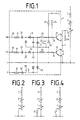
- a series circuit comprising a variable resistor 1, a permanently adjustable resistor 2 and a temperature-dependent resistor 3 is arranged between a terminal T and reference potential N.
- the total resistance of this series connection specifies the level of a control current that controls the output of a heater.
- the variable resistor 1 has a tap 5 which is connected to a first output terminal 6 of a remotely controllable switch arrangement 4.
- the remote-controllable switch arrangement 4 comprises a first electronic switch 11 as an active switch with a first output terminal 6 and a second output terminal 7 and a second electronic switch 12 with a third output terminal 8 and a fourth output terminal 9.
- the second and third output terminals 7, 8 are connected to one another, while the fourth output terminal 9 is connected to reference potential N.
- An additional resistor 10 is located between the first output terminal 6 and the second output terminal 7.
- the electronic switches designed as NPN transistors 11; 12 have control inputs 13; 14, of which a first control input 13 is connected to a first control line 29 via a resistor 25, a first rectifier circuit 15 and a series circuit comprising a series resistor 17 and a capacitor 18 and of which a second control input 14 is connected to a second control line 30 via a resistor 26 and a second rectifier 16 and a series circuit comprising a series resistor 19 and a capacitor 20.
- the first control input 13 is also connected via a resistor 23 and the second control input 14 via a resistor 24 to a positive potential + U.
- the first control line 29 ends at a terminal NA for the "night reduction" operating state and the second control line 30 at a terminal FS for the "frost protection" operating state.
- the second rectifier circuit 16 If mains potential is connected between the terminal FS and the reference potential by means of the remote switching device, the second rectifier circuit 16 generates a negative potential which blocks the transistor 12 via the control input 14. This potential also couples via the diode 21 to the other control input 13, as a result of which the transistor 11 is also blocked.
- a limiting diode 22 prevents the potential at the first control input 13 from adopting negative values which are too high and which can possibly lead to the destruction of the transistor 11. In this operating state, the connection between the terminal 5 and the reference potential N is practically interrupted, which is indicated in FIG. 4 by the open switch.
- the circuit described has the advantage that the remote switching device can simply apply mains potential to the connection terminals NA or FS and the required control voltage is generated by the rectifier circuits. Current limitation and galvanic decoupling are achieved by the capacitors 18, 20.
- the connecting lines between the remote switching device and the connection terminals NA and FS can be implemented and routed using standard domestic installation technology.
- an additional switch 27 is assigned to the first control input 13 and an additional switch 28 to the second control input 14.
- the switch 27 By closing the switch 27, the potential at the control input 13 is pulled to the reference potential N and the transistor 11 is blocked. This sets the "Night reduction” operating state.
- the switch 28 By closing the switch 28, the mains potential present at the terminal P is supplied to the second control input 14 via a series circuit comprising a resistor 31 and a capacitor 32 and a rectifier circuit 33 and to the first control input 13 via the diode 21. In this case, both transistors 11 and 12 open, as a result of which the “frost protection” operating mode is set.
Landscapes
- Physics & Mathematics (AREA)
- General Physics & Mathematics (AREA)
- Engineering & Computer Science (AREA)
- Automation & Control Theory (AREA)
- Air Conditioning Control Device (AREA)
- Thermally Actuated Switches (AREA)
Applications Claiming Priority (2)
| Application Number | Priority Date | Filing Date | Title |
|---|---|---|---|
| DE19873711102 DE3711102A1 (de) | 1987-04-02 | 1987-04-02 | Voreinstellbarer widerstand |
| DE3711102 | 1987-04-02 |
Publications (2)
| Publication Number | Publication Date |
|---|---|
| EP0285083A2 true EP0285083A2 (fr) | 1988-10-05 |
| EP0285083A3 EP0285083A3 (fr) | 1990-01-10 |
Family
ID=6324707
Family Applications (1)
| Application Number | Title | Priority Date | Filing Date |
|---|---|---|---|
| EP88105042A Withdrawn EP0285083A3 (fr) | 1987-04-02 | 1988-03-29 | Résistance préréglable |
Country Status (2)
| Country | Link |
|---|---|
| EP (1) | EP0285083A3 (fr) |
| DE (1) | DE3711102A1 (fr) |
Family Cites Families (11)
| Publication number | Priority date | Publication date | Assignee | Title |
|---|---|---|---|---|
| FR1360845A (fr) * | 1963-04-05 | 1964-05-15 | Appareil régulateur de températures | |
| FR1420079A (fr) * | 1965-01-06 | 1965-12-03 | Honeywell Inc | Potentiomètre |
| DE1922199B1 (de) * | 1969-04-30 | 1970-11-12 | Siemens Ag | Thermostat mit einem keramischen Kaltleiter als selbstregelnder Heizwiderstand |
| FR2358700A1 (fr) * | 1976-07-17 | 1978-02-10 | Vaillant Sa | Dispositif de controle pour le rechargement d'un systeme de chauffage electrique a accumulation |
| NL7909295A (nl) * | 1979-12-21 | 1981-07-16 | Holec Nv | Regelketen voor een verwarmingsinstallatie en ruimtetemperatuur afhankelijke stooklijnverlaging. |
| DE3101861C2 (de) * | 1981-01-22 | 1985-04-11 | Peter Dipl.-Ing. 4000 Düsseldorf Loewenhoff | Steuergerät für eine zum Beheizen mehrerer Räume dienende Raumheizungsanlage |
| US4411306A (en) * | 1981-05-29 | 1983-10-25 | Honeywell Inc. | Thermostat with improved temperature sensing circuit |
| CH654678A5 (de) * | 1981-11-30 | 1986-02-28 | Landis & Gyr Ag | Einrichtung zur regelung des energieflusses zu einem gebaeude bzw. zur regelung der temperatur in diesem gebaeude. |
| JPS59104038A (ja) * | 1982-12-06 | 1984-06-15 | Hitachi Ltd | 空気調和機の制御方式 |
| NO152890C (no) * | 1983-08-15 | 1985-12-04 | Siemens As | Anordning for styring av termostater i oppvarmingsenheter, saerlig varmeovner. |
| CH665705A5 (de) * | 1984-11-22 | 1988-05-31 | Landis & Gyr Ag | Einrichtung zur beeinflussung eines regelgeraetes einer heizungsanlage von einem raumgeraet aus. |
-
1987
- 1987-04-02 DE DE19873711102 patent/DE3711102A1/de not_active Withdrawn
-
1988
- 1988-03-29 EP EP88105042A patent/EP0285083A3/fr not_active Withdrawn
Also Published As
| Publication number | Publication date |
|---|---|
| DE3711102A1 (de) | 1988-10-13 |
| EP0285083A3 (fr) | 1990-01-10 |
Similar Documents
| Publication | Publication Date | Title |
|---|---|---|
| EP0423885B1 (fr) | Dispositif d'alimentation avec limitation du courant d'appel | |
| EP0572706B1 (fr) | Circuit de commande pour un transistor à effet de champ de puissance dont le source et connectée à une charge | |
| EP0314681B1 (fr) | Etage final de circuit a pont | |
| EP0131146B1 (fr) | Appareil de commutation électronique, fonctionnant de préférence sans contact | |
| EP0986039B1 (fr) | Dispositif pour l'alimentation d'un émetteur d'une boucle de courant | |
| DE2710049C2 (de) | Ultraschall-Zahnbehandlungsgerät | |
| DE3929026A1 (de) | Ansteuerschaltung fuer eine getaktete last in einem fahrzeug | |
| EP0771492B1 (fr) | Amplificateur de reglage pour moduler une source basse tension a haute impedance | |
| EP0098460B1 (fr) | Dispositif de régulation pour organe électrique de manoeuvre | |
| EP1226594B1 (fr) | Ensemble circuit electrique servant a convertir une tension d'entree | |
| EP0285083A2 (fr) | Résistance préréglable | |
| DE4231060A1 (de) | Verfahren zum elektronischen Dimmen und Dimmer zur Durchführung des Verfahrens | |
| DE2715609A1 (de) | Fenster-diskriminatorschaltung | |
| DE4428115A1 (de) | Steuergerät mit einer Schaltungsanordnung zum Schutz des Steuergerätes bei Unterbrechung der Steuergerätemasse | |
| DE3635514A1 (de) | Schaltungsanordnung zur regelung des speisestroms fuer ein fernmeldetechnisches endgeraet | |
| DE2100929A1 (de) | Steuerschaltung zur Versorgung eines induktiven Verbrauchers | |
| DE2450688A1 (de) | Elektronische aufladesteuereinrichtung fuer elektrische speicherheizgeraete | |
| DE2009039A1 (de) | Schaltung mit Überstromschutz | |
| DE19833968A1 (de) | Integrierte Reglervorrichtung | |
| CH678127A5 (fr) | ||
| DE1638049C3 (de) | Schaltungsanordnung für einen elektronischen Schalter | |
| DE69410211T2 (de) | Schnittstelle für durch Mirkoprozessoren und/oder Mikrocontroller gesteuerte Geräte | |
| DE2504923A1 (de) | Elektronische ansteuerungsschaltung fuer anzeigelampen | |
| EP0755117A1 (fr) | Procédé pour commander un circuit de charge | |
| DE1952011C3 (de) | Schaltungsanordnung zur Leistungsverstärkung von Impulsen, insbesondere für elektromagnetisch gesteuerte Einrichtungen |
Legal Events
| Date | Code | Title | Description |
|---|---|---|---|
| PUAI | Public reference made under article 153(3) epc to a published international application that has entered the european phase |
Free format text: ORIGINAL CODE: 0009012 |
|
| AK | Designated contracting states |
Kind code of ref document: A2 Designated state(s): AT BE CH DE ES FR GB GR IT LI LU NL SE |
|
| PUAL | Search report despatched |
Free format text: ORIGINAL CODE: 0009013 |
|
| AK | Designated contracting states |
Kind code of ref document: A3 Designated state(s): AT BE CH DE ES FR GB GR IT LI LU NL SE |
|
| 17P | Request for examination filed |
Effective date: 19900310 |
|
| 17Q | First examination report despatched |
Effective date: 19920511 |
|
| STAA | Information on the status of an ep patent application or granted ep patent |
Free format text: STATUS: THE APPLICATION IS DEEMED TO BE WITHDRAWN |
|
| 18D | Application deemed to be withdrawn |
Effective date: 19920922 |