EP0285217A1 - Einrichtung zum Verteilen eines Mediums auf einem Substrat, Verfahren zum Beschichten des Substrats mit dem Medium, mittels dieser Einrichtung beschichtetes Substrat - Google Patents
Einrichtung zum Verteilen eines Mediums auf einem Substrat, Verfahren zum Beschichten des Substrats mit dem Medium, mittels dieser Einrichtung beschichtetes Substrat Download PDFInfo
- Publication number
- EP0285217A1 EP0285217A1 EP88200558A EP88200558A EP0285217A1 EP 0285217 A1 EP0285217 A1 EP 0285217A1 EP 88200558 A EP88200558 A EP 88200558A EP 88200558 A EP88200558 A EP 88200558A EP 0285217 A1 EP0285217 A1 EP 0285217A1
- Authority
- EP
- European Patent Office
- Prior art keywords
- medium
- slit
- substrate
- distributing
- coating
- Prior art date
- Legal status (The legal status is an assumption and is not a legal conclusion. Google has not performed a legal analysis and makes no representation as to the accuracy of the status listed.)
- Granted
Links
Images




Classifications
-
- B—PERFORMING OPERATIONS; TRANSPORTING
- B41—PRINTING; LINING MACHINES; TYPEWRITERS; STAMPS
- B41F—PRINTING MACHINES OR PRESSES
- B41F15/00—Screen printers
- B41F15/14—Details
- B41F15/44—Squeegees or doctors
-
- B—PERFORMING OPERATIONS; TRANSPORTING
- B41—PRINTING; LINING MACHINES; TYPEWRITERS; STAMPS
- B41F—PRINTING MACHINES OR PRESSES
- B41F15/00—Screen printers
- B41F15/14—Details
- B41F15/40—Inking units
- B41F15/42—Inking units comprising squeegees or doctors
Definitions
- the invention relates to a device for uniformly distributing a viscous medium in the width direction of a web-like substrate moving predominantly perpendicularly to the device, at least comprising: medium supply means; at least one medium-distributing space and an outflow slit adjoining the distributing space.
- - Slit length this is the dimension of the outflow slit measured along the length of the medium-distributing device.
- - Slit wall height this is the dimension, viewed in the flow direction of the medium, of the walls delimiting the outflow slit with the smallest dimension in a certain position along the length of the slit.
- - Slit width this is the distance between the walls delimiting the outflow slit in a certain position along the length of the slit.
- the device has a rod-shaped exterior and the central axis of said device is generally oriented predominantly perpendicular to the direction of movement of the substrate, to which the medium is to be applied.
- the device described comprises two outflow slits and is intended for uniformly distributing the medium in the width direction of said moving substrate; yet, such a uniform distribution of medium in the width direction of the substrate is not completely achieved in many cases.
- Slit wall height and slit width will normally be constant over the length of the slit.
- one or more of the sliding pieces used can very advantageously be provided with lateral bulkheads extending to the upstream side of the substrate and oriented perpendicular to the substrate.
- the medium-distributing device is very advantageously used in cases in which a foam-like medium has to be applied to a moving substrate using a rotary screen printing stencil, known per se, the medium discharge opening of the device resting against the inner wall of said stencil.
- a rotary screen printing stencil of this type may be an unpatterned stencil for those cases in which the foam is to be applied in an even coating layer to a substrate, for example a textile web.
- the stencil used may also be provided with a pattern for the case that the foam is to be applied so as to form a pattern.
- each viscous medium can successfully be processed using a distributing device according to the invention.
- Figure 1 shows a distributing device according to the present state of the art 1 composed of a body 2 with medium-distributing spaces 3 and 4, slit-shaped outflow surfaces 5 and 6, as well as a conventional medium-collecting space 7 and a medium discharge opening 8. Adjustment of the dimension of the slit-shaped outflow surface 5 and 6 is achieved by means of adjustable strips 9 and 10.
- the medium-distributing device 1 is located at the inner side of a stencil 11, the medium discharge opening 8 being in contact with the inner wall of said stencil 11. The discharged medium passes through the perforations in the stencil and in this way arrives at the surface of the moving substrate 12.
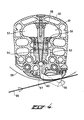
- Figure 2A and 2B show a distributing devices according to the invention, according to a first embodiment in which the device 20 with a body 21 comprises distributing spaces 22 and 23.
- the medium can flow into slit-shaped spaces 28 and 29 in the downstream direction, these spaces ending in outflow strips 24 and 25.
- the slits are formed by plates 34 and 35 which are fixed by spacers and fastening means 30 and 31, respectively, on a plate, which in this case is arranged centrally, extending over the length of the distributing device.
- the plates 34 and 35 are in tight contact with the inner wall of the device 20 on one longitudinal side.
- the slit wall height is 45 mm, while the slit width is 0.5 mm, the quotient between the two parameters therefore being 90.
- additional adjustment may take place by either varying, while maintaining a ratio of at least 25 between slit wall height and slit width, the slit width according to a particular pattern over the length of the device, with the slit wall height being fixed, or varying the slit wall height according to a particular pattern, with the slit width being fixed, as mentioned before.
- Figure 3 shows another embodiment of the device; the device 40 comprises medium-distributing spaces 44 and 45, a slit-shaped space 46 of large length, the medium flowing from distributing space 42 in the direction shown by arrow 44 to space 43 and from there, as shown by arrow 45, arriving in the slit-shaped space 46. 47 indicates a spacer intended for maintaining the width of the slit-shaped space at the correctly adjusted value.
- Figure 5 shows the situation in which a substrate 72 is passed over a roll 71, a doctor blade 74 being arranged at short angular distance in front of the perpendicular plane through their axis of the roll.
- a medium-distributing device 60 is arranged with distributing spaces 63 and 64 to which medium supply lines 61 and 62 connect and in which the distributing spaces 63 and 64 are arranged, as is shown in Figure 4 described above; the slits formed connect to a collecting space 67 which ends in medium discharge opening 75.
- a sliding piece 68 to which a lateral partition 70 is attached, is received in the collecting space.
- connection between the rod- shaped section 68 and the lateral partition 70 is formed by a strip-shaped part received in the collecting space 67.
- Figure 6 shows two graphs in which the amount, in grams, of medium, for example foam medium, applied per minute is given in the vertical direction and the location along the longitudinal direction of the distributing device is given in the horizontal direction.
- Figure 6A shows the result for a device according to the present state of the art, incorporating two slits complementing each other, while Figure 6B shows the results obtaining using a device according to the invention. It is evident in Figure 6A that the application achieved is not uniform; on the other hand, it can be seen in Figure 6B that an extremely uniform application across the longitudinal direction of the device is achieved by means of a distributing device according to the invention.
- the medium outflow surface will in many cases be followed by a medium collecting space in which a slit-shaped medium discharge opening is located.
- a medium collecting space is not necessary, however, in every case, said medium discharge opening can in certain cases be formed by the medium outflow surface, in other words the outflow slit of the slit-shaped space.
Landscapes
- Engineering & Computer Science (AREA)
- Mechanical Engineering (AREA)
- Coating Apparatus (AREA)
- Screen Printers (AREA)
- Polymers With Sulfur, Phosphorus Or Metals In The Main Chain (AREA)
- Manufacturing Of Printed Wiring (AREA)
- Manufacturing Optical Record Carriers (AREA)
- Application Of Or Painting With Fluid Materials (AREA)
Priority Applications (1)
| Application Number | Priority Date | Filing Date | Title |
|---|---|---|---|
| AT88200558T ATE68412T1 (de) | 1987-03-31 | 1988-03-24 | Einrichtung zum verteilen eines mediums auf einem substrat, verfahren zum beschichten des substrats mit dem medium, mittels dieser einrichtung beschichtetes substrat. |
Applications Claiming Priority (2)
| Application Number | Priority Date | Filing Date | Title |
|---|---|---|---|
| NL8700754 | 1987-03-31 | ||
| NL8700754A NL8700754A (nl) | 1987-03-31 | 1987-03-31 | Inrichting voor het verdelen van een medium op een substraat; werkwijze voor het met een medium bekleden van een substraat en met behulp van de inrichting bekleed substraat. |
Publications (2)
| Publication Number | Publication Date |
|---|---|
| EP0285217A1 true EP0285217A1 (de) | 1988-10-05 |
| EP0285217B1 EP0285217B1 (de) | 1991-10-16 |
Family
ID=19849787
Family Applications (1)
| Application Number | Title | Priority Date | Filing Date |
|---|---|---|---|
| EP88200558A Expired - Lifetime EP0285217B1 (de) | 1987-03-31 | 1988-03-24 | Einrichtung zum Verteilen eines Mediums auf einem Substrat, Verfahren zum Beschichten des Substrats mit dem Medium, mittels dieser Einrichtung beschichtetes Substrat |
Country Status (7)
| Country | Link |
|---|---|
| EP (1) | EP0285217B1 (de) |
| JP (1) | JPS63270575A (de) |
| AT (1) | ATE68412T1 (de) |
| DE (1) | DE3865483D1 (de) |
| ES (1) | ES2027371T3 (de) |
| IN (1) | IN170987B (de) |
| NL (1) | NL8700754A (de) |
Cited By (3)
| Publication number | Priority date | Publication date | Assignee | Title |
|---|---|---|---|---|
| EP0392625A1 (de) * | 1989-04-12 | 1990-10-17 | Stork X-Cel B.V. | Vorrichtung für Schön- und Wiederbeschichtung und Verfahren zum Beschichten einer Materialbahn |
| NL1005308C2 (nl) * | 1997-02-18 | 1998-08-20 | Stork Brabant Bv | Rakel met een vast dragend deel. |
| US6286422B1 (en) * | 1994-12-27 | 2001-09-11 | Visteon Global Tech., Inc. | Method and apparatus for dispensing viscous material |
Families Citing this family (1)
| Publication number | Priority date | Publication date | Assignee | Title |
|---|---|---|---|---|
| DE102008025927A1 (de) * | 2008-05-29 | 2009-12-24 | Zyrus Beteiligungsgesellschaft Mbh & Co. Patente I Kg | Rotationsdruckmaschine |
Citations (3)
| Publication number | Priority date | Publication date | Assignee | Title |
|---|---|---|---|---|
| US3155034A (en) * | 1961-11-01 | 1964-11-03 | Rineglas Inc | Silk screen printing press |
| DE2450309A1 (de) * | 1974-10-23 | 1976-04-29 | Mitter & Co | Vorrichtung zur begrenzung des farbtuempels vor einer im inneren einer siebdruckschablone angeordneten auftragsrolle |
| DE3200171A1 (de) * | 1982-01-07 | 1983-07-14 | Mitter, Mathias, 4815 Schloss Holte | Vorrichtung zum auftragen von fluessigen, pastoesen oder verschaeumten medien auf eine ware, vorzugsweise mittels einer schlitzrakel |
Family Cites Families (3)
| Publication number | Priority date | Publication date | Assignee | Title |
|---|---|---|---|---|
| JPS547306A (en) * | 1977-06-20 | 1979-01-20 | Sony Corp | Optical video disc reproducer |
| NL8201505A (nl) * | 1982-04-08 | 1983-11-01 | Stork Brabant Bv | Verdeelsysteem voor een visqueuze substantie. |
| JPS626968A (ja) * | 1985-07-01 | 1987-01-13 | 株式会社 小南鋳造鉄工所 | 毛布等のピリング毛玉除去方法並びにその装置 |
-
1987
- 1987-03-31 NL NL8700754A patent/NL8700754A/nl not_active Application Discontinuation
-
1988
- 1988-03-24 ES ES198888200558T patent/ES2027371T3/es not_active Expired - Lifetime
- 1988-03-24 AT AT88200558T patent/ATE68412T1/de not_active IP Right Cessation
- 1988-03-24 DE DE8888200558T patent/DE3865483D1/de not_active Expired - Fee Related
- 1988-03-24 EP EP88200558A patent/EP0285217B1/de not_active Expired - Lifetime
- 1988-03-31 JP JP63081143A patent/JPS63270575A/ja active Granted
- 1988-04-07 IN IN229/MAS/88A patent/IN170987B/en unknown
Patent Citations (3)
| Publication number | Priority date | Publication date | Assignee | Title |
|---|---|---|---|---|
| US3155034A (en) * | 1961-11-01 | 1964-11-03 | Rineglas Inc | Silk screen printing press |
| DE2450309A1 (de) * | 1974-10-23 | 1976-04-29 | Mitter & Co | Vorrichtung zur begrenzung des farbtuempels vor einer im inneren einer siebdruckschablone angeordneten auftragsrolle |
| DE3200171A1 (de) * | 1982-01-07 | 1983-07-14 | Mitter, Mathias, 4815 Schloss Holte | Vorrichtung zum auftragen von fluessigen, pastoesen oder verschaeumten medien auf eine ware, vorzugsweise mittels einer schlitzrakel |
Cited By (5)
| Publication number | Priority date | Publication date | Assignee | Title |
|---|---|---|---|---|
| EP0392625A1 (de) * | 1989-04-12 | 1990-10-17 | Stork X-Cel B.V. | Vorrichtung für Schön- und Wiederbeschichtung und Verfahren zum Beschichten einer Materialbahn |
| US6286422B1 (en) * | 1994-12-27 | 2001-09-11 | Visteon Global Tech., Inc. | Method and apparatus for dispensing viscous material |
| NL1005308C2 (nl) * | 1997-02-18 | 1998-08-20 | Stork Brabant Bv | Rakel met een vast dragend deel. |
| EP0860275A1 (de) * | 1997-02-18 | 1998-08-26 | Stork Brabant B.V. | Rakel mit festem Trägerteil |
| US6101936A (en) * | 1997-02-18 | 2000-08-15 | Stork Brabant B.V. | Squeegee with a fixed supporting part |
Also Published As
| Publication number | Publication date |
|---|---|
| JPH0567344B2 (de) | 1993-09-24 |
| IN170987B (de) | 1992-06-27 |
| ES2027371T3 (es) | 1992-06-01 |
| EP0285217B1 (de) | 1991-10-16 |
| NL8700754A (nl) | 1988-10-17 |
| ATE68412T1 (de) | 1991-11-15 |
| JPS63270575A (ja) | 1988-11-08 |
| DE3865483D1 (de) | 1991-11-21 |
Similar Documents
| Publication | Publication Date | Title |
|---|---|---|
| FI60420B (fi) | Foerfarande och anordning foer att reglera tjockleken av en bana | |
| US3272176A (en) | Air knife | |
| EP0151518B1 (de) | Verstellbares Luftmesser | |
| DE3927627A1 (de) | Verfahren und vorrichtung zum trocknen einer auf einem bewegten traegermaterial aufgebrachten fluessigkeitsschicht | |
| US4697542A (en) | Adjustable nozzle for coating equipment | |
| JP2788207B2 (ja) | フィルム浮揚方向転換装置 | |
| EP0285217A1 (de) | Einrichtung zum Verteilen eines Mediums auf einem Substrat, Verfahren zum Beschichten des Substrats mit dem Medium, mittels dieser Einrichtung beschichtetes Substrat | |
| US3812598A (en) | Apparatus for drying damp web material | |
| JP2821832B2 (ja) | ホットメルト接着剤塗布装置 | |
| US3599341A (en) | Method and apparatus for drying a web | |
| EP4126391B1 (de) | Schlitzdüsenbeschichtung mit konkaver düsenlippe über verformbarer stützwalze | |
| US4591133A (en) | Cooling apparatus for thick steel plate | |
| US4510863A (en) | System adapted to distribute a viscous substance | |
| JPH07171475A (ja) | ドクタロッドのための保持装置 | |
| US20050046089A1 (en) | Systems and methods for air embossing utilizing improved air lances | |
| US6935229B2 (en) | Systems and methods for stabilizing the rotation of embossing stencils used for air embossing fabrics | |
| EP0435909B1 (de) | Lufttragende mittenführung und verfahren | |
| JP2009202141A (ja) | スリットダイ及びスリットダイコータ | |
| EP0392625B1 (de) | Vorrichtung für Schön- und Wiederbeschichtung und Verfahren zum Beschichten einer Materialbahn | |
| US4417540A (en) | Coating apparatus with air-nozzle arrangement | |
| JP4195143B2 (ja) | 空気浮揚のための方法及び装置 | |
| EP0548419A1 (de) | Pneumatische Umlenkvorrichtung | |
| KR940006493B1 (ko) | 스트립 냉각 방법 및 장치 | |
| JP2992812B2 (ja) | ホットメルト接着剤塗布装置およびホットメルト接着剤塗布方法 | |
| JPH07185434A (ja) | 塗布装置 |
Legal Events
| Date | Code | Title | Description |
|---|---|---|---|
| PUAI | Public reference made under article 153(3) epc to a published international application that has entered the european phase |
Free format text: ORIGINAL CODE: 0009012 |
|
| AK | Designated contracting states |
Kind code of ref document: A1 Designated state(s): AT CH DE ES FR GB IT LI NL |
|
| 17P | Request for examination filed |
Effective date: 19881018 |
|
| 17Q | First examination report despatched |
Effective date: 19900502 |
|
| GRAA | (expected) grant |
Free format text: ORIGINAL CODE: 0009210 |
|
| ITF | It: translation for a ep patent filed | ||
| AK | Designated contracting states |
Kind code of ref document: B1 Designated state(s): AT CH DE ES FR GB IT LI NL |
|
| PG25 | Lapsed in a contracting state [announced via postgrant information from national office to epo] |
Ref country code: LI Effective date: 19911016 Ref country code: CH Effective date: 19911016 |
|
| REF | Corresponds to: |
Ref document number: 68412 Country of ref document: AT Date of ref document: 19911115 Kind code of ref document: T |
|
| ET | Fr: translation filed | ||
| REF | Corresponds to: |
Ref document number: 3865483 Country of ref document: DE Date of ref document: 19911121 |
|
| REG | Reference to a national code |
Ref country code: CH Ref legal event code: PL |
|
| REG | Reference to a national code |
Ref country code: ES Ref legal event code: FG2A Ref document number: 2027371 Country of ref document: ES Kind code of ref document: T3 |
|
| PLBE | No opposition filed within time limit |
Free format text: ORIGINAL CODE: 0009261 |
|
| STAA | Information on the status of an ep patent application or granted ep patent |
Free format text: STATUS: NO OPPOSITION FILED WITHIN TIME LIMIT |
|
| 26N | No opposition filed | ||
| PGFP | Annual fee paid to national office [announced via postgrant information from national office to epo] |
Ref country code: GB Payment date: 20000307 Year of fee payment: 13 Ref country code: FR Payment date: 20000307 Year of fee payment: 13 |
|
| PGFP | Annual fee paid to national office [announced via postgrant information from national office to epo] |
Ref country code: ES Payment date: 20000309 Year of fee payment: 13 Ref country code: AT Payment date: 20000309 Year of fee payment: 13 |
|
| PGFP | Annual fee paid to national office [announced via postgrant information from national office to epo] |
Ref country code: NL Payment date: 20000331 Year of fee payment: 13 |
|
| PGFP | Annual fee paid to national office [announced via postgrant information from national office to epo] |
Ref country code: DE Payment date: 20000425 Year of fee payment: 13 |
|
| PG25 | Lapsed in a contracting state [announced via postgrant information from national office to epo] |
Ref country code: GB Free format text: LAPSE BECAUSE OF NON-PAYMENT OF DUE FEES Effective date: 20010324 Ref country code: AT Free format text: LAPSE BECAUSE OF NON-PAYMENT OF DUE FEES Effective date: 20010324 |
|
| PG25 | Lapsed in a contracting state [announced via postgrant information from national office to epo] |
Ref country code: ES Free format text: LAPSE BECAUSE OF NON-PAYMENT OF DUE FEES Effective date: 20010326 |
|
| PG25 | Lapsed in a contracting state [announced via postgrant information from national office to epo] |
Ref country code: NL Free format text: LAPSE BECAUSE OF NON-PAYMENT OF DUE FEES Effective date: 20011001 |
|
| GBPC | Gb: european patent ceased through non-payment of renewal fee |
Effective date: 20010324 |
|
| PG25 | Lapsed in a contracting state [announced via postgrant information from national office to epo] |
Ref country code: FR Free format text: LAPSE BECAUSE OF NON-PAYMENT OF DUE FEES Effective date: 20011130 |
|
| NLV4 | Nl: lapsed or anulled due to non-payment of the annual fee |
Effective date: 20011001 |
|
| REG | Reference to a national code |
Ref country code: FR Ref legal event code: ST |
|
| PG25 | Lapsed in a contracting state [announced via postgrant information from national office to epo] |
Ref country code: DE Free format text: LAPSE BECAUSE OF NON-PAYMENT OF DUE FEES Effective date: 20020101 |
|
| REG | Reference to a national code |
Ref country code: ES Ref legal event code: FD2A Effective date: 20030203 |
|
| PG25 | Lapsed in a contracting state [announced via postgrant information from national office to epo] |
Ref country code: IT Free format text: LAPSE BECAUSE OF NON-PAYMENT OF DUE FEES;WARNING: LAPSES OF ITALIAN PATENTS WITH EFFECTIVE DATE BEFORE 2007 MAY HAVE OCCURRED AT ANY TIME BEFORE 2007. THE CORRECT EFFECTIVE DATE MAY BE DIFFERENT FROM THE ONE RECORDED. Effective date: 20050324 |