EP0285250A2 - Dispositif de visualisation de données de traitement au moyen d'éléments d'image sur un tube à rayon cathodique - Google Patents
Dispositif de visualisation de données de traitement au moyen d'éléments d'image sur un tube à rayon cathodique Download PDFInfo
- Publication number
- EP0285250A2 EP0285250A2 EP88301575A EP88301575A EP0285250A2 EP 0285250 A2 EP0285250 A2 EP 0285250A2 EP 88301575 A EP88301575 A EP 88301575A EP 88301575 A EP88301575 A EP 88301575A EP 0285250 A2 EP0285250 A2 EP 0285250A2
- Authority
- EP
- European Patent Office
- Prior art keywords
- signal
- circuit
- control
- arrangement according
- operable
- Prior art date
- Legal status (The legal status is an assumption and is not a legal conclusion. Google has not performed a legal analysis and makes no representation as to the accuracy of the status listed.)
- Withdrawn
Links
Images


Classifications
-
- G—PHYSICS
- G09—EDUCATION; CRYPTOGRAPHY; DISPLAY; ADVERTISING; SEALS
- G09G—ARRANGEMENTS OR CIRCUITS FOR CONTROL OF INDICATING DEVICES USING STATIC MEANS TO PRESENT VARIABLE INFORMATION
- G09G1/00—Control arrangements or circuits, of interest only in connection with cathode-ray tube indicators; General aspects or details, e.g. selection emphasis on particular characters, dashed line or dotted line generation; Preprocessing of data
- G09G1/06—Control arrangements or circuits, of interest only in connection with cathode-ray tube indicators; General aspects or details, e.g. selection emphasis on particular characters, dashed line or dotted line generation; Preprocessing of data using single beam tubes, e.g. three-dimensional or perspective representation, rotation or translation of display pattern, hidden lines, shadows
- G09G1/14—Control arrangements or circuits, of interest only in connection with cathode-ray tube indicators; General aspects or details, e.g. selection emphasis on particular characters, dashed line or dotted line generation; Preprocessing of data using single beam tubes, e.g. three-dimensional or perspective representation, rotation or translation of display pattern, hidden lines, shadows the beam tracing a pattern independent of the information to be displayed, this latter determining the parts of the pattern rendered respectively visible and invisible
- G09G1/16—Control arrangements or circuits, of interest only in connection with cathode-ray tube indicators; General aspects or details, e.g. selection emphasis on particular characters, dashed line or dotted line generation; Preprocessing of data using single beam tubes, e.g. three-dimensional or perspective representation, rotation or translation of display pattern, hidden lines, shadows the beam tracing a pattern independent of the information to be displayed, this latter determining the parts of the pattern rendered respectively visible and invisible the pattern of rectangular co-ordinates extending over the whole area of the screen, i.e. television type raster
- G09G1/165—Details of a display terminal using a CRT, the details relating to the control arrangement of the display terminal and to the interfaces thereto
- G09G1/167—Details of the interface to the display terminal specific for a CRT
-
- G—PHYSICS
- G09—EDUCATION; CRYPTOGRAPHY; DISPLAY; ADVERTISING; SEALS
- G09G—ARRANGEMENTS OR CIRCUITS FOR CONTROL OF INDICATING DEVICES USING STATIC MEANS TO PRESENT VARIABLE INFORMATION
- G09G1/00—Control arrangements or circuits, of interest only in connection with cathode-ray tube indicators; General aspects or details, e.g. selection emphasis on particular characters, dashed line or dotted line generation; Preprocessing of data
- G09G1/04—Deflection circuits ; Constructional details not otherwise provided for
-
- G—PHYSICS
- G09—EDUCATION; CRYPTOGRAPHY; DISPLAY; ADVERTISING; SEALS
- G09G—ARRANGEMENTS OR CIRCUITS FOR CONTROL OF INDICATING DEVICES USING STATIC MEANS TO PRESENT VARIABLE INFORMATION
- G09G1/00—Control arrangements or circuits, of interest only in connection with cathode-ray tube indicators; General aspects or details, e.g. selection emphasis on particular characters, dashed line or dotted line generation; Preprocessing of data
- G09G1/06—Control arrangements or circuits, of interest only in connection with cathode-ray tube indicators; General aspects or details, e.g. selection emphasis on particular characters, dashed line or dotted line generation; Preprocessing of data using single beam tubes, e.g. three-dimensional or perspective representation, rotation or translation of display pattern, hidden lines, shadows
- G09G1/14—Control arrangements or circuits, of interest only in connection with cathode-ray tube indicators; General aspects or details, e.g. selection emphasis on particular characters, dashed line or dotted line generation; Preprocessing of data using single beam tubes, e.g. three-dimensional or perspective representation, rotation or translation of display pattern, hidden lines, shadows the beam tracing a pattern independent of the information to be displayed, this latter determining the parts of the pattern rendered respectively visible and invisible
- G09G1/16—Control arrangements or circuits, of interest only in connection with cathode-ray tube indicators; General aspects or details, e.g. selection emphasis on particular characters, dashed line or dotted line generation; Preprocessing of data using single beam tubes, e.g. three-dimensional or perspective representation, rotation or translation of display pattern, hidden lines, shadows the beam tracing a pattern independent of the information to be displayed, this latter determining the parts of the pattern rendered respectively visible and invisible the pattern of rectangular co-ordinates extending over the whole area of the screen, i.e. television type raster
-
- G—PHYSICS
- G09—EDUCATION; CRYPTOGRAPHY; DISPLAY; ADVERTISING; SEALS
- G09G—ARRANGEMENTS OR CIRCUITS FOR CONTROL OF INDICATING DEVICES USING STATIC MEANS TO PRESENT VARIABLE INFORMATION
- G09G5/00—Control arrangements or circuits for visual indicators common to cathode-ray tube indicators and other visual indicators
- G09G5/02—Control arrangements or circuits for visual indicators common to cathode-ray tube indicators and other visual indicators characterised by the way in which colour is displayed
- G09G5/028—Circuits for converting colour display signals into monochrome display signals
Definitions
- the present invention relates to an arrangement for the display of processing data by means of pixels on a cathode ray tube of the type defined in the introductory portion of claim 1.
- the signal for control of the video display unit is defined by a plurality of logic signals generated by the video control.
- the logic signals generally comprise the signals of such colours, aluminance control signal and a group of signals for defining, in dependence on the degree of resolution or display mode, horizontal and vertical synchronisation of deflection of the electron beam over the screen of the video.
- the control for the VDU which is disposed in the computer, is interfaced with the circuit for deflection control and control of the electron beam, which is disposed in the VDU, by means of a bus which carries in parallel mode the individual signals for defining the pixel.
- a bus which carries in parallel mode the individual signals for defining the pixel.
- the object of the present invention is to provide a display arrangement in which the connection between the control unit and the video control circuit is of the utmost simplicity and reliability in operation and is economical to produce. That problem is solved by the display arrangement defined in claim 1.
- reference numeral 10 generally indicates the usual mother board of a personal computer, on which is disposed the central processing unit (CPU) together with the working memory (RAM) and the read only memory (ROM).
- the mother board 10 is normally connected by means of a bus 11 to the boards of the circuits for controlling a series of input and output peripheral units.
- a board 12 which carries the circuit for controlling the usual VDU 13.
- the control 12 comprises one or more interfaces 14, to each of which a corresponding VDU 13 can be connected by means of a cable 15.
- the VDU 13 comprises a cathode ray tube 16 and a control circuit 17 which is operable to generate the control signals and the signals for deflection of the beam of the tube 16.
- control 12 comprises buffers for the data and the images to be displayed, a video refresh memory, a ROM for generating characters, which can be addressed by means of the code of the characters, a table for selection of the base colours and a cathode ray tube control circuit (CRTC) capable of sequentially generating the signals for defining each point to be displayed on the screen (pixel).
- a pixel is normally defined by a plurality of logic circuits of which at least one is provided for defining the brightness of the pixel while generally speaking three separate logic signals are generated for defining the colour of the pixel.
- the control 12 further comprises means operable to generate two logic signals for horizontal and vertical synchronising of the emission of the signals of the pixel, with scanning of the tube.
- the signals of the pixel and the synchronising signals are normally transmitted in parallel mode from the interface 14 to the circuit 17 by means of the above-mentioned cable 15.
- the CRT 16 may be of the colour or monochromatic type.
- the logic signals in respect of the pixel individually control the electron beams of the tube 15 of the associated colours.
- the logic signals are combined to generate a scale of grey pixels corresponding to the combinations of the base colours.
- control 12 comprises a composer circuit 19 (see Figure 2) which is capable of composing the logic signals which define the pixel and the synchronising signals, as a single composite analog control signal, for which purpose the circuit 19 essentially comprises a digital-analog (D/A) converter.
- the composite signal is thus transmitted to a VDU 18 comprising a simplified video control circuit 20 (see Figure 1), by means of a cable 21 formed by a single conductor, and a monochromatic CRT
- the composite signal is emitted by way of an interface 22 of telephone type, that is to say a jack into which can be fitted a phone plug 23 connected to the end of the cable 21.
- the video control circuit 20 is capable of separating a synchronising signal from the composite signal and providing for direct control of the monochromatic CRT 24 on the basis of the composite signal which is suitably amplified.
- the control 12 is however provided with the parallel interface 14 which can be used for conventional connection to a colour VDU 13.
- the circuit 20 (see Figure 2) essentially comprises a stabilised power supplier 25 which is capable of supplying the usual high voltage transformer 26 required to supply the CRT 24.
- the circuit 20 further comprises a horizontal deflection circuit 27 which is capable of performing all the functions necessary to transform a horizontal synchronising signal H in such a way as to cause a horizontal deflection yoke 43 to generate a power signal for producing the respective horizontal deflection of the electron beam of the CRT 24.
- the circuit 27 may be formed by the integrated circuit TDA 2593 marketed by Thomson-CSF Components.
- the circuit 27 is also operable to generate at the end of each scanning line a signal P which controls a vertical deflection circuit 28.
- the circuit 28 is operable to perform all the functions necessary to transform that signal in such a way as to cause a vertical deflection yoke 44 to generate a corresponding power signal to provide for vertical deflection of the electron beam of the CRT 24.
- the circuit 28 may be formed for example by the integrated circuit TDA 1170 marketed by Thomson-CSF Components.
- the circuit 20 comprises a circuit 29 which is capable of receiving the composite signal by way of the cable 21 and separating the synchronising signal therefrom in such a way as to control the horizontal deflection circuit 27.
- the latter in turn, by way of the signal P, controls both the vertical deflection circuit 28 and a mode selection circuit 30.
- the circuit 30 is capable of defining the format, that is to say the vertical resolution and thus the number of lines of pixels on the display 24.
- the system provides for the CRT 24 a display mode in accordance with a first format consisting of 640 x 400 pixels, or in accordance with another format consisting of 640 x 350 pixels.
- the mode selection circuit 30 is also connected to a circuit 31 for regulating the frame size.
- the single video control signal which is separated from the synchronising signal is now passed to a video signal amplifier and regulator 32 which can be connected to manual controls 33 by means of which the user can adjust the brightness and the contrast of the pixels displayed, in known fashion.
- the output of the amplifier 32 is applied to a final video signal amplifier 34 which is connected to the cathode 35 of the CRT 24.
- the video control 12 produces three logic signals S0, S1 and S2 which are representative of the three fundamental colours for a colour VDU and which are representative of the corresponding grey tones for a monochromatic VDU, the three signals S0, S1 and S2 defining eight different grey levels in binary code.
- the three signals S0, S1 and S2 are applied to the inputs of three AND-gates 36, 37 and 38 which are included in the circuit 19 (see Figure 3) and which are enabled by a clock signal T at a frequency of 24 000 MHz.
- the control 12 also produces a logic signal HL capable of selectively defining two brightness levels so that in combination with the three signals S0, S1 and S2 it is possible to produce the eight grey tones, each with two different levels of brightness ( Figure 6).
- the signal HL is applied to an input of another AND-gate 39 (see Figure 3) of the circuit 19, which gate is enabled by the signal T.
- control 12 produces two logic horizontal and vertical synchronising signals HS and VS respectively for defining scanning of the CRT, those signals being applied to the two inputs of a NAND-gate 41 (see Figure 3) of the circuit 19.
- the output of the NAND-gate 41 is connected to an inverter I which outputs a synchronising signal.
- the output of the inverter is connected to a node in which the composite signal is formed.
- the outputs of the three AND-gates 36, 37 and 38 are each connected to the node 42 by means of a corresponding resistor R2, R3 and R4.
- the resistors are of such a size as individually to supply three voltage levels corresponding to the respective grey levels, the binary values of which are 1, 2 and 4. Collectively the three voltages can thus provide eight grey levels as indicated by 0 to 7 (see Figure 6).
- the brightness of the tube of the video unit 24 is not proportional to the control voltage but follows a configuration of parabolic type.
- the three resistors R2, R3 and R4 may advantageously be so selected as to correct the linearity of the brightness of the greys at the tube of the video unit 24.
- the outputs of the three AND-gates 36, 37 and 38 are also each connected to a corresponding diode D1, D2 and D3 while the output of the AND-gate 39 is connected to a diode D4.
- the four diodes D1-D4 are connected to the node 42 by means of a resistor R5 to produce a pull-up function in respect of the voltage at a value of +5V in the node.
- the circuit 19 is such as to impart a predetermined magnitude V1 (see Figure 6) to the grey level 1, for example being such that, after the amplification operation described hereinafter, it is around 250 mV, thus clearly distinguishing the condition in which a composite signal is absent from a condition in which a composite signal is present.
- the difference between the voltages of the successive steps V1-V7 on the other hand is of the order of 50 mV.
- the output of the AND-gate 39 (see Figure 3) is connected to the resistor R1 by way of a second diode D5 and a voltage divider formed by two resistors R6 and R7.
- Those resistors are such that, as long as the signal HL is low, no signal can pass through the diode D4 while, if HL is high, a signal passes by way of the diode D4, that signal producing an additional voltage in the node 42. It is therefore thus possible to define a second scale of greys from 8 to 15 (see Figure 6).
- the control signal which results at the interface 22 from composition of the signals S0, S1, S2 and HL, after the amplification operation described hereinafter, varies from 250 mV to 700 mV.
- the composite signal resulting from the sum with the synchronising signal however varies from 600 mV to 1050 mV.
- the composite signal created at the node 42 is transferred to the cable 21 by way of a transistor TR1 which has its base connected to the node 42 and its collector connected to the +5V voltage.
- the emitter of the transistor TR1 is connected to the interface 22 of the cable 21 by way of a voltage divider R8 and R9 such as to match the impedance of the circuit to that of the cable 21.
- the separator circuit 19 (see Figure 4) comprises a resistor R10 which matches the input impedance of the circuit 29 and a capacitor C1 which couples the ac composite signal to the base of an emitter follower TR2.
- the latter is connected by way of a resistor R11 to the base of a transistor TR3 connected by way of a resistor R12 to the +12V power supply.
- the collector of the transistor TR3 is in turn connected by way of a capacitor C2 to the horizontal deflection circuit 27 (see Figure 2).
- the capacitor C2 thus removes the synchronising component from the composite signal, the former being passed to the circuit 27.
- the control circuit 33 (see Figure 4) comprises a network formed by a capacitor C3, two resistors R13 and R14 and a variable resistor RV1 which is regulated by means of external control to vary the magnitude of the video signal, thus varying the contrast on the video unit.
- the resistor R14 is part of a voltage divider R14 and R15 connected to the emitter of another emitter follower TR4 whose base is connected by way of a resistor R16 to the emitter of the emitter follower TR2.
- the output signal of the circuit 33 is coupled by way of a capacitor C4 in series with a resistor R17 to the amplifier 32 which is of the wide-band type and comprises two transistors TR5 and TR6.
- the output of the two transistors TR5 and TR6 is connected by way of another capacitor C5 to the base of an emitter follower TR7 whose emitter gives the video signal. That signal is finally applied to the final amplifier of the CRT 24 (see Figure 2), by way of a resistor R18.
- the base of the emitter follower TR7 (see Figure 4) is connected by way of a resistor R19 to the voltage +12V, and by way of a diode D6 to the collector of a transistor TR8.
- the latter is closed by a pulse DCR coming from the horizontal deflection circuit 27 (see Figure 2) during the return of each horizontal scanning in such a way as to fix the plate of the capacitor C5 (see Figure 4) at a constant potential, thus providing for stability in respect of the level of the black signal for the video unit.
- the CRT 24 can operate in accordance with a format or mode of 640 x 400 or in accordance with a mode of 640 x 350.
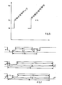
- the composite signal received by the circuit 29 comprises two synchronising signals, being a horizontal synchronising signal 46 and a vertical synchronising signal 47 respectively (see Figure 7).
- the signal 46 (see Figure 7) is at a frequency of about 26 KHz which is constant for the two formats and comprises a portion of duration T1 of around 27 ⁇ sec during which the signals in respect of the pixels of the line are generated, and a portion of a duration T2 of around 34 ⁇ sec which is active for scanning of the entire line.
- a pulse of a duration T3 of around 4.5 ⁇ sec is produced.
- the total time for scanning a line, as indicated at T4, is therefore about 38.5 ⁇ sec.
- the signal 47 depends on the display format preselected by the central unit 10.
- the signal 47 is of a frequency of around 60 Hz and comprises a portion of a duration T5 of around 15.5 msec in which the signals H are generated and a portion of a duration T6 of around 16.6 msec which is active for scanning of the entire frame.
- the total time for scanning the frame, as indicated at T8, is therefore around 16.7 msec.
- the frame scanning time T ⁇ 8 is now 14.7 msec.
- the selection circuit 30 (see Figure 2) is capable of sensing the duration of the signal P supplied by the circuit 27 for correspondingly controlling the vertical deflection circuit 28.
- the latter is normally operable to provide for vertical deflection at a frequency corresponding to the video format of 400 lines.
- the circuit 30 (see Figure 5) comprises an integrator formed by a resistor R20 and a capacitor C6, which integrates the pulse P supplied by the circuit 27 ( Figure 2).
- the integrator R20, C6 is operable to produce a voltage of 2V in the case of the 400 line format and a voltage of 8V in the case of the 350 line format.
- That voltage is applied to an input of an operational amplifier A1 whose other input is connected to a reference voltage divider R21, R22.
- the amplifier A1 outputs a voltage of +12V while in the case of the voltage of 2V, that output remains blocked.
- the circuit 30 further comprises a univibrator formed by another amplifier A2 and a circuit R23, C7.
- the period of that univibrator is about 25 msec, that is to say greater than the 400 line frame scanning time T8.
- An input of the amplifier A2 is connected by way of the capacitor C8 and a voltage dividier R24, R25 to the output of the amplifier A1.
- the other input of the amplifier A2 is triggered by a third amplifier A3 which receives the pulse P and the reference signal from the voltage divider R21, R22 whereby the univibrator A2, R23, C7 is continuously triggered.
- the output of the amplifier A2 is connected by means of a diode D7 and a resistor R26 to an input of the circuit 28 ( Figure 2).
- the output of the amplifier A1 is at +12V
- the output of the amplifier A2 supplies the circuit 28 with a command such as to vary the frequency of vertical deflection in such a way as to produce the 350 lines of the frame
- the visual frame size regulating circuit 31 essentially comprises an operational amplifier A4 (see Figure 5) which operates as an inverting gate.
- An input of the amplifier A4 is connected to the voltage divider R21, R22 while the other input is connected to the output of the amplifier A2.
- the output of the amplifier A4 is connected by way of a diode D8 to a second variable resistor RV2 which is connected to another input of the circuit 28 and is regulated at the time of setting up the apparatus for regulating the magnitude of vertical deflection and thus the size of the visual frame of the video in the 350 line format.
- circuits described may be integrated in one or more chips.
- the two circuits 30 and 31 may be formed by the integrated circuit LM 339 marketed by TEXAS INSTRUMENT.
Landscapes
- Engineering & Computer Science (AREA)
- Physics & Mathematics (AREA)
- Computer Hardware Design (AREA)
- General Physics & Mathematics (AREA)
- Theoretical Computer Science (AREA)
- Radar, Positioning & Navigation (AREA)
- Remote Sensing (AREA)
- Details Of Television Scanning (AREA)
- Video Image Reproduction Devices For Color Tv Systems (AREA)
- Controls And Circuits For Display Device (AREA)
Applications Claiming Priority (2)
| Application Number | Priority Date | Filing Date | Title |
|---|---|---|---|
| IT8767248A IT1207548B (it) | 1987-03-31 | 1987-03-31 | Dispositivo per la visualizzazione di dati di informatica mediante pixel su un tubo a raggi catodici |
| IT6724887 | 1987-03-31 |
Publications (2)
| Publication Number | Publication Date |
|---|---|
| EP0285250A2 true EP0285250A2 (fr) | 1988-10-05 |
| EP0285250A3 EP0285250A3 (fr) | 1990-05-23 |
Family
ID=11300828
Family Applications (1)
| Application Number | Title | Priority Date | Filing Date |
|---|---|---|---|
| EP88301575A Withdrawn EP0285250A3 (fr) | 1987-03-31 | 1988-02-24 | Dispositif de visualisation de données de traitement au moyen d'éléments d'image sur un tube à rayon cathodique |
Country Status (4)
| Country | Link |
|---|---|
| US (1) | US4875035A (fr) |
| EP (1) | EP0285250A3 (fr) |
| JP (1) | JPS63257786A (fr) |
| IT (1) | IT1207548B (fr) |
Families Citing this family (2)
| Publication number | Priority date | Publication date | Assignee | Title |
|---|---|---|---|---|
| US5079544A (en) * | 1989-02-27 | 1992-01-07 | Texas Instruments Incorporated | Standard independent digitized video system |
| CN105355161B (zh) * | 2015-12-05 | 2018-06-15 | 中国航空工业集团公司洛阳电光设备研究所 | 一种平视显示器防亮点烧蚀保护方法和保护装置 |
Family Cites Families (8)
| Publication number | Priority date | Publication date | Assignee | Title |
|---|---|---|---|---|
| BE745978A (fr) * | 1969-02-20 | 1970-07-16 | Thomson Csf | Systeme de visualisation |
| US3898644A (en) * | 1973-09-13 | 1975-08-05 | Qsi Systems Inc | TV display system |
| US4296476A (en) * | 1979-01-08 | 1981-10-20 | Atari, Inc. | Data processing system with programmable graphics generator |
| US4338597A (en) * | 1980-03-06 | 1982-07-06 | Honeywell Information Systems Inc. | Remote monitor interface |
| US4574279A (en) * | 1982-11-03 | 1986-03-04 | Compaq Computer Corporation | Video display system having multiple selectable screen formats |
| US4727362A (en) * | 1984-07-16 | 1988-02-23 | International Business Machines Corporation | Digital display system |
| GB8431038D0 (en) * | 1984-12-07 | 1985-01-16 | Ncr Co | Circuit means |
| JPS61198275A (ja) * | 1985-02-28 | 1986-09-02 | 株式会社東芝 | モノクロ階調表示装置 |
-
1987
- 1987-03-31 IT IT8767248A patent/IT1207548B/it active
-
1988
- 1988-02-24 EP EP88301575A patent/EP0285250A3/fr not_active Withdrawn
- 1988-02-29 US US07/162,252 patent/US4875035A/en not_active Expired - Fee Related
- 1988-03-28 JP JP63074271A patent/JPS63257786A/ja active Pending
Also Published As
| Publication number | Publication date |
|---|---|
| IT1207548B (it) | 1989-05-25 |
| US4875035A (en) | 1989-10-17 |
| EP0285250A3 (fr) | 1990-05-23 |
| IT8767248A0 (it) | 1987-03-31 |
| JPS63257786A (ja) | 1988-10-25 |
Similar Documents
| Publication | Publication Date | Title |
|---|---|---|
| DE69514143T2 (de) | Bildverarbeitungsvorrichtung und -verfahren | |
| US5914729A (en) | Visual frame buffer architecture | |
| US5654743A (en) | Picture display arrangement | |
| EP0170816A2 (fr) | Système d'affichage numérique comportant un T.R.C. à balayage à trame | |
| JP3201039B2 (ja) | 表示装置 | |
| JPS58207081A (ja) | カラ−印刷デ−タを修正する方法および該方法の実施に用いられる装置 | |
| US6816131B2 (en) | Single horizontal scan range CRT monitor | |
| US4233564A (en) | Apparatus for changing the scale of a logarithmic signal | |
| EP0366871B1 (fr) | Appareil pour le traitement d'un signal vidéo | |
| EP0387550A1 (fr) | Dispositif de contrôle d'affichage | |
| US6259439B1 (en) | Color lookup table blending | |
| US4875035A (en) | Arrangement for the display of processing data by means of pixels on a cathode ray tube | |
| US6606088B1 (en) | LCD panel signal processor | |
| US4783650A (en) | Data display arrangement | |
| EP0500100B1 (fr) | Système synthétiseur de signal vidéo pour synthétiser le signal propre au système et un signal externe | |
| US5334998A (en) | Method and apparatus for utilizing blanking on both zero setup and pedestal setup display monitors with a conventional computer system | |
| DE19600195C2 (de) | Bildsignalverarbeitungseinrichtung und Verfahren zur Verarbeitung digitaler Datensignale | |
| US4710771A (en) | Computer image display apparatus | |
| JP2001249655A (ja) | 表示装置 | |
| US4698681A (en) | Dual intensity video circuit | |
| JP3524115B2 (ja) | 輪郭補正装置 | |
| JP3353325B2 (ja) | 画面形状調整用管面表示装置 | |
| EP0615185A1 (fr) | Terminal d'ordinateur intégré | |
| JPS5977487A (ja) | パタ−ン表示駆動装置 | |
| JPH07162778A (ja) | 映像システムのosd回路 |
Legal Events
| Date | Code | Title | Description |
|---|---|---|---|
| PUAI | Public reference made under article 153(3) epc to a published international application that has entered the european phase |
Free format text: ORIGINAL CODE: 0009012 |
|
| AK | Designated contracting states |
Kind code of ref document: A2 Designated state(s): CH DE ES FR GB LI NL SE |
|
| PUAL | Search report despatched |
Free format text: ORIGINAL CODE: 0009013 |
|
| AK | Designated contracting states |
Kind code of ref document: A3 Designated state(s): CH DE ES FR GB LI NL SE |
|
| 17P | Request for examination filed |
Effective date: 19901112 |
|
| 17Q | First examination report despatched |
Effective date: 19920909 |
|
| STAA | Information on the status of an ep patent application or granted ep patent |
Free format text: STATUS: THE APPLICATION IS DEEMED TO BE WITHDRAWN |
|
| 18D | Application deemed to be withdrawn |
Effective date: 19930923 |