EP0285258A2 - Reaktivitätskontrolle in Kernreaktoren - Google Patents
Reaktivitätskontrolle in Kernreaktoren Download PDFInfo
- Publication number
- EP0285258A2 EP0285258A2 EP88301736A EP88301736A EP0285258A2 EP 0285258 A2 EP0285258 A2 EP 0285258A2 EP 88301736 A EP88301736 A EP 88301736A EP 88301736 A EP88301736 A EP 88301736A EP 0285258 A2 EP0285258 A2 EP 0285258A2
- Authority
- EP
- European Patent Office
- Prior art keywords
- sub
- assembly
- reactor
- housing
- coolant
- Prior art date
- Legal status (The legal status is an assumption and is not a legal conclusion. Google has not performed a legal analysis and makes no representation as to the accuracy of the status listed.)
- Withdrawn
Links
Images


Classifications
-
- G—PHYSICS
- G21—NUCLEAR PHYSICS; NUCLEAR ENGINEERING
- G21C—NUCLEAR REACTORS
- G21C9/00—Emergency protection arrangements structurally associated with the reactor, e.g. safety valves provided with pressure equalisation devices
- G21C9/02—Means for effecting very rapid reduction of the reactivity factor under fault conditions, e.g. reactor fuse; Control elements having arrangements activated in an emergency
-
- G—PHYSICS
- G21—NUCLEAR PHYSICS; NUCLEAR ENGINEERING
- G21C—NUCLEAR REACTORS
- G21C3/00—Reactor fuel elements and their assemblies; Selection of substances for use as reactor fuel elements
- G21C3/30—Assemblies of a number of fuel elements in the form of a rigid unit
- G21C3/32—Bundles of parallel pin-, rod-, or tube-shaped fuel elements
- G21C3/324—Coats or envelopes for the bundles
-
- G—PHYSICS
- G21—NUCLEAR PHYSICS; NUCLEAR ENGINEERING
- G21C—NUCLEAR REACTORS
- G21C7/00—Control of nuclear reaction
- G21C7/30—Control of nuclear reaction by displacement of the reactor fuel or fuel elements
-
- Y—GENERAL TAGGING OF NEW TECHNOLOGICAL DEVELOPMENTS; GENERAL TAGGING OF CROSS-SECTIONAL TECHNOLOGIES SPANNING OVER SEVERAL SECTIONS OF THE IPC; TECHNICAL SUBJECTS COVERED BY FORMER USPC CROSS-REFERENCE ART COLLECTIONS [XRACs] AND DIGESTS
- Y02—TECHNOLOGIES OR APPLICATIONS FOR MITIGATION OR ADAPTATION AGAINST CLIMATE CHANGE
- Y02E—REDUCTION OF GREENHOUSE GAS [GHG] EMISSIONS, RELATED TO ENERGY GENERATION, TRANSMISSION OR DISTRIBUTION
- Y02E30/00—Energy generation of nuclear origin
- Y02E30/30—Nuclear fission reactors
Definitions
- This invention relates to the control of reactivity in nuclear reactors.
- US Patent No 4131510 discloses an electromagnetically-operated core restraint structure which normally restrains radial dilation of the core but, in response to a temperature rise above the Curie point of the ferromagnetic materials employed, is disabled to permit radial dilation and thereby reduce reactivity.
- British Patent No 1176646 is concerned with a different approach in which the fuel sub-assemblies forming the core are mounted at their lower ends via ball joints seating in bearing cups fabricated from materials having differing coefficients of thermal expansion.
- the differing expansions lead to deflections of the sub-assemblies about the ball joints in directions corresponding to core dilation.
- US Patent No 3600276 discloses a reactivity control arrangement for a nuclear reactor core in which the fuel sub-assemblies contact one another through the agency of inclined contact faces acting in the manner of wedges, the fuel sub-assemblies being arranged in groups with differing mounting arrangements so that one group undergoes displacement relative to the other when the sub-assemblies undergo thermal expansion.
- British Patent Applications Nos 2048552A and 2064202A disclose grid designs for pressurised water reactor core fuel elements in which bimetallic components are incorporated in certain ones of the fuel element grids in order to control bowing of the fuel elements during reactor operation.
- An object of the present invention is to provide improved reactivity control means for a nuclear reactor core.
- a fuel sub-assembly for a nuclear reactor comprising an elongated tubular housing having, at or adjacent opposite ends thereof, coolant inlet means and coolant outlet means respectively, a coolant traversable fuel-bearing region enclosed within the housing between the inlet means and the outlet means, at least one elongate element located within, and extending generally longitudinally of, the housing so as to undergo longitudinal expansion as the temperature of the coolant increases, and radially extensible means responsive to longitudinal expansion of said element for projecting beyond the outer periphery of the housing so as to effect, in use, relative displacement between the sub-assembly and a neighbouring sub-assembly or sub-assemblies.
- a nuclear reactor comprising a plurality of elongated, generally vertically-orientated fuel sub-assemblies mounted in side-by-side relation and supported at their lower ends by a core support structure, each sub-assembly comprising an elongated tubular housing having coolant inlet means at or adjacent its lower end and coolant outlet means at or adjacent its upper end and enclosing, at a level intermediate the inlet and outlet means, a fuel-bearing region which the coolant traverses in flowing through the housing from the inlet means to the outlet means, at least some of the fuel sub-assemblies each being provided with at least one elongate element located within, and extending generally longitudinally of, the housing and radially extensible means for translating longitudinal thermal expansion of said elongate element into displacement of the associated sub-assembly relative to at least one neighbouring sub-assembly.
- the core assembly of a LMFBR comprises an array 10 of fuel sub-assemblies 11, each generally of the form shown in Figure 2, mounted on a diagrid 12 through which the coolant, normally liquid sodium, from the so-called cold pool is supplied.
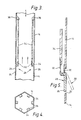
- each sub-assembly comprises a tubular housing or wrapper 14 which, over the major part of its length, is of hexagonal section and is fabricated from a ferritic steel.
- the wrapper 14 at its lower end terminates in a spike member 16 by means of which the sub-assembly plugs into the diagrid structure 12.
- the spike member 16 includes inlet apertures 18 through which coolant enters the wrapper before flowing upwardly (see arrows) through the latter and discharging into the hot sodium pool via the outlet end 20 of the sub-assembly.
- the coolant In passing upwardly from the inlet 18 to the outlet 20, the coolant traverses the fuel-bearing region 22, the fuel being in the form of pellets encapsulated in elongated sealed cans which are located in generally parallel spaced relation by wires or grids to allow coolant flow through the gaps.
- the fuel may be fissile and/or fertile.
- the sub-assemblies 11 are in effect mounted, via their spike members 16, in cantilevered fashion from the diagrid with the lower support plane for the core array located at the level Y-Y.
- the sub-assemblies 11 are arranged to make contact with each other at the higher plane X-X. Such contact may be though support or abutment pads 21 projecting from the faces of the wrapper in this region.
- a reactivity control mechanism is provided, preferably within each sub-assembly of the array, which serves to control reactivity by effecting radial dilation of the reactor in response to coolant temperature increase as a result of power increase or reduction in the coolant flow rate.
- Various embodiments of the mechanism are shown in Figures 3-14; in each instance, the mechanism is based on differential thermal expansion as will become apparent from the following description.
- each face of the wrapper 14 is formed with an aperture 24 which, normally, is substantially closed by one arm 26 of a respective cranked lever 28 which is connected to the wrapper by a mounting arm 30 having sufficient resilience to flex and allow the lever 28 to undergo pivotal movement as indicated in broken outline in Figure 5.
- a second lever arm 32 of the cranked lever 28 is coupled to the free end of a respective rod 34 which extends longitudinally of the wrapper 14 and is axially restrained at its opposite end by a fixed abutment 36.
- the rods 34 are composed of a material which has a larger coefficient of linear thermal expansion than the wrapper material.
- the rods 34 may be of austenitic steel while the wrapper may be of ferritic steel, the latter material having a linear thermal expansion coefficient of the order of 50% less than that of austenitic steel.
- the design may be such that the sub-assembly reactivity control mechanisms are effective to create sufficient dilation of the core to shut the core down in the event that the coolant temperature rises to a preselected value, eg of the order of 100°C above the sub-assembly outlet temperatures when the reactor is operating under normal conditions.
- control mechanism design may be such that a thermostat effect is achieved, ie core dilation occurs so as to maintain the sub-assembly outlet temperature constant.
- the invention has the potential for providing a reactor core which is intrinsically safe against factors such as rod withdrawal faults, loss of pumping power due to for example loss of station electrical supplies, and failure of heat transport systems due to failure of secondary circuits.
- Figures 6-8 is generally similar to that of Figures 3-5 and, where appropriate, the same reference numerals are used to identify components common to both embodiments; the same applies to the embodiments of Figures 9-11 and Figures 12-14.
- the levers 28 are operated by the free end of a cylinder 40 of for example austenitic steel connected to a wrapper 14 of for example ferritic steel.
- the embodiment of Figures 9-11 also employs an annular form of lever-operating mechanism.
- the operating mechanism effectively acts as a displacement amplifier in that a nest of serially connected cylinders 42, 44, 46 act between the wrapper 14 and the levers 28.
- the upper end of the outer cylinder 42 is connected at 48 to the wrapper and at its lower end to the lower end of the intermediate cylinder 44 which, in turn, is connected at its upper end to the upper end of the inner cylinder 46 whose lower end is linked to the arms 32 of the levers 28.
- the cylinders 42 and 46 are composed of a material, eg ferritic steel, having a larger linear thermal expansion coefficient than the intermediate cylinder 44 which may be of austenitic steel.
- the lever-operating mechanism comprises an axially expansible and contractible bellows 50 acting between the wrapper 14 and the arms 32 of the levers 28.
- the bellows 50 is fabricated from a bimetallic laminate, ie two layers 52, 54 having differing coefficients of thermal expansion.
- the reactivity control mechanisms are completely immersed in the coolant.
- the components constituting the mechanisms may be of thin sections, typically 1-3mm, and consequently have a short thermal time constant thereby enabling the mechanism to respond promptly to fault conditions.
Landscapes
- Physics & Mathematics (AREA)
- Engineering & Computer Science (AREA)
- Plasma & Fusion (AREA)
- General Engineering & Computer Science (AREA)
- High Energy & Nuclear Physics (AREA)
- Chemical & Material Sciences (AREA)
- Chemical Kinetics & Catalysis (AREA)
- Structure Of Emergency Protection For Nuclear Reactors (AREA)
- Monitoring And Testing Of Nuclear Reactors (AREA)
- Liquid Carbonaceous Fuels (AREA)
Applications Claiming Priority (2)
| Application Number | Priority Date | Filing Date | Title |
|---|---|---|---|
| GB878707614A GB8707614D0 (en) | 1987-03-31 | 1987-03-31 | Reactivity control in nuclear reactors |
| GB8707614 | 1987-03-31 |
Publications (2)
| Publication Number | Publication Date |
|---|---|
| EP0285258A2 true EP0285258A2 (de) | 1988-10-05 |
| EP0285258A3 EP0285258A3 (de) | 1989-11-08 |
Family
ID=10614949
Family Applications (1)
| Application Number | Title | Priority Date | Filing Date |
|---|---|---|---|
| EP88301736A Withdrawn EP0285258A3 (de) | 1987-03-31 | 1988-02-29 | Reaktivitätskontrolle in Kernreaktoren |
Country Status (4)
| Country | Link |
|---|---|
| US (1) | US4943409A (de) |
| EP (1) | EP0285258A3 (de) |
| JP (1) | JPS63256889A (de) |
| GB (1) | GB8707614D0 (de) |
Cited By (1)
| Publication number | Priority date | Publication date | Assignee | Title |
|---|---|---|---|---|
| EP2674948A4 (de) * | 2011-02-10 | 2017-11-22 | Tokyo Institute of Technology | Kernreaktor und stromerzeugungsanlage |
Families Citing this family (10)
| Publication number | Priority date | Publication date | Assignee | Title |
|---|---|---|---|---|
| IT1231553B (it) * | 1989-04-13 | 1991-12-17 | Enea | Meccanismo di sgancio automatico per barre di controllo in un reattore nucleare |
| US6370214B1 (en) * | 1999-07-08 | 2002-04-09 | Framtome Anp Inc. | Radiation induced growth indication apparatus for pressurized water reactor nuclear fuel assemblies |
| JP2013517479A (ja) * | 2010-01-13 | 2013-05-16 | アドバンスト・リアクター・コンセプツ・エルエルシー | シースで被覆された環状の金属核燃料 |
| JP6001457B2 (ja) * | 2010-02-22 | 2016-10-05 | アドバンスト・リアクター・コンセプツ・エルエルシー | 長い燃料交換間隔を有する小型の高速中性子スペクトル原子力発電所の高速中性子スペクトル原子炉システム、原子力を提供する方法、及び、炉心の締め付けのためのシステム |
| CA2820125C (en) * | 2010-11-15 | 2021-02-16 | Atomic Energy Of Canada Limited (Aecl) | Nuclear fuel containing recycled and depleted uranium, and nuclear fuel bundle and nuclear reactor comprising same |
| FR3012657A1 (fr) * | 2013-10-29 | 2015-05-01 | Commissariat Energie Atomique | Assemblage pour reacteur a neutrons rapides, refroidi par un metal liquide et comportant un plenum a vidange amelioree |
| CA3194118A1 (en) | 2014-04-14 | 2015-10-22 | Advanced Reactor Concepts LLC | Ceramic nuclear fuel dispersed in a metallic alloy matrix |
| ITUA20163714A1 (it) * | 2016-05-04 | 2017-11-04 | Luciano Cinotti | Reattore nucleare, con elementi di combustibile muniti di espansori |
| CA3045967C (en) * | 2016-12-22 | 2024-06-04 | Terrapower, Llc | Passive reactivity control in a nuclear fission reactor |
| FR3068820B1 (fr) * | 2017-07-06 | 2020-10-23 | Commissariat Energie Atomique | Assemblage pour reacteur nucleaire de type rnr-na, a liaison sans soudure reversible entre le boitier d'assemblage et un element d'assemblage insere dans le boitier |
Family Cites Families (16)
| Publication number | Priority date | Publication date | Assignee | Title |
|---|---|---|---|---|
| GB1151356A (en) * | 1965-08-26 | 1969-05-07 | Euratom | Improvements relating to Control Means for Fast Nuclear Reactors |
| GB1176646A (en) * | 1966-04-06 | 1970-01-07 | Atomic Energy Authority Uk | Improvements in or relating to Nuclear Reactors. |
| US3661708A (en) * | 1968-05-09 | 1972-05-09 | Atomic Power Dev Ass Inc | Fuel subassembly for nuclear reactor |
| US3600276A (en) * | 1968-10-07 | 1971-08-17 | John B Nims Jr | Fuel systems for nuclear reactors |
| US3549491A (en) * | 1968-11-21 | 1970-12-22 | Atomic Energy Commission | Nuclear reactor fuel element hold-down and tightening mechanism |
| GB1226264A (de) * | 1969-05-30 | 1971-03-24 | ||
| DE2010927C3 (de) * | 1970-03-07 | 1980-02-14 | Kernforschungszentrum Karlsruhe Gmbh, 7500 Karlsruhe | Brennelement fur einen Kernreaktor mit hohem und schnellem Neutronenfluß x |
| DE2162171C3 (de) * | 1971-12-15 | 1979-09-20 | Kernforschungszentrum Karlsruhe Gmbh, 7500 Karlsruhe | Verspannungssystem für Kernelemente eines Reaktorkernes |
| JPS549279B2 (de) * | 1972-07-12 | 1979-04-23 | ||
| GB1402936A (en) * | 1972-12-14 | 1975-08-13 | Atomic Energy Authority Uk | Nuclear reactor fuel element assemblies |
| US4038133A (en) * | 1973-04-19 | 1977-07-26 | Siemens Aktiengesellschaft | Nuclear reactor with suspended fuel assemblies having secondary emergency suspensions |
| US3964969A (en) * | 1974-06-20 | 1976-06-22 | The United States Of America As Represented By The United States Energy Research And Development Administration | Internal core tightener |
| US4104120A (en) * | 1977-01-21 | 1978-08-01 | Combustion Engineering, Inc. | Static fuel holddown system |
| US4227967A (en) * | 1977-06-03 | 1980-10-14 | Electric Power Research Institute, Inc. | Method and apparatus for reducing the power level in a nuclear reactor during temperature transient |
| US4295935A (en) * | 1979-03-29 | 1981-10-20 | Combustion Engineering, Inc. | Bimetallic spacer means for a nuclear fuel assembly |
| US4325786A (en) * | 1979-11-29 | 1982-04-20 | Combustion Engineering, Inc. | Spacer grid for reducing bowing in a nuclear fuel assembly |
-
1987
- 1987-03-31 GB GB878707614A patent/GB8707614D0/en active Pending
-
1988
- 1988-02-29 US US07/162,120 patent/US4943409A/en not_active Expired - Fee Related
- 1988-02-29 EP EP88301736A patent/EP0285258A3/de not_active Withdrawn
- 1988-03-09 JP JP63055916A patent/JPS63256889A/ja active Pending
Cited By (1)
| Publication number | Priority date | Publication date | Assignee | Title |
|---|---|---|---|---|
| EP2674948A4 (de) * | 2011-02-10 | 2017-11-22 | Tokyo Institute of Technology | Kernreaktor und stromerzeugungsanlage |
Also Published As
| Publication number | Publication date |
|---|---|
| JPS63256889A (ja) | 1988-10-24 |
| GB8707614D0 (en) | 1987-05-07 |
| EP0285258A3 (de) | 1989-11-08 |
| US4943409A (en) | 1990-07-24 |
Similar Documents
| Publication | Publication Date | Title |
|---|---|---|
| US4943409A (en) | Reactivity control in nuclear reactors | |
| US3379617A (en) | Means for supporting fuel elements in a nuclear reactor | |
| SE503854C2 (sv) | Kärnbränsleaggregat med stor kylmdelsförande tub | |
| KR830001096B1 (ko) | 핵 연료 집합체의 보우잉을 감소시키는 스페이서 그리드 | |
| JPH0222353B2 (de) | ||
| US3966550A (en) | Reactor fuel assemblies | |
| IL46627A (en) | Conditioning of nuclear reactor fuel | |
| US4227967A (en) | Method and apparatus for reducing the power level in a nuclear reactor during temperature transient | |
| TW571320B (en) | Fuel assembly for a pressurized-water reactor | |
| WO2014175939A1 (en) | Thermo-acoustic nuclear power distribution measurement assembly | |
| KR910005803B1 (ko) | 개량된 그리드 스트랩을 갖는 핵연료 스페이서 그리드 | |
| US4147591A (en) | Fuel assembly of fast breeder reactor | |
| US5787140A (en) | Handle assembly and channel for a nuclear reactor fuel bundle assembly | |
| US3600276A (en) | Fuel systems for nuclear reactors | |
| US20160099080A1 (en) | Nuclear fuel element corrugated plenum holddown device | |
| US4138320A (en) | Fluidic self-actuating control assembly | |
| US4152207A (en) | Magnetic nuclear core restraint and control | |
| WO1995024042A1 (en) | Critical power enhancement system for a pressurized fuel channel type nuclear reactor using chf enhancement appendages | |
| CN86107837A (zh) | 用于核反应堆的带有定心和防振定位装置的棒束导向装置 | |
| EP0976134A1 (de) | Kühlmittelmischgitter für kernrbrennstabbündel | |
| JP3494751B2 (ja) | 沸騰水型原子炉 | |
| JPS61237084A (ja) | 核燃料集合体 | |
| JPH0666973A (ja) | 金属燃料要素 | |
| Pickman | Interactions between fuel pins and assembly components | |
| JPH0556836B2 (de) |
Legal Events
| Date | Code | Title | Description |
|---|---|---|---|
| PUAI | Public reference made under article 153(3) epc to a published international application that has entered the european phase |
Free format text: ORIGINAL CODE: 0009012 |
|
| AK | Designated contracting states |
Kind code of ref document: A2 Designated state(s): BE DE FR GB IT |
|
| PUAL | Search report despatched |
Free format text: ORIGINAL CODE: 0009013 |
|
| AK | Designated contracting states |
Kind code of ref document: A3 Designated state(s): BE DE FR GB IT |
|
| RAP1 | Party data changed (applicant data changed or rights of an application transferred) |
Owner name: NNC LIMITED |
|
| 17P | Request for examination filed |
Effective date: 19900321 |
|
| RAP1 | Party data changed (applicant data changed or rights of an application transferred) |
Owner name: NNC LIMITED |
|
| STAA | Information on the status of an ep patent application or granted ep patent |
Free format text: STATUS: THE APPLICATION IS DEEMED TO BE WITHDRAWN |
|
| 18D | Application deemed to be withdrawn |
Effective date: 19910829 |