EP0285260A2 - Magnetostriktiver Drehmomentwandler - Google Patents
Magnetostriktiver Drehmomentwandler Download PDFInfo
- Publication number
- EP0285260A2 EP0285260A2 EP88301741A EP88301741A EP0285260A2 EP 0285260 A2 EP0285260 A2 EP 0285260A2 EP 88301741 A EP88301741 A EP 88301741A EP 88301741 A EP88301741 A EP 88301741A EP 0285260 A2 EP0285260 A2 EP 0285260A2
- Authority
- EP
- European Patent Office
- Prior art keywords
- shaft
- torque sensor
- sensor according
- tubular member
- torque
- Prior art date
- Legal status (The legal status is an assumption and is not a legal conclusion. Google has not performed a legal analysis and makes no representation as to the accuracy of the status listed.)
- Granted
Links
Images


Classifications
-
- G—PHYSICS
- G01—MEASURING; TESTING
- G01L—MEASURING FORCE, STRESS, TORQUE, WORK, MECHANICAL POWER, MECHANICAL EFFICIENCY, OR FLUID PRESSURE
- G01L5/00—Apparatus for, or methods of, measuring force, work, mechanical power, or torque, specially adapted for specific purposes
- G01L5/22—Apparatus for, or methods of, measuring force, work, mechanical power, or torque, specially adapted for specific purposes for measuring the force applied to control members, e.g. control members of vehicles, triggers
- G01L5/221—Apparatus for, or methods of, measuring force, work, mechanical power, or torque, specially adapted for specific purposes for measuring the force applied to control members, e.g. control members of vehicles, triggers to steering wheels, e.g. for power assisted steering
-
- G—PHYSICS
- G01—MEASURING; TESTING
- G01L—MEASURING FORCE, STRESS, TORQUE, WORK, MECHANICAL POWER, MECHANICAL EFFICIENCY, OR FLUID PRESSURE
- G01L3/00—Measuring torque, work, mechanical power, or mechanical efficiency, in general
- G01L3/02—Rotary-transmission dynamometers
- G01L3/04—Rotary-transmission dynamometers wherein the torque-transmitting element comprises a torsionally-flexible shaft
- G01L3/10—Rotary-transmission dynamometers wherein the torque-transmitting element comprises a torsionally-flexible shaft involving electric or magnetic means for indicating
- G01L3/101—Rotary-transmission dynamometers wherein the torque-transmitting element comprises a torsionally-flexible shaft involving electric or magnetic means for indicating involving magnetic or electromagnetic means
- G01L3/102—Rotary-transmission dynamometers wherein the torque-transmitting element comprises a torsionally-flexible shaft involving electric or magnetic means for indicating involving magnetic or electromagnetic means involving magnetostrictive means
-
- G—PHYSICS
- G01—MEASURING; TESTING
- G01L—MEASURING FORCE, STRESS, TORQUE, WORK, MECHANICAL POWER, MECHANICAL EFFICIENCY, OR FLUID PRESSURE
- G01L3/00—Measuring torque, work, mechanical power, or mechanical efficiency, in general
- G01L3/02—Rotary-transmission dynamometers
- G01L3/04—Rotary-transmission dynamometers wherein the torque-transmitting element comprises a torsionally-flexible shaft
- G01L3/10—Rotary-transmission dynamometers wherein the torque-transmitting element comprises a torsionally-flexible shaft involving electric or magnetic means for indicating
- G01L3/101—Rotary-transmission dynamometers wherein the torque-transmitting element comprises a torsionally-flexible shaft involving electric or magnetic means for indicating involving magnetic or electromagnetic means
- G01L3/105—Rotary-transmission dynamometers wherein the torque-transmitting element comprises a torsionally-flexible shaft involving electric or magnetic means for indicating involving magnetic or electromagnetic means involving inductive means
Definitions
- This invention relates to a torque sensor for detecting the torque of a rotating shaft, more particularly to a torque sensor suitable for measuring the torque of a drive shaft, steering shaft or other rotating shaft of an automobile and the like.
- the indirect type torque sensor which measures the torque of a shaft by sensing the amount of twist therein is unable to measure static torque. Because of this inadequacy, there have recently been introduced a number of direct type torque sensors operating on principles of which magnetostriction is an example. As an example of such a torque sensor there can be mentioned the one described in Japanese laid-open Patent Publication No. 57(1982)-211030, wherein a ribbon-like magnetostrictive strip is wound on a shaft whose torque is to be measured.
- the structure of the torque sensor disclosed by this publication requires that the magnetostrictive member be fixed directly on the shaft whose torque is to be measured so that the shaft itself becomes one component of the torque sensor. This is disadvantageous for several reasons. First, during manufacture of the torque sensor, it is generally necessary to attach the magnetostrictive member to a shaft of considerable length such as an automobile drive shaft, and this is difficult to do with high positional precision. Then, after the magnetostrictive member has been fixed on the shaft and up to the time that the shaft is installed in the vehicle, which is generally late in the assembly process, it is necessary to take great care in transporting and storing the shaft bearing the magnetostrictive member so as to protect the member from damage and adherence of dust or the like. The need to take these precautions greatly complicates the overall process of shaft installation.
- Another object of the invention is to provide a torque sensor wherein a magnetic element such as a magnetostrictive amorphous film is affixed on a member covered by a housing or an enclosure member so as to protect the film from damage at transportation, inventory and assembling while no special adjusting means is required for keeping the gap or distance between the film and detecting means to a predetermined value and which is enhanced in sensing accuracy.
- a magnetic element such as a magnetostrictive amorphous film
- the present invention provides a torque sensor comprising a shaft whose torque is to be measured.
- Said shaft is externally splined.
- it further comprises a tubular member mountable on the shaft, said tubular member being internally splined at its inner wall to fit to the external splines of the shaft when mounted thereon so as to receive transmission of the shaft rotation, a magnetic element provided at the outer wall of the tubular member responsive to the rotation thereof, an enclosure member housing said tubular member independently of its rotation and means for detecting change of magnetic characteristics of the element positioned at the inner wall of the enclosure member to measure the torque applied to the shaft.
- the tubular member 10 designates a tubular member.
- the tubular member 10 is substantially a true cylinder of circular cross-section and has a bore 14, best shown in Figure 8, of a diameter slightly larger than the diameter of a shaft 12 whose torque is to be measured.
- the bore 14 runs the full length of the tubular member 10.
- steps 16 are formed as annular protuberances such that a cylindrical portion 18 is constituted therebetween.
- the cylindrical portion 18 is of constant diameter throughout its full length and on the portion a magnetic element such as magnetic amorphous film 20 is fixed in an appropriate manner such as plating.
- the steps 16 can serve as a guide for placing the film on the portion in position.
- the steps 16 are followed by shoulder portions and an area left between the shoulder portions and the end becomes relatively so large in diameter as to form boss portions 22,22.
- the bore wall is grooved to form a number of key ways to form internal splines 24,24.
- the shaft 12 is provided with numerous keys to form external splines 26,26 at two portions, spaced apart from each other along the shaft length, corresponding to the position where the internal splines 24,24 are when the tubular member is mounted on the shaft such that the internal and external splines mesh together to permit the transmission of rotation.
- the portion 18 where the magnetic amorphous film 20 is affixed is left out of spline fitting such that the tubular member 10 is able to twist to produce stress in the film. It may be possible, however, to form either one of the splines at the shaft or boss portion throughout the length including the area provided that no mated pair to be meshed exists there. Further it should be noted that, when machining, tolerances should be held to the absolute minimum such that the shaft can be press fitted in the boss portion without causing any mechanical deformation. Thus, the shaft 12 will be securely engaged with the tubular member 10 without causing any slippage therebetween so that torque if applied to the shaft will be fully transmitted to the tubular member. A pair of rings 28,28 having open ends are provided on the shaft 12 near the ends of the tubular member 10 in order to prevent lateral movement of the member 10 along the shaft.
- a pair of bearings 34, 34 On the outer wall of the tubular member 10 are embeddedly fitted a pair of bearings 34, 34.
- the bearings 34,34 are provided at the outer surface of the boss portions 22,22 and outward of the bearings 34 is then provided a housing or an enclosure member 32 which serves as an outer covering for the unit.
- the reference numerals 36, 36 indicate oil seals and the reference numerals 38, 38 packings.
- the reference numerals 41, 41 and 40, 40 designate respectively rings embeddedly fitted in the tubular member and housing for preventing lateral movement of the housing through the bearings.
- the housing 32 has a cylindrical configuration wherein its central portion is constricted and is lessened in diameter to decrease its weight. And as shown in Figure 8, the housing wall rises locally at the constricted central portion to form a bulged portion 42. The bulged portion 42 is cut away at its top surface to provide an opening 44 which is closable by a cover 46.
- the cover 46 is square-shaped as clearly shown in Figure 1 and can be fastened to the opening by screws 52 screwed into threaded holes 50 provided in the housing through holes formed at ear-like portions 48 of the cover.
- a groove 54 is formed on the inner wall of the cover along its periphery.
- An O-ring 56 is provided in the groove for tight sealing (The ring is omitted in Figures 5 and 6).
- each of the cores extends a portion vertically to form legs 60a,62a,64a acting as a pole to the extent that the end surfaces 60b,62b,64b of the legs are in close proximity to the amorphous film, when assembled.
- the legs 62a,64a are longer than the leg 60a so as to keep a predetermined and uniform gap or distance "d", as shown in Figure 4.
- the end surface of the legs are rounded with the same radius of curvature as the outer surface of the tubular member on which the amorphous film is affixed in order to enhance sensing accuracy.
- the inner wall of the cover is made flat over the entire area including its periphery, so that it will be easy to set the height of the legs in order to keep the gap at a predetermined value, since the base is level for all the legs.
- the fact that the end surface of the legs is curved similarly to the film will be helpful to keep the gap constant.
- the periphery of the cover is also kept flat, so that the threaded holes 50 formed in the mated housing are also positioned at the coplanar level. Assembling is thus highly facilitated.
- a coil is wound on the central leg 60a to form an excitation coil 70 as viewed from Figure 5 and two detection coils 72, 72 are similarly wound on the remaining two legs 62a,64a in opposite winding directions.
- the two legs are disposed downwardly and symmetrically with respect to the central leg.
- the excitation coil 70 and detection coils 72, 72 are thus arranged such that flux paths generated therebetween are at ⁇ 45 degree angles with respect to the longitudinal axis of the tubular member 10 and the shaft 12; in other words, the flux paths coincide with the directions in which the compressive and tensile stress, if occurred when torque is applied to the shaft, becomes maximum.
- the magnetic amorphous film 20 must have been conferred, prior to being fixed on the tubular member 10, with uniaxial magnetic anisotropy oriented at the same angle degrees relative to the axis of the tubular member.
- the inner wall of the aforesaid cover 46 protrudes outwardly at an area surrounded by the coils so as to form a projection 80.
- the projection is opened at its end to provide a window 82 where grommet 84 rests.
- a harness 86 tying wires together and extending from the exterior passes through the grommet 84 and then branches out the wires respectively in the projection to be connected to the coils.
- a clamper 88 is provided at a position before the wires branch out.
- the clamper 88 has an omega-shape configuration in cross section comprising a base and a pipe portion extending from the base. The pipe portion is split axially in order to grasp the harness 86 firmly.
- the clamper 88 is fixed on the wall of the projection 80 with the base coupled with fixings extending from the projection wall.
- the harness 86 is thus gripped rigidly so that the wires will not be pulled out from the coils even when unexpected external tensile force happens on the harness.
- the grommet 84 is formed with two annular projections along the wall which are spaced apart from each other to prevent the grommet itself from being removed from the window 82.
- the window is filled up with plastics for sealing although it is not illustrated in the drawings.
- the shaft 12 is inserted in the bore 14 of the tubular member 10 and is placed in position to mesh the external and internal splines 24,26 together.
- the cover 46 is left un-attached to the housing at this stage.
- the rings 28 are put on the shaft near both ends of the member to block lateral movement of the member.
- the cover 46 is finally fastened to the housing and the sensor is now completed.
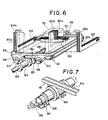
- the sensor, thus completed, is then fixed to the automobile.
- the sensor housing 32 is fastened, with a screw and a nut, to a bracket 93 mounted on the automobile body through a stay 92 extending from an annular wing 91 provided along the housing wall.
- the wing 91 is made of an elastic material such as a rubber and will absorb mechanical shock caused by the automobile, which might otherwise be transmitted to the sensor.
- the aforesaid coils are arranged such that lines connecting the magnetic poles thereof form a right isosceles triangle, with the excitation coil 70 positioned at the uppermost right angle and the two detection coils 72 located at the respective lower 45-degree angles, and further the flux paths between the coils coincide with the directions of the anisotropy, the detection coils are able to detect the change in permeability resulting from magnetostriction caused by the aforesaid application of torque, and produce outputs corresponding to the electromotive force induced therein.
- the torque sensor according to this invention is realized as an independent unit which does not use the shaft whose torque is to be measured as one of its constituent elements, it need only to be attached to the shaft at some appropriate stage of the vehicle assembly operation.
- the cylindrical member to which the magnetic amorphous film is attached is considerably shorter than the drive shaft or the like and is therefore much easier to handle. Further, the fact that the magnetic amorphous film is covered and protected by the housing member results in an additional increase in operational efficiency since less care is necessary for protecting it from damage and the adherence of dust and the like during transport, storage and mounting.
- the torque sensor is constructed as an independent unit might be expected to give rise to problems if its attachment to the shaft whose torque is to be detected should be such that slippage could occur between the two, since under such circumstances it would not be possible to carry out accurate detection, the torque sensor according to the present invention is entirely free from any such problem since it provides a highly reliable mounting based on the spline fitting.
- FIGS 11, 12 and 13 show a second embodiment of the torque sensor according to the invention. Briefly summing up how the sensor differs from that in the first embodiment before beginning detailed explanation of the structure, the shaft whose torque is to be measured is now cut into two halves and the sensor is provided therebetween.
- the sensor is a similar shape as was discussed in the first embodiment except that there is used a solid short shaft member, instead of the tubular member, functioning similarly as the tubular member in the first embodiment.
- the shaft member bears the magnetic amorphous film on the surface and is coupled with the two shaft halves through flange couplings.
- the sensor according to the second embodiment is particularly directed to make it more easy to mount the sensor on a long shaft such as a drive shaft of the vehicle.
- the reference numeral 100 indicates the aforesaid solid short shaft member.
- the shaft member 100 is circular in cross section and has a similar stiffness as the shaft whose torque is to be measured.
- the shaft member 100 is made large in diameter at the midway of the length to form a central portion 120, circular in cross section, at where the magnetic amorphous film 160 is affixed in position guided by steps 140,140.
- the shaft member 100 is provided with splines 180,180 in the vicinity of the respective ends 200,200. The ends have a threaded portions 220,220 respectively.
- Reference numeral 240 designates one half of the flange couplings associated with the other coupling half 340, positioned at the left of the shaft member in Figure 11.
- the coupling half 240 has a boss 260 and at the inner surface thereof internal splines 280 are formed to fit to the external splines 180 of the shaft member. Tolerance allowed therebetween is limited as little as possible similarly as those mentioned in the first embodiment.
- a recess 300 is formed in the boss 260 where the threaded end 200 of the shaft member sticks out. In the recess, the threaded end is fitted with a nut 320 and is fixed there.
- the other half 340 of the couplings receives likewise one half 360 of a shaft whose torque is to be measured.
- the two coupling halves are connected together by bolts 440 penetrating through holes 420, 441 formed at their flange portions 380,400 and nuts 460.
- flange couplings comprising a coupling half 480 and the other half 500 at the right side of the shaft member as shown in Figure 1.
- the coupling half 480 receives the opposite end of the shaft member 100 in its boss 520 meshing the external splines 180 with mating internal splines 540 formed at the boss hole.
- the shaft member end is then fixed in the recess 300 by a nut 560.
- the last coupling half 500 receives the end of the other half of the shaft whose torque is to be measured.
- the two coupling halves are fastened each other by bolts 660 which pass through holes 640,650 formed at flange portions 600,620 and fitted with nuts 680.
- the two shaft halves 360,580 of the shaft are thus coupled with shaft member 100 through the flange couplings.
- the applied torque will be transmitted to the shaft member 100 positioned therebetween.
- the size of the flange couplings and so on must be machined precisely such that the central axis of the shaft member aligns with those of the two shaft halves when coupled together.
- the housing 740 is similar in construction as that disclosed in the first embodiment.
- the housing has a wing 760 which is C-shaped in cross section and is made of a rubber material.
- the wing 760 has a stay 780 which will be connected to a bracket 840 mounted on the vehicle body through a bolt 800 and a nut 820, as shown in Figure 13.
- the reference numeral 860 indicates oil seals and the reference numeral 880 designates rings.
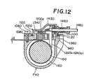
- the housing is raised to form a bulged portion 960 having an opening 980 which is closable by a cover 1000 by screws 1060 and washers 1080 sandwiching an O-ring 1120 therebetween for tight sealing.
- the cover is provided with, at its inner surface, three cores made of laminated silicon steel plates.
- the cores have legs 1200a, 1220a, 1240a respectively, and the end surface of the legs are made round so as to maintain the gap or distance "d" from the magnetic amorphous film 160 at a constant magnitude, as depicted in Figure 12.
- An exciting coil 1340 and two detection coils 1360 are wound around the core legs.
- the coils are connected to wires tied by a harness 1480 passing through a grommet 1460 resting in a window 1440 formed in a projection 1420. Since, however, these parts or portions are quite identical to those discussed in the first embodiment in structures and functions, detail explanation thereof will be omitted.
- the shaft member 100 is inserted in the housing 740.
- the coupling half 240 is connected to the one end of the shaft member 100 fitting the external splines 180 to the internal splines 280.
- the shaft end 200 is then fastened by the nut 320.
- the coupling half is then fastened, by the bolts 440 and nuts 460, to the coupling half 340 which has been coupled to the one half 360 of the shaft whose torque is to be measured.
- the shaft member 100 is connected to the third coupling half 480 which will in turn be fastened to the fourth coupling half 500 connected to the other shaft half 580.
- the cover 1000 is then attached to the housing 740.
- the housing 740 is finally connected to the bracket 840 through the stay 780 by the bolt 800 and the nut 820.
- the second and fourth coupling halves 340,500 may be fastened together. After completion, when a torsional force is applied to the shaft halves, the torque will be detected through the magnetic amorphous film and detection coils in the same manner as was explained in the first embodiment.
- the sensor according to the second embodiment is advantageous in that, in addition to the advantages mentioned with reference to the first embodiment, it will be more simply mounted on the shaft particularly when the shaft is of long length such as a vehicle drive shaft.
- a magnetic amorphous material is used, the invention is not limited to this and may use any material exhibiting similar magnetic characteristics.
Landscapes
- Physics & Mathematics (AREA)
- General Physics & Mathematics (AREA)
- Electromagnetism (AREA)
- Force Measurement Appropriate To Specific Purposes (AREA)
Applications Claiming Priority (8)
| Application Number | Priority Date | Filing Date | Title |
|---|---|---|---|
| JP4581587A JPS63210737A (ja) | 1987-02-27 | 1987-02-27 | トルクセンサ |
| JP4581487A JPS63210736A (ja) | 1987-02-27 | 1987-02-27 | トルクセンサ |
| JP4581787A JPS63210739A (ja) | 1987-02-27 | 1987-02-27 | トルクセンサ |
| JP45814/87 | 1987-02-27 | ||
| JP45817/87 | 1987-02-27 | ||
| JP45816/87 | 1987-02-27 | ||
| JP45815/87 | 1987-02-27 | ||
| JP4581687A JPS63210738A (ja) | 1987-02-27 | 1987-02-27 | トルクセンサ |
Publications (3)
| Publication Number | Publication Date |
|---|---|
| EP0285260A2 true EP0285260A2 (de) | 1988-10-05 |
| EP0285260A3 EP0285260A3 (en) | 1990-07-18 |
| EP0285260B1 EP0285260B1 (de) | 1993-02-10 |
Family
ID=27461785
Family Applications (1)
| Application Number | Title | Priority Date | Filing Date |
|---|---|---|---|
| EP88301741A Expired - Lifetime EP0285260B1 (de) | 1987-02-27 | 1988-02-29 | Magnetostriktiver Drehmomentwandler |
Country Status (3)
| Country | Link |
|---|---|
| US (2) | US4899597A (de) |
| EP (1) | EP0285260B1 (de) |
| DE (1) | DE3878278T2 (de) |
Cited By (9)
| Publication number | Priority date | Publication date | Assignee | Title |
|---|---|---|---|---|
| DE19515130A1 (de) * | 1995-04-25 | 1996-10-31 | Werner & Pfleiderer | Einrichtung zur Messung des Drehmomenteintrages bei Mehrwellenextrudern |
| WO1998025116A1 (en) * | 1996-12-04 | 1998-06-11 | Koninklijke Philips Electronics N.V. | Magnetoelastic torque sensor with shielding flux guide |
| EP0805091A3 (de) * | 1996-04-30 | 2000-04-26 | Eaton Corporation | Erfassen des Drehmoments in der Lenkwelle einer schwenkbaren Lenksäule |
| EP0786387A3 (de) * | 1996-01-26 | 2000-07-26 | Ssi Technologies, Inc. | Verfahren und Vorrichtung zur Bremspedal-Kraftmessung in einem Fahrzeug |
| EP1298051A3 (de) * | 2001-09-28 | 2005-12-14 | Kabushiki Kaisha Moric | Einheit mit elektrischem Hilfsantrieb |
| US9329093B2 (en) | 2011-08-10 | 2016-05-03 | Isis Innovation Limited | Determining torque in a shaft |
| EP3051265A1 (de) * | 2015-01-29 | 2016-08-03 | Torque and More (TAM) GmbH | Kraftmessvorrichtung |
| KR20160098723A (ko) * | 2015-02-11 | 2016-08-19 | 현대자동차주식회사 | 충격흡수가능한 스티어링 칼럼구조 |
| EP1808681B1 (de) * | 2006-01-12 | 2019-10-23 | JTEKT Corporation | Magnetische Drehmomentdetektionseinrichtung |
Families Citing this family (15)
| Publication number | Priority date | Publication date | Assignee | Title |
|---|---|---|---|---|
| US5255567A (en) * | 1990-06-30 | 1993-10-26 | Nippon Densan Corporation | Torque transducer |
| EP0502721B1 (de) * | 1991-03-04 | 1995-12-27 | Matsushita Electric Industrial Co., Ltd. | Berührungslos arbeitender Drehmomentmessfühler |
| DE4333199C2 (de) * | 1993-09-29 | 1995-08-31 | Daimler Benz Ag | Sensor zur berührungslosen Drehmomentmessung an einer Welle sowie Meßschicht für einen solchen Sensor |
| US5526704A (en) * | 1994-11-01 | 1996-06-18 | Unisia Jecs Corporation | Structure of magnetostrictive torque sensor applicable to sensor for detecting torque applied to rotatable shaft |
| JP3099680B2 (ja) * | 1995-02-13 | 2000-10-16 | 株式会社豊田自動織機製作所 | トルクセンサ及び歪み検出素子 |
| KR100500560B1 (ko) | 1997-03-28 | 2005-07-12 | 만네스만 파우데오 아게 | 자기탄성 트랜스듀서 제조 방법 |
| DE19907270A1 (de) * | 1999-02-20 | 2000-08-24 | Zahnradfabrik Friedrichshafen | Vorrichtung zur Messung des Drehmomentes einer Welle |
| DE10020643C2 (de) * | 2000-04-27 | 2002-02-28 | Daimler Chrysler Ag | Anordnung zum drehmomentfreien Schalten eines Getriebes |
| KR200470045Y1 (ko) * | 2008-12-16 | 2013-11-25 | 엘지이노텍 주식회사 | 일렉트릭 파워 스티어링 시스템 |
| US7886863B2 (en) * | 2009-02-12 | 2011-02-15 | American Axle & Manufacturing, Inc. | Driveshaft assembly with torque sensor |
| US9383273B2 (en) | 2011-05-24 | 2016-07-05 | Ford Global Technologies, Llc | Magnetic torque sensor packaging for automatic transmissions |
| US8844379B2 (en) | 2011-05-24 | 2014-09-30 | Ford Global Technologies, Llc | Transmissions with electronics interface assembly for torque sensor |
| US8827060B2 (en) | 2012-09-13 | 2014-09-09 | Ford Global Technologies, Llc | Transmission and method of controlling clutch during ratio change |
| US9285282B2 (en) | 2013-02-20 | 2016-03-15 | Ford Global Technologies, Llc | Magnetic sensor packaging for transmissions |
| DE102021115097B4 (de) | 2021-06-11 | 2025-01-16 | Schaeffler Technologies AG & Co. KG | Drehmomentübertragungsvorrichtung und Verfahren zum Schleppstart eines Verbrennungsmotors |
Family Cites Families (10)
| Publication number | Priority date | Publication date | Assignee | Title |
|---|---|---|---|---|
| CA655868A (en) * | 1963-01-15 | Dubsky Borivoj | Electromagnetic torsiometer | |
| US3111028A (en) * | 1960-08-22 | 1963-11-19 | Lebow Associates Inc | Torque meter |
| JPS46527Y1 (de) * | 1967-06-10 | 1971-01-09 | ||
| SU800727A1 (ru) * | 1976-12-14 | 1981-01-30 | Новосибирский Институт Инженеровводного Транспорта | Устройство дл измерени крут щегоМОМЕНТА HA ВРАщАющиХС ВАлАХ |
| JPS6088335A (ja) * | 1983-10-19 | 1985-05-18 | Nissan Motor Co Ltd | トルク検出装置 |
| DE3344385A1 (de) * | 1983-12-08 | 1985-06-20 | Robert Bosch Gmbh, 7000 Stuttgart | Beruehrungsfreie messvorrichtung fuer drehmoment und/oder drehwinkel |
| DE3407917A1 (de) * | 1984-03-03 | 1985-09-05 | Vacuumschmelze Gmbh, 6450 Hanau | Verfahren zum messen einer mechanischen spannung an einer welle |
| JPS60200138A (ja) * | 1984-03-24 | 1985-10-09 | Nippon Soken Inc | トルク検出装置 |
| US4566338A (en) * | 1984-07-20 | 1986-01-28 | Trw Inc. | Noncontact torque sensor |
| US4817444A (en) * | 1986-03-03 | 1989-04-04 | Honda Giken Kogyo Kabushiki Kaisha | Torque sensor |
-
1988
- 1988-02-26 US US07/160,682 patent/US4899597A/en not_active Expired - Fee Related
- 1988-02-29 DE DE8888301741T patent/DE3878278T2/de not_active Expired - Fee Related
- 1988-02-29 EP EP88301741A patent/EP0285260B1/de not_active Expired - Lifetime
-
1989
- 1989-10-23 US US07/426,321 patent/US4962672A/en not_active Expired - Fee Related
Cited By (10)
| Publication number | Priority date | Publication date | Assignee | Title |
|---|---|---|---|---|
| DE19515130A1 (de) * | 1995-04-25 | 1996-10-31 | Werner & Pfleiderer | Einrichtung zur Messung des Drehmomenteintrages bei Mehrwellenextrudern |
| EP0786387A3 (de) * | 1996-01-26 | 2000-07-26 | Ssi Technologies, Inc. | Verfahren und Vorrichtung zur Bremspedal-Kraftmessung in einem Fahrzeug |
| EP0805091A3 (de) * | 1996-04-30 | 2000-04-26 | Eaton Corporation | Erfassen des Drehmoments in der Lenkwelle einer schwenkbaren Lenksäule |
| WO1998025116A1 (en) * | 1996-12-04 | 1998-06-11 | Koninklijke Philips Electronics N.V. | Magnetoelastic torque sensor with shielding flux guide |
| EP1298051A3 (de) * | 2001-09-28 | 2005-12-14 | Kabushiki Kaisha Moric | Einheit mit elektrischem Hilfsantrieb |
| EP1808681B1 (de) * | 2006-01-12 | 2019-10-23 | JTEKT Corporation | Magnetische Drehmomentdetektionseinrichtung |
| US9329093B2 (en) | 2011-08-10 | 2016-05-03 | Isis Innovation Limited | Determining torque in a shaft |
| EP3051265A1 (de) * | 2015-01-29 | 2016-08-03 | Torque and More (TAM) GmbH | Kraftmessvorrichtung |
| WO2016119931A1 (en) * | 2015-01-29 | 2016-08-04 | Torque And More (Tam) Gmbh | Force measurement device |
| KR20160098723A (ko) * | 2015-02-11 | 2016-08-19 | 현대자동차주식회사 | 충격흡수가능한 스티어링 칼럼구조 |
Also Published As
| Publication number | Publication date |
|---|---|
| DE3878278D1 (de) | 1993-03-25 |
| EP0285260B1 (de) | 1993-02-10 |
| US4962672A (en) | 1990-10-16 |
| DE3878278T2 (de) | 1993-05-27 |
| EP0285260A3 (en) | 1990-07-18 |
| US4899597A (en) | 1990-02-13 |
Similar Documents
| Publication | Publication Date | Title |
|---|---|---|
| EP0285260B1 (de) | Magnetostriktiver Drehmomentwandler | |
| EP0285259B1 (de) | Magnetostriktiver Drehmomentwandler | |
| JP3316257B2 (ja) | ねじりモーメント測定装置 | |
| US4817444A (en) | Torque sensor | |
| US5889215A (en) | Magnetoelastic torque sensor with shielding flux guide | |
| US4697460A (en) | Device for measuring torque of a rotary mechanism | |
| US5831180A (en) | Torque sensing and strain detecting device | |
| US6978686B2 (en) | Torque sensor | |
| EP0651239A2 (de) | Magnetostriktiver Drehmomentsensor, magnetostriktive Drehmomentmessvorrichtung und Vorrichtung zur Überwachung des Zustandes eines Schneidwerkzeuges | |
| US5515736A (en) | Arrangement for compensating thermal characteristics of sensor | |
| JP2002296128A (ja) | 車両用トルクセンサ | |
| US20050160834A1 (en) | Assembly for measuring movement of and a torque applied to a shaft | |
| JP2564055B2 (ja) | 磁歪式トルクセンサの過負荷防止装置 | |
| JPS63210739A (ja) | トルクセンサ | |
| JPH0545240A (ja) | 磁歪式トルクセンサの過負荷防止装置 | |
| US5062307A (en) | Strain detector | |
| JPS63210737A (ja) | トルクセンサ | |
| JPS63210736A (ja) | トルクセンサ | |
| JPS63210738A (ja) | トルクセンサ | |
| JPS62203027A (ja) | トルクセンサ | |
| JPS6141936A (ja) | トルクセンサ | |
| US20040219984A1 (en) | Shunted collarless torsion shaft for electronic power-assisted steering systems | |
| JPS62203030A (ja) | トルクセンサ | |
| JPH0723713Y2 (ja) | トルクセンサ | |
| JPH0615994B2 (ja) | トルクセンサ |
Legal Events
| Date | Code | Title | Description |
|---|---|---|---|
| PUAI | Public reference made under article 153(3) epc to a published international application that has entered the european phase |
Free format text: ORIGINAL CODE: 0009012 |
|
| 17P | Request for examination filed |
Effective date: 19880315 |
|
| AK | Designated contracting states |
Kind code of ref document: A2 Designated state(s): DE GB |
|
| PUAL | Search report despatched |
Free format text: ORIGINAL CODE: 0009013 |
|
| AK | Designated contracting states |
Kind code of ref document: A3 Designated state(s): DE GB |
|
| 17Q | First examination report despatched |
Effective date: 19911129 |
|
| GRAA | (expected) grant |
Free format text: ORIGINAL CODE: 0009210 |
|
| AK | Designated contracting states |
Kind code of ref document: B1 Designated state(s): DE GB |
|
| REF | Corresponds to: |
Ref document number: 3878278 Country of ref document: DE Date of ref document: 19930325 |
|
| PLBE | No opposition filed within time limit |
Free format text: ORIGINAL CODE: 0009261 |
|
| STAA | Information on the status of an ep patent application or granted ep patent |
Free format text: STATUS: NO OPPOSITION FILED WITHIN TIME LIMIT |
|
| 26N | No opposition filed | ||
| PGFP | Annual fee paid to national office [announced via postgrant information from national office to epo] |
Ref country code: DE Payment date: 19940222 Year of fee payment: 7 |
|
| PGFP | Annual fee paid to national office [announced via postgrant information from national office to epo] |
Ref country code: GB Payment date: 19940225 Year of fee payment: 7 |
|
| PG25 | Lapsed in a contracting state [announced via postgrant information from national office to epo] |
Ref country code: GB Effective date: 19950228 |
|
| GBPC | Gb: european patent ceased through non-payment of renewal fee |
Effective date: 19950228 |
|
| PG25 | Lapsed in a contracting state [announced via postgrant information from national office to epo] |
Ref country code: DE Effective date: 19951101 |