EP0285290A2 - Hydraulische Hebevorrichtung für Tragbahren - Google Patents
Hydraulische Hebevorrichtung für Tragbahren Download PDFInfo
- Publication number
- EP0285290A2 EP0285290A2 EP88302346A EP88302346A EP0285290A2 EP 0285290 A2 EP0285290 A2 EP 0285290A2 EP 88302346 A EP88302346 A EP 88302346A EP 88302346 A EP88302346 A EP 88302346A EP 0285290 A2 EP0285290 A2 EP 0285290A2
- Authority
- EP
- European Patent Office
- Prior art keywords
- hydraulic
- cylinders
- stretcher
- piston
- pair
- Prior art date
- Legal status (The legal status is an assumption and is not a legal conclusion. Google has not performed a legal analysis and makes no representation as to the accuracy of the status listed.)
- Granted
Links
- 230000000712 assembly Effects 0.000 claims abstract description 7
- 238000000429 assembly Methods 0.000 claims abstract description 7
- 230000008093 supporting effect Effects 0.000 claims abstract description 4
- OKTJSMMVPCPJKN-UHFFFAOYSA-N Carbon Chemical compound [C] OKTJSMMVPCPJKN-UHFFFAOYSA-N 0.000 claims description 28
- 239000012530 fluid Substances 0.000 claims description 25
- 239000000463 material Substances 0.000 claims description 21
- 210000000707 wrist Anatomy 0.000 claims description 19
- 229910052799 carbon Inorganic materials 0.000 claims description 14
- 239000011152 fibreglass Substances 0.000 claims description 14
- 229910002804 graphite Inorganic materials 0.000 claims description 14
- 239000010439 graphite Substances 0.000 claims description 14
- 230000000452 restraining effect Effects 0.000 claims description 13
- 239000000088 plastic resin Substances 0.000 claims description 11
- 230000000087 stabilizing effect Effects 0.000 claims description 8
- 238000001990 intravenous administration Methods 0.000 claims description 7
- 239000004705 High-molecular-weight polyethylene Substances 0.000 claims description 6
- 238000003475 lamination Methods 0.000 claims description 6
- 239000011159 matrix material Substances 0.000 claims description 6
- 239000011347 resin Substances 0.000 claims description 6
- 229920005989 resin Polymers 0.000 claims description 6
- 239000004033 plastic Substances 0.000 claims description 5
- 229920003023 plastic Polymers 0.000 claims description 5
- 240000007182 Ochroma pyramidale Species 0.000 claims description 4
- 238000005086 pumping Methods 0.000 claims description 3
- 239000010410 layer Substances 0.000 claims 4
- 239000012792 core layer Substances 0.000 claims 1
- 230000005855 radiation Effects 0.000 claims 1
- 239000000835 fiber Substances 0.000 description 6
- 239000006260 foam Substances 0.000 description 6
- 239000003381 stabilizer Substances 0.000 description 5
- 239000004698 Polyethylene Substances 0.000 description 3
- 238000010276 construction Methods 0.000 description 3
- 208000014674 injury Diseases 0.000 description 3
- 238000004519 manufacturing process Methods 0.000 description 3
- 238000000034 method Methods 0.000 description 3
- -1 polyethylene Polymers 0.000 description 3
- 229920000573 polyethylene Polymers 0.000 description 3
- 230000003213 activating effect Effects 0.000 description 2
- XAGFODPZIPBFFR-UHFFFAOYSA-N aluminium Chemical compound [Al] XAGFODPZIPBFFR-UHFFFAOYSA-N 0.000 description 2
- 229910052782 aluminium Inorganic materials 0.000 description 2
- 230000008901 benefit Effects 0.000 description 2
- 230000008859 change Effects 0.000 description 2
- 230000006378 damage Effects 0.000 description 2
- 238000010586 diagram Methods 0.000 description 2
- 230000001965 increasing effect Effects 0.000 description 2
- 230000007246 mechanism Effects 0.000 description 2
- 229920000642 polymer Polymers 0.000 description 2
- 238000003860 storage Methods 0.000 description 2
- 230000008733 trauma Effects 0.000 description 2
- 208000010496 Heart Arrest Diseases 0.000 description 1
- FYYHWMGAXLPEAU-UHFFFAOYSA-N Magnesium Chemical compound [Mg] FYYHWMGAXLPEAU-UHFFFAOYSA-N 0.000 description 1
- 229910000831 Steel Inorganic materials 0.000 description 1
- 208000003443 Unconsciousness Diseases 0.000 description 1
- 208000027418 Wounds and injury Diseases 0.000 description 1
- 230000009471 action Effects 0.000 description 1
- 230000001464 adherent effect Effects 0.000 description 1
- 230000000903 blocking effect Effects 0.000 description 1
- 239000008280 blood Substances 0.000 description 1
- 210000004369 blood Anatomy 0.000 description 1
- 239000011248 coating agent Substances 0.000 description 1
- 238000000576 coating method Methods 0.000 description 1
- 230000007797 corrosion Effects 0.000 description 1
- 238000005260 corrosion Methods 0.000 description 1
- 239000002537 cosmetic Substances 0.000 description 1
- 238000003745 diagnosis Methods 0.000 description 1
- 230000003670 easy-to-clean Effects 0.000 description 1
- 230000000694 effects Effects 0.000 description 1
- 230000005611 electricity Effects 0.000 description 1
- 239000004744 fabric Substances 0.000 description 1
- 238000001891 gel spinning Methods 0.000 description 1
- 230000001976 improved effect Effects 0.000 description 1
- 230000001939 inductive effect Effects 0.000 description 1
- JEIPFZHSYJVQDO-UHFFFAOYSA-N iron(III) oxide Inorganic materials O=[Fe]O[Fe]=O JEIPFZHSYJVQDO-UHFFFAOYSA-N 0.000 description 1
- 229910052749 magnesium Inorganic materials 0.000 description 1
- 239000011777 magnesium Substances 0.000 description 1
- 230000035699 permeability Effects 0.000 description 1
- 229920001225 polyester resin Polymers 0.000 description 1
- 239000004645 polyester resin Substances 0.000 description 1
- 230000008569 process Effects 0.000 description 1
- 230000002285 radioactive effect Effects 0.000 description 1
- 230000000630 rising effect Effects 0.000 description 1
- 238000001228 spectrum Methods 0.000 description 1
- 239000010959 steel Substances 0.000 description 1
Images




Classifications
-
- A—HUMAN NECESSITIES
- A61—MEDICAL OR VETERINARY SCIENCE; HYGIENE
- A61G—TRANSPORT, PERSONAL CONVEYANCES, OR ACCOMMODATION SPECIALLY ADAPTED FOR PATIENTS OR DISABLED PERSONS; OPERATING TABLES OR CHAIRS; CHAIRS FOR DENTISTRY; FUNERAL DEVICES
- A61G7/00—Beds specially adapted for nursing; Devices for lifting patients or disabled persons
- A61G7/05—Parts, details or accessories of beds
- A61G7/0507—Side-rails
-
- A—HUMAN NECESSITIES
- A61—MEDICAL OR VETERINARY SCIENCE; HYGIENE
- A61B—DIAGNOSIS; SURGERY; IDENTIFICATION
- A61B6/00—Apparatus or devices for radiation diagnosis; Apparatus or devices for radiation diagnosis combined with radiation therapy equipment
- A61B6/04—Positioning of patients; Tiltable beds or the like
- A61B6/0407—Supports, e.g. tables or beds, for the body or parts of the body
- A61B6/0442—Supports, e.g. tables or beds, for the body or parts of the body made of non-metallic materials
-
- A—HUMAN NECESSITIES
- A61—MEDICAL OR VETERINARY SCIENCE; HYGIENE
- A61G—TRANSPORT, PERSONAL CONVEYANCES, OR ACCOMMODATION SPECIALLY ADAPTED FOR PATIENTS OR DISABLED PERSONS; OPERATING TABLES OR CHAIRS; CHAIRS FOR DENTISTRY; FUNERAL DEVICES
- A61G1/00—Stretchers
- A61G1/02—Stretchers with wheels
- A61G1/0206—Stretchers with wheels characterised by the number of supporting wheels if stretcher is extended
- A61G1/0212—2 pairs having wheels within a pair on the same position in longitudinal direction, e.g. on the same axis
-
- A—HUMAN NECESSITIES
- A61—MEDICAL OR VETERINARY SCIENCE; HYGIENE
- A61G—TRANSPORT, PERSONAL CONVEYANCES, OR ACCOMMODATION SPECIALLY ADAPTED FOR PATIENTS OR DISABLED PERSONS; OPERATING TABLES OR CHAIRS; CHAIRS FOR DENTISTRY; FUNERAL DEVICES
- A61G1/00—Stretchers
- A61G1/02—Stretchers with wheels
- A61G1/0237—Stretchers with wheels having at least one swivelling wheel, e.g. castors
-
- A—HUMAN NECESSITIES
- A61—MEDICAL OR VETERINARY SCIENCE; HYGIENE
- A61G—TRANSPORT, PERSONAL CONVEYANCES, OR ACCOMMODATION SPECIALLY ADAPTED FOR PATIENTS OR DISABLED PERSONS; OPERATING TABLES OR CHAIRS; CHAIRS FOR DENTISTRY; FUNERAL DEVICES
- A61G1/00—Stretchers
- A61G1/02—Stretchers with wheels
- A61G1/0275—Stretchers with wheels having driven wheels, e.g. motorised
-
- A—HUMAN NECESSITIES
- A61—MEDICAL OR VETERINARY SCIENCE; HYGIENE
- A61G—TRANSPORT, PERSONAL CONVEYANCES, OR ACCOMMODATION SPECIALLY ADAPTED FOR PATIENTS OR DISABLED PERSONS; OPERATING TABLES OR CHAIRS; CHAIRS FOR DENTISTRY; FUNERAL DEVICES
- A61G7/00—Beds specially adapted for nursing; Devices for lifting patients or disabled persons
- A61G7/002—Beds specially adapted for nursing; Devices for lifting patients or disabled persons having adjustable mattress frame
- A61G7/005—Beds specially adapted for nursing; Devices for lifting patients or disabled persons having adjustable mattress frame tiltable around transverse horizontal axis, e.g. for Trendelenburg position
-
- A—HUMAN NECESSITIES
- A61—MEDICAL OR VETERINARY SCIENCE; HYGIENE
- A61G—TRANSPORT, PERSONAL CONVEYANCES, OR ACCOMMODATION SPECIALLY ADAPTED FOR PATIENTS OR DISABLED PERSONS; OPERATING TABLES OR CHAIRS; CHAIRS FOR DENTISTRY; FUNERAL DEVICES
- A61G7/00—Beds specially adapted for nursing; Devices for lifting patients or disabled persons
- A61G7/002—Beds specially adapted for nursing; Devices for lifting patients or disabled persons having adjustable mattress frame
- A61G7/012—Beds specially adapted for nursing; Devices for lifting patients or disabled persons having adjustable mattress frame raising or lowering of the whole mattress frame
-
- A—HUMAN NECESSITIES
- A61—MEDICAL OR VETERINARY SCIENCE; HYGIENE
- A61G—TRANSPORT, PERSONAL CONVEYANCES, OR ACCOMMODATION SPECIALLY ADAPTED FOR PATIENTS OR DISABLED PERSONS; OPERATING TABLES OR CHAIRS; CHAIRS FOR DENTISTRY; FUNERAL DEVICES
- A61G7/00—Beds specially adapted for nursing; Devices for lifting patients or disabled persons
- A61G7/05—Parts, details or accessories of beds
- A61G7/0507—Side-rails
- A61G7/0508—Side-rails characterised by a particular connection mechanism
- A61G7/051—Side-rails characterised by a particular connection mechanism pivoting sideward
-
- A—HUMAN NECESSITIES
- A61—MEDICAL OR VETERINARY SCIENCE; HYGIENE
- A61G—TRANSPORT, PERSONAL CONVEYANCES, OR ACCOMMODATION SPECIALLY ADAPTED FOR PATIENTS OR DISABLED PERSONS; OPERATING TABLES OR CHAIRS; CHAIRS FOR DENTISTRY; FUNERAL DEVICES
- A61G7/00—Beds specially adapted for nursing; Devices for lifting patients or disabled persons
- A61G7/05—Parts, details or accessories of beds
- A61G7/0507—Side-rails
- A61G7/0512—Side-rails characterised by customised length
- A61G7/0515—Side-rails characterised by customised length covering the full bed length, e.g. from head board to foot board
-
- A—HUMAN NECESSITIES
- A61—MEDICAL OR VETERINARY SCIENCE; HYGIENE
- A61G—TRANSPORT, PERSONAL CONVEYANCES, OR ACCOMMODATION SPECIALLY ADAPTED FOR PATIENTS OR DISABLED PERSONS; OPERATING TABLES OR CHAIRS; CHAIRS FOR DENTISTRY; FUNERAL DEVICES
- A61G2210/00—Devices for specific treatment or diagnosis
- A61G2210/50—Devices for specific treatment or diagnosis for radiography
Definitions
- the invention relates to a trauma stretcher or cot for disabled, injured, or sick individuals. More particularly, this invention relates to stretchers for disabled individuals which can be desirably adjusted to facilitate their handling and treatment. Specifically this invention relates to a hydraulic stretcher device which can be positioned by means of hydraulic cylinders, and which also includes improved means for securing certain of the stretcher's adjustable features in desired positions, as well as a patient-supporting top suitable for X-ray examinations.
- stretchers employed for this purpose be capable of being raised or lowered, horizontally and otherwise, for ease of access by medical personnel, or for other reasons.
- the patient is physically unable to move, either because of unconsciousness or infirmity; consequently, the stretcher must be extremely stable to avoid the possibility of tipping or other misadventure during patient transportation or treatment.
- the stretcher is often subjected to unbalanced loads during use, increasing the risk of lateral tilting, therefore, adding to the importance of structural stability.
- Trendelenberg position is employed, for example, in the case of cardiac arrest, where the head of the patient is lowered to allow concentration of blood in the patient's head.
- certain features of stretcher devices such as restraining, or safety rails, intravenous support poles, etc., be securable in several positions.
- restraining, or safety rails, intravenous support poles, etc. be securable in several positions.
- they must be capable of being easily and reliably secured in the particular position selected.
- stretchers have been devised, both of the mechanical variety, as well as some hydraulically operated devices.
- stretchers of the mechanical type are not as convenient as hydraulic stretchers, since they require hand manipulation of the apparatus associated therewith to raise, lower, and otherwise position the stretcher devices.
- hydraulic stretchers heretofore proposed have generally been unstably supported by the hydraulic cylinders employed.
- their hydraulic controls have not been conveniently located, and oftentimes they have been of a type difficult to operate.
- a hydraulic stretcher when being raised, it occasionally encounters an obstructing obstacle.
- a first aspect of this invention to provide a stable, hydraulically adjustable trauma stretcher or cot for supporting disabled individuals; it is a second aspect of the invention to furnish a hydraulic stretcher device, either end of which may be raised or lowered independently of the other end, in a Trendelenberg position; it is a further aspect of the herein described invention to teach a hydraulic stretcher device, the hydraulic system of which includes a feature to protect the hydraulic system against destructively high pressures; yet another aspect of this invention is to provide a hydraulic stretcher with easily accessible, simply operated hydraulic controls, designed to position the stretcher in its desired orientation; an additional aspect of the invention is to allow a stretcher device to be fitted with adjustable features which are capable of being secured in their selected position by reliable, long wearing, and easy-to-operate adjustment locks; another aspect of the invention described is to furnish a hydraulic stretcher device which is suitable for taking X-rays of patients supported thereon; the foregoing and other aspects of the invention are provided by a hydraulic stretcher device comprising:
- Fig. 1 shows an isometric view of the hydraulic stretcher device, generally 10, of the invention comprising a top support assembly, generally 12, which is connected to a bottom frame assembly, generally 14, by means of hydraulic cylinders 16 located near each corner of the stretcher, the two cylinders at each end of the stretcher being interconnected and operated together as a pair.
- the hydraulic cylinders are powered by pumps operated by pump lever 18, the pumps, together with associated valving and the like being, for example, located in hydraulic system housing 20.
- the stretcher 10, which is mounted on caster wheels 15, is provided with a stretcher top 23 which includes a hinged back rest 24, fastened to back rest support yoke 26.
- the support yoke 26 is adapted to fit into notches provided in top support assembly 12, not shown, so that the angle of the back rest 24 can be adjusted to whatever angle is desired by placing the support yoke in the appropriate notch.
- Stretcher 10 is also equipped with pivotal restraining rails 28 which pivot in tapered lock assemblies 32.
- Also attached to stretcher 10 is a folding, telescoping intravenous support pole 30. Both the intravenous pole 30, and restraining rails 28, are adjustable in the direction of the arrows shown adjacent such components.
- hydraulic controls 21 the position of which determines which pair of the cylinders 16 is to be activated by the hydraulic pumps.
- X-ray film support access 25 illustrates the area in which X-ray film can be positioned when a patient on the stretcher is to be subjected to X-ray examination.
- the stretcher While various materials may be used for constructing the stretcher, such as steel, magnesium, or aluminum, the use of a hard, anodized aluminum frame is not only easy to clean, but avoids the possibility of rust or corrosion under normal circumstances. Dimensions of the stretcher may vary within a fairly broad range and still be maneuverable in a treatment center; however, a stretcher having a length of about 75 to 85 inches, and a width of about 26 to 32 inches is suitable for most purposes.
- the adjustable height of the stretcher may also be selected to accommodate the particular use to which the stretcher is to be put. Commonly, however, the stretcher will be designed to have an adjustable height, variable between about 20 inches to 40 inches.
- the hydraulic stretcher device of the invention may be fitted with various other features such as electrically conductive caster wheels, four wheel brake locks operable at either end of the stretcher for convenience of hospital personnel, an open storage tray associated with the bottom frame assembly 14 for personal effects of the patient, an equipment tray mounted above stretcher top 23 at the foot of the stretcher, a foot board which includes a patient chart holder mounted on the foot end of the stretcher, push bars at both the head and foot ends of the stretcher for ease in moving the stretcher, and similar conveniences.
- electrically conductive caster wheels four wheel brake locks operable at either end of the stretcher for convenience of hospital personnel
- an open storage tray associated with the bottom frame assembly 14 for personal effects of the patient
- an equipment tray mounted above stretcher top 23 at the foot of the stretcher a foot board which includes a patient chart holder mounted on the foot end of the stretcher, push bars at both the head and foot ends of the stretcher for ease in moving the stretcher, and similar conveniences.
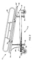
- Fig. 2 illustrates a side elevation of the stretcher device 10, disposed in a Trendelenberg position.
- FIG. 2 which shows bottom frame assembly 14 connected by hydraulic cylinders 16 to top support assembly 12, pressure has been generated in the hydraulic systems by means of pump lever 18.
- hydraulic controls 21, connected to hydraulic valving by means control cable 22 have been set to provide pressurized hydraulic fluid to only one pair of hydraulic cylinders 16, in the Figure, the cylinders adjacent to hydraulic system housing 20, on each side of the stretcher.
- the top support assembly 12 of stretcher 10 is disposed at an angle relative to the horizontal, termed a "Trendelenberg" position.
- the Figure shows restraining rails 28 in their raised, or safety position, secured therein by tapered lock assemblies 32.
- the backrest support yoke 26 has been disengaged from the backrest adjustment notches, so that the backrest is in its lowered, inoperative mode.
- intravenous support pole 30 has been folded down to its storage position, in which it is secured by adjacent tapered lock assembly 32 ⁇ .
- the Figure illustrates a Trendelenberg position in which the foot end of the stretcher 10 has been elevated.
- Hydraulic controls 21 can be set, however, so that hydraulic pressure is furnished only to the pair of hydraulic cylinders 16 located at the head end of the stretcher, in the Figure, the end at which the intravenous support pole 30 is located, resulting in the head of the patient being elevated, while the patient's feet are lowered.
- the hydraulic controls 21 are set so that hydraulic pressure is furnished to each pair of hydraulic cylinders 16, i.e., at both the head and foot of the stretcher, the stretcher can be elevated in a horizontal position.
- Fig. 3 shows an isometric view of the framework of a stretcher 10, simplified for purposes of illustration, and detailing some its hydraulic and mechanical linkages.
- the Figure shows one pair of hydraulic cylinders 16 attached to the top support assembly by means of piston rods 17, attached at pivot points 41, while another pair of hydraulic cylinders is attached by piston rods in piston rod slots 39.
- top support assembly 12 is adjusted in the Trendelenberg position, the piston rods 17 attached to piston rod slots 39 are free to move in the slots, thus accommodating the required change in length of that part of the top support assembly positioned between the pairs of hydraulic cylinders 16, said change in length being necessary to accomodate the angle of the top support assembly imposed by its positioning in the Trendelenberg configuration.
- piston rod slot 39 is shown disposed at the right end of the stretcher, while piston rod pivot point 41 is located at the other end, adjacent to the hydraulic system housing.
- the hydraulic fluid lines 49 show the interconnection between pairs of hydraulic cylinders 16, and exemplify how hydraulic fluid may be diverted to each pair of cylinders separately, from the hydraulic pump located in hydraulic system housing 20, thus allowing hydraulic fluid to be directed to the two pairs of cylinders, separately.
- each pair of cylinders While the interconnection of each pair of cylinders allows the end of the stretcher supported by the pair of cylinders to be raised or lowered by the cylinders operating simultaneously, it is necessary to connect the piston rods 17 of each pair with a stabilizer bar 33.
- the stabilizer bar 33 which is permanently attached to piston rods 17 which it connects, is necessary to prevent lateral tilting of the top support assembly 12 in those instances in which an unbalanced force is applied to one side of the table.
- Fig. 4 is a front elevation of a tapered lock assembly, generally 32, illustrating the mechanism employed to secure side rails 28 and intravenous support pole 30 in a selected position.
- a bolt housing 40 is shown supported by members forming part of top support assembly 12. Contained in bolt housing 40 are locking bolt 34, which is urged by spring 38 into a locking hole 42 in the receiver 44 fixed to restraining rail 28.
- the lock assembly 32 is operated by applying a manual force to bolt handle 36, which is attached to locking bolt 34, in a direction which opposes the force exerted by spring 38. This causes bolt 34 to slide downward in passageway 37, disengaging the conical top of the locking bolt from a locking hole 42.
- the restraining rail 28 can thereupon be rotated to its desired position, a position in which a locking hole 42 is in alignment with locking bolt 34.
- spring 38 will urge locking bolt 34 into the aligned locking hole 42, thus firmly securing and locking the restraining rail in position, due to the action of the spring.
- the tapered lock assembly 32 is not only easy to operate, but the conical, or tapered end of locking bolt 34 is rugged, long-wearing, and tends to be self-aligning. While three locking holes 42 are shown in the Figure, more or fewer such holes may be provided, depending upon the positions in which it is desired to secure the feature to be locked.
- Fig. 5 illustrates a right side elevation of the spring-loaded tapered lock assembly 32 of Fig. 4. Included in bolt housing 40 may be seen clarifying details of locking bolt 34, bolt handle 36, and spring 38. Also shown is adjustment slot 35 down which bolt handle 36 is forced, when adjusting restraining rail 28. The Figure shows the fastening of receiver 44 to restraining rail 28, by means of a key 43. The positioning of bolt housing 40 adjacent members of top support assembly 12 is also shown.
- Fig. 6 is a partial cross-section of an X-ray top which may be employed in fabricating stretcher top 23.
- the Figure shows a lamination comprising an inner core 46 sandwiched between two outer surface skins 48 in a "box" configuration, the surface skins being overlapped on the side edges.
- the patient In the course of conducting X-ray examinations of patients, the patient is normally supported on a table between a source of X-radiation, and the film on which an X-ray picture will be received.
- the material from which the table is made must possess several characteristics. First of all, it must be strong enough to support the patient, and at the same time it must be permeable to X-rays, or X-ray blockage will result in so much data loss that it will be impossible to produce a meaningful image on the film.
- the material must also exhibit minimal "scatter", or diffraction of X-rays passing through it, to obtain good resolution, and a sharp image.
- the term "data" loss is defined as the amount of gamma rays produced by a radioactive isotope source which are diffracted from a straight line path by a material interposed between the source and a detector, such as a scintillation camera detector.
- materials containing carbon graphite mats have been employed because of their excellent X-ray permeability characteristics, rigidity, and high strength. Such, mats are produced from carbon graphite filamentary material, particularly fibers woven into fabric, surrounded by an encapsulating plastic resin so to form a substantially rigid sheet.
- the combination of a box-type, laminate structure, in combination with two outer surface skins, only one of which is of the carbon graphite type, the other being of fiberglass, a material previously believed to be unacceptable for X-ray purposes provides a high strength, relatively low cost laminate, ideally suited for an X-ray diagnostic patient support surface.
- a surface is ideally suited for use in stretcher devices for reasons including its rigidity, high strength, lightweight, and relatively low cost.
- one outer surface skin 48 will be made from a mat of carbon graphite filamentary material encapsulated in a plastic resin, typically the mat itself comprising about 1/3 of the weight of the surface skin, the balance being other components, including particularly the encapsulating plastic resin.
- the other surface skin 48 is comprised of fiberglass containing from about 20% to 35% by weight of fiberglass filamentary material, for example, chopped strand fiberglass, the balance being resin, such as for example, Koppers 6604-T resin.
- the outer surface skins include a layer of gel coat for cosmetic reasons.
- the fiberglass surface skin thickness be in the range of about 0.01 to 0.12 inches if an undesirable level of data loss and scatter is to be avoided, and a skin thickness of about 0.01 to 0.08 provides particularly good X-ray results.
- the carbon graphite surface skin layer is more transparent to the passage of X-rays, the surface skin 28 made from it will have a similar thickness for a number of reasons including cost, structural considerations, and the like.
- Inner core 46 may be made from a variety of materials, however, the use of closed-cell rigid foams is especially useful.
- foams with cells having a diameter greater than about 8 to 10 mils have been found to be particularly advantageous, with the polymethylacrylimide foam being especially preferred for a variety of reasons including particularly, its lightweight and great strength.
- inner cores made from foams of the type described provide a number of advantages, including ease of fabrication, balsawood cores may also be employed.
- Inner core 46 will usually have a thickness of from about 0.18 to 2 inches, however, in a preferred embodiment, an inner core of from about 0.12 to 2.00 inches thick is used.
- the components of the lamination i.e., the outer surface skins 48 and inner core 46 are laid up in any of the ways well known in the art, and can be secured together by the adhesion obtained from a coating of resin, for example, the resin used to form the fiberglass or carbon graphite surface skins.
- Laminations of the type described have been found to be capable of passing up to about 94% of the X-rays directed through them, while producing negligible scatter, well below the 14% level previously referred to.
- either of the outer surface skins 48 may be in contact with the patient, that is, constitute the upper horizontal surface skin, ordinarily, the upper surface skin will be that containing the carbon graphite mat.
- a surface skin comprising a matrix of fibers, preferably in the form of a woven mat, formed from high molecular weight polyethylene, generally from about 1 to 5 million, and possessing a very high degree of crystalline orientation, for example, from about 95% to 99%, encapsulated in a plastic resin, for instance a polyester resin, may be substituted for the fiberglass skin, or for both it and the carbon graphite skin.
- a plastic resin for instance a polyester resin
- Such fibers produced by a process called “gel-spinning” in which the polyethylene polymer is dissolved for the purpose of disentangling the polymer chains, and then spun, include those produced by the Allied Signal Company of Orlando, Virginia, marketed under the Trademark "SPECTRA" fibers.
- the thickness of the resin encapsulated polyethylene fiber surface skins substituted for the fiberglass surface skins previously referred to, or for both those and the carbon graphite surface skins, will normally have a thickness within the same range described in connection with the substituted, surface skins.
- the encapsulated polyethylene fiber surface skins make possible construction of box-type laminated structures of the type described, which have great physical strength, as well as the ability to pass up to about 96% to 97% of the X-rays directed through such structures, and with only negligible scatter.
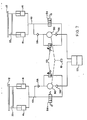
- Fig. 7 is a schematic diagram of the hydraulic system of the stretcher device.
- Fig. 7 shows top support assembly 12 attached to the piston rods of hydraulic cylinders 16, the piston rods of each pair of hydraulic cylinders being connected by stabilizer bars 33.
- the hydraulic cylinders 16 are connected by the hydraulic lines 49 to hydraulic pumps 50, which are operated by pump lever 18.
- Pump lever 18 is normally actuated by the foot of the user, although a hand operated lever could also be employed. If desired, separate activating pump levers 18 could be supplied for each of the pumps 40, or the pumps could be activated electrically, for example, with electricity supplied by a battery.
- Also shown are the hydraulic fluid reservoir 53, check valves 56 and 58, 2-way valves 54, and pressure relief valves 52.
- Operation of the system begins by activating the pumps 50 with pump lever 18. This draws hydraulic fluid from hydraulic fluid reservoir 53 past check valves 56 which allow the fluid to pass through them to the pumps, but prevent flow in the reverse direction.
- the pump forces the hydraulic fluid through check valves 58, the latter preventing reverse flow, and on to hydraulic cylinders 16 causing the piston rods, and therefore the top support assembly 12 of the stretcher device to rise.
- the operation described is that which occurs when two-way valves 54 are positioned in their closed, fluid blocking mode, illustrated. When the two-way valves are positioned in their open mode, hydraulic fluid is allowed to escape from hydraulic cylinders 16 and return through the two-way valves in the direction of the arrows to the hydraulic fluid reservoir 53, resulting in a lowering of the piston rods.
- one of the two-way valves 54 open, while the other remains closed, a setting which results in only one end of the stretcher device rising, positioning the stretcher device in the Trendelenberg configuration.
- a two-way valve 54 may be opened, releasing hydraulic therefrom, until the top support assembly 12 of the stretcher device drops to a desired lower position, at which point the two-way valve is again closed, maintaining the top support of the stretcher in the desired position.
- Pressure relief valves 52 are adjusted to open at a pressure just below that at which hydraulic system component damage would occur. When such pressure is reached, the pressure relief valve 52 opens, causing hydraulic fluid to recycle from the pumps 50 back to the hydraulic fluid reservoir 53.
- Fig. 8 is a cross section of a hydraulic cylinder 16 employed with the stretcher device of the invention, illustrating the "free-floating" relationship between the piston rod 17 and the hydraulic cylinder 16.
- the piston rod 17 is fastened to the piston by means of a wrist pin 66, anchored in the walls of the piston, which passes through a wrist pin bore hole 64 in the piston rod 17.
- the diameter of wrist pin 66 is sufficiently smaller than the wrist pin bore hole 64 through which it extends to allow the piston rod a relatively high degree of freedom to move or "float" about the wrist pin. This freedom allows the piston rod to accommodate itself to the slight misalignments which result from applied loads, manufacturing tolerances, or otherwise, avoiding binding between the piston and the cylinder wall of the type which would render the cylinder inoperable.
- the required difference in diameter between the wrist pin and the wrist pin bore hole will depend upon the relative dimensions of the piston rod and piston; however, in the case of a piston about 1 inch in diameter, fixed to a piston rod having a diameter of about 3/4 inch, the difference in the diameter of the wrist pin and the wrist pin bore hole will commonly be about 1/16 inch. In other words, in the case of a wrist pin approximately 1/8 inch in diameter, a typical size, the wrist pin bore hole will have a diameter of about 3/16 inch.
Landscapes
- Health & Medical Sciences (AREA)
- Life Sciences & Earth Sciences (AREA)
- Animal Behavior & Ethology (AREA)
- General Health & Medical Sciences (AREA)
- Public Health (AREA)
- Veterinary Medicine (AREA)
- Nursing (AREA)
- Medical Informatics (AREA)
- Engineering & Computer Science (AREA)
- High Energy & Nuclear Physics (AREA)
- Biomedical Technology (AREA)
- Physics & Mathematics (AREA)
- Nuclear Medicine, Radiotherapy & Molecular Imaging (AREA)
- Optics & Photonics (AREA)
- Pathology (AREA)
- Radiology & Medical Imaging (AREA)
- Biophysics (AREA)
- Heart & Thoracic Surgery (AREA)
- Molecular Biology (AREA)
- Surgery (AREA)
- Rehabilitation Therapy (AREA)
- Accommodation For Nursing Or Treatment Tables (AREA)
- Materials For Medical Uses (AREA)
Applications Claiming Priority (4)
| Application Number | Priority Date | Filing Date | Title |
|---|---|---|---|
| US3165287A | 1987-03-30 | 1987-03-30 | |
| US31652 | 1987-03-30 | ||
| US07/132,927 US4912787A (en) | 1987-03-30 | 1987-12-15 | Hydraulic stretcher device |
| US132927 | 1998-08-12 |
Related Child Applications (2)
| Application Number | Title | Priority Date | Filing Date |
|---|---|---|---|
| EP91103778.6 Division-Into | 1988-03-17 | ||
| EP19910103778 Division EP0433272A3 (de) | 1987-03-30 | 1988-03-17 | Tragevorrichtung für Patienten |
Publications (3)
| Publication Number | Publication Date |
|---|---|
| EP0285290A2 true EP0285290A2 (de) | 1988-10-05 |
| EP0285290A3 EP0285290A3 (en) | 1989-01-18 |
| EP0285290B1 EP0285290B1 (de) | 1992-02-19 |
Family
ID=26707482
Family Applications (2)
| Application Number | Title | Priority Date | Filing Date |
|---|---|---|---|
| EP88302346A Expired - Lifetime EP0285290B1 (de) | 1987-03-30 | 1988-03-17 | Hydraulische Hebevorrichtung für Tragbahren |
| EP19910103778 Withdrawn EP0433272A3 (de) | 1987-03-30 | 1988-03-17 | Tragevorrichtung für Patienten |
Family Applications After (1)
| Application Number | Title | Priority Date | Filing Date |
|---|---|---|---|
| EP19910103778 Withdrawn EP0433272A3 (de) | 1987-03-30 | 1988-03-17 | Tragevorrichtung für Patienten |
Country Status (4)
| Country | Link |
|---|---|
| US (1) | US4912787A (de) |
| EP (2) | EP0285290B1 (de) |
| CA (1) | CA1294576C (de) |
| DE (1) | DE3868423D1 (de) |
Cited By (2)
| Publication number | Priority date | Publication date | Assignee | Title |
|---|---|---|---|---|
| DE3902396A1 (de) * | 1988-02-24 | 1989-09-07 | Helmut Koetter | Krankenbett |
| DE3902334A1 (de) * | 1989-01-27 | 1990-08-09 | Eckhart Dewert | Bett mit einem zumindest in der neigung verstellbaren liegeelement |
Families Citing this family (68)
| Publication number | Priority date | Publication date | Assignee | Title |
|---|---|---|---|---|
| US5054140A (en) * | 1989-03-08 | 1991-10-08 | Bingham Grady A | Hospital bed device |
| US5063624A (en) * | 1990-05-08 | 1991-11-12 | Stryker Corporation | Manual/electric twin jack bed |
| US5131103A (en) * | 1990-12-18 | 1992-07-21 | Thomas Jimmy W | Integrated back support and bed apparatus and method |
| US5520091A (en) * | 1993-03-01 | 1996-05-28 | American Sterilizer Company | Hydraulically coupled position locking device for surgical tables |
| DE4309169C2 (de) * | 1993-03-23 | 1995-07-06 | Rene Schmitz | Rollentrage für den Krankentransport in Krankenhäusern |
| US5715548A (en) * | 1994-01-25 | 1998-02-10 | Hill-Rom, Inc. | Chair bed |
| GB9404181D0 (en) * | 1994-03-04 | 1994-04-20 | Smiths Industries Plc | Trolleys |
| US5490297A (en) * | 1994-09-01 | 1996-02-13 | Beta Medical Products, Inc. | Mobile imaging table |
| US6212714B1 (en) * | 1995-01-03 | 2001-04-10 | Hill-Rom, Inc. | Hospital bed and mattress having a retracting foot section |
| US6584628B1 (en) * | 1995-08-04 | 2003-07-01 | Hill-Rom Services, Inc. | Hospital bed having a rotational therapy device |
| US5732423A (en) | 1995-08-04 | 1998-03-31 | Hill-Rom, Inc. | Bed side rails |
| US5771513A (en) * | 1996-06-03 | 1998-06-30 | Beta Medical Products, Inc. | X-ray compatible, partially flexible patient support |
| US6000076A (en) * | 1996-10-23 | 1999-12-14 | Hill-Rom, Inc. | Procedural stretcher recline controls |
| US5860176A (en) * | 1997-09-24 | 1999-01-19 | Norberg; William J. | Pediatric critical care transport system |
| US6352240B1 (en) * | 1999-05-13 | 2002-03-05 | Hill-Rom Services, Inc. | Hydraulic control apparatus for a hospital bed |
| US6792633B1 (en) * | 1999-10-12 | 2004-09-21 | Takano Co., Ltd. | Stretcher |
| EP1754462B1 (de) * | 1999-12-29 | 2016-07-13 | Hill-Rom Services, Inc. | Patientenliege mit Aktuatorbetätigungsglied |
| DE10001687A1 (de) * | 2000-01-11 | 2001-07-12 | Albrecht Hoerlin | Krankenbett |
| WO2001074645A1 (en) * | 2000-04-03 | 2001-10-11 | Trw Inc. | Electric steering apparatus |
| US6779209B2 (en) * | 2000-12-29 | 2004-08-24 | Hill-Rom Services, Inc. | Bed siderail apparatus |
| JP2005500083A (ja) | 2001-01-25 | 2005-01-06 | ヒル−ロム サービシーズ,インコーポレイティド | 外科用テーブルのための油圧式アクチュエータ装置 |
| USD463179S1 (en) | 2001-04-05 | 2002-09-24 | Hill-Rom Services, Inc. | Top rail member of a bed siderail |
| USD458481S1 (en) | 2001-04-05 | 2002-06-11 | Hill-Rom Services, Inc. | Slats of a bed siderail |
| USD459119S1 (en) | 2001-04-05 | 2002-06-25 | Hill-Rom Services, Inc. | Siderail support arm |
| US6694549B2 (en) | 2001-04-20 | 2004-02-24 | Hill-Rom Services, Inc. | Bed frame with reduced-shear pivot |
| WO2003053322A2 (en) * | 2001-12-20 | 2003-07-03 | Hill-Rom Services, Inc. | Bed siderails |
| US6976696B2 (en) * | 2002-08-30 | 2005-12-20 | Neomedtek | Transportable medical apparatus |
| JP4712385B2 (ja) | 2002-09-06 | 2011-06-29 | ヒル−ロム サービシーズ,インコーポレイティド | 病院ベッド |
| USD479070S1 (en) | 2002-09-06 | 2003-09-02 | Hill-Rom Services, Inc. | Bed siderail |
| US7073220B2 (en) | 2002-09-06 | 2006-07-11 | Hill-Rom Services, Inc. | Bed siderail having a latch |
| US6898811B2 (en) | 2002-09-10 | 2005-05-31 | Pediatric Medical Devices, Inc. | Device for emergency transport of pediatric patients |
| US7173265B2 (en) | 2003-08-12 | 2007-02-06 | Loma Linda University Medical Center | Modular patient support system |
| CA2542754A1 (en) * | 2003-10-16 | 2005-04-28 | Calypso Medical Technologies, Inc. | Patient support systems for use with radiation therapy systems and other applications |
| US7073219B2 (en) | 2004-01-06 | 2006-07-11 | Teknion Concept | Side rail, hospital bed including the same, method of operating associated thereto and kit for assembling the side rail |
| US7521891B2 (en) * | 2004-06-14 | 2009-04-21 | Fernon-Washington, Inc. | Charging system for recharging a battery of powered lift ambulance cot with an electrical system of an emergency vehicle |
| BRPI0512067B8 (pt) * | 2004-06-14 | 2021-06-22 | Ferno Washington | maca de ambulância com elevador acionado hidraulicamente |
| US7073508B2 (en) * | 2004-06-25 | 2006-07-11 | Loma Linda University Medical Center | Method and device for registration and immobilization |
| US7398571B2 (en) | 2004-09-24 | 2008-07-15 | Stryker Corporation | Ambulance cot and hydraulic elevating mechanism therefor |
| JP5055523B2 (ja) * | 2004-09-24 | 2012-10-24 | ストライカー コーポレイション | 救急車用簡易ベッド及びそのための油圧式昇降機構 |
| US7913337B1 (en) * | 2005-05-31 | 2011-03-29 | Masson Marcos V | Ambulatory surgical gurney |
| DE102006037145A1 (de) * | 2006-08-09 | 2008-02-14 | OKIN Gesellschaft für Antriebstechnik mbH | Bett |
| EP2095374A4 (de) | 2006-11-21 | 2012-05-30 | Univ Loma Linda Med | Vorrichtung und verfahren zur fixierung von patienten zur bruststrahlungstherapie |
| US8239986B2 (en) * | 2008-03-13 | 2012-08-14 | Hill-Rom Services, Inc. | Siderail assembly for a patient-support apparatus |
| DE102009051048A1 (de) * | 2009-10-27 | 2011-04-28 | Schmuhl Faserverbundtechnik Gmbh & Co. Kg | Patientenliege |
| WO2014168532A1 (en) * | 2012-04-13 | 2014-10-16 | Stille Ab | Improved surgical tables |
| USD710507S1 (en) | 2013-09-23 | 2014-08-05 | Hill-Rom Services Pte. Ltd. | Patient bed |
| USD710509S1 (en) | 2013-09-23 | 2014-08-05 | Hill-Rom Services Pte. Ltd. | Head rail for a patient bed |
| USD710510S1 (en) | 2013-09-23 | 2014-08-05 | Hill-Rom Services Pte. Ltd. | Foot rail for a patient bed |
| EP2873400B1 (de) | 2013-11-18 | 2018-01-31 | Völker GmbH | Personentragevorrichtung |
| DK178326B1 (da) * | 2013-12-20 | 2015-12-14 | Turnaid Aps | Personvendesystem |
| CN103919651A (zh) * | 2014-04-10 | 2014-07-16 | 哈尔滨飞机工业集团有限责任公司 | 一种机载救援担架 |
| DE102014109377B4 (de) | 2014-07-04 | 2017-11-16 | MAQUET GmbH | Vorrichtung zur Höhenverstellung eines Operationstischs und Operationstisch mit einer derartigen Vorrichtung |
| DE102014109376B4 (de) | 2014-07-04 | 2017-11-09 | MAQUET GmbH | Operationstischfuß für einen Operationstisch |
| DE102014109375A1 (de) * | 2014-07-04 | 2016-01-07 | MAQUET GmbH | Operationstischsäule für einen Operationstisch |
| BR102014017147A2 (pt) * | 2014-07-11 | 2016-01-12 | Cláudia De Oliveira | maca meia-lua multifuncional |
| USD770824S1 (en) | 2014-08-12 | 2016-11-08 | Hill-Rom Services, Inc. | Barrier for a hospital bed |
| USD769042S1 (en) | 2014-08-12 | 2016-10-18 | Hill-Rom Services, Inc. | Head end siderail |
| USD768422S1 (en) | 2014-08-12 | 2016-10-11 | Hill-Rom Services, Inc. | Foot end siderail |
| USD771259S1 (en) | 2015-01-29 | 2016-11-08 | Hill-Rom Services, Inc. | Foot rail for patient bed |
| USD770829S1 (en) | 2015-01-29 | 2016-11-08 | Hill-Rom Services, Inc. | Head rail for patient bed |
| USD804882S1 (en) | 2016-05-28 | 2017-12-12 | Hill-Rom Services, Inc. | Headrail |
| USD804883S1 (en) | 2016-05-28 | 2017-12-12 | Hill-Rom Services, Inc. | Footrail |
| EP3412243A1 (de) * | 2017-06-08 | 2018-12-12 | Servicio Andaluz De Salud | Starre pvc-schaumstoffbahnen zur verwendung in der radiotherapie und/oder diagnosebildgebung |
| US11019942B1 (en) | 2018-05-21 | 2021-06-01 | Pediatric Medical Llc | Cushions for safe, sanitary transportation of children |
| US12186253B2 (en) * | 2021-01-19 | 2025-01-07 | University Of Utah Research Foundation | Trauma gurney with enhanced patient transfer capabilities |
| BR112023015605A2 (pt) * | 2021-02-05 | 2023-10-31 | De Oliveira Claudia | Mesa obstétrica multifuncional |
| JP7664118B2 (ja) * | 2021-08-11 | 2025-04-17 | キヤノンメディカルシステムズ株式会社 | 寝台装置及び医用画像診断装置 |
| GB2635674A (en) * | 2023-11-18 | 2025-05-28 | Kbx Tech Ltd | Foldable treatment table |
Family Cites Families (21)
| Publication number | Priority date | Publication date | Assignee | Title |
|---|---|---|---|---|
| US1704979A (en) * | 1929-03-12 | Frank ktjsterle and charles h | ||
| US2014244A (en) * | 1935-04-16 | 1935-09-10 | Bramlett Frank | Patient handler |
| US2387940A (en) * | 1944-08-21 | 1945-10-30 | Herbert E Page | Hydraulic jack |
| US2621574A (en) * | 1945-10-26 | 1952-12-16 | Thomas Georges Alfred | Rocking axle tractor with hydraulic lift |
| US3253284A (en) * | 1965-02-08 | 1966-05-31 | Gendron Wheel Company | Adjustable stretcher |
| GB1077596A (en) * | 1965-04-12 | 1967-08-02 | H E Adamsson Ab | Hospital bed |
| US3393004A (en) * | 1966-10-06 | 1968-07-16 | Simmons Co | Hydraulic lift system for wheel stretchers |
| BE757071A (nl) * | 1969-10-07 | 1971-03-16 | Stiegelmeyer & Co Gmbh | Ziekenbed |
| AT318798B (de) * | 1970-10-07 | 1974-11-11 | Stiegelmeyer & Co Gmbh | Krankenbett |
| US3813712A (en) * | 1972-06-28 | 1974-06-04 | N Bonnin | Patient stretcher transport system |
| US3820838A (en) * | 1972-10-06 | 1974-06-28 | Gendron Diemer Inc | Hydraulic system for wheeled stretchers |
| US3947686A (en) * | 1974-04-25 | 1976-03-30 | The Babcock & Wilcox Co. | Graphite composite X-ray transparent patient support |
| JPS5524893B2 (de) * | 1975-02-08 | 1980-07-02 | ||
| DE2658627A1 (de) * | 1976-12-23 | 1978-06-29 | Steinbock Gmbh | Vorrichtung zum heben, senken und/oder transportieren liegender personen |
| US4145612A (en) * | 1977-08-31 | 1979-03-20 | The Babcock & Wilcox Company | X-ray patient support stretcher and method for fabrication |
| US4175783A (en) * | 1978-02-06 | 1979-11-27 | Pioth Michael J | Stretcher |
| US4186456A (en) * | 1978-07-14 | 1980-02-05 | American Hospital Supply Corporation | Rail system for bed or stretcher |
| JPS55143817U (de) * | 1979-04-02 | 1980-10-15 | ||
| US4299209A (en) * | 1979-04-27 | 1981-11-10 | Behrens James D | Vertebral immobilization and extrication support |
| DE3233363A1 (de) * | 1982-09-08 | 1984-03-08 | Stierlen-Maquet Ag, 7550 Rastatt | Tisch zur lagerung von patienten |
| US4566445A (en) * | 1983-07-29 | 1986-01-28 | Jelsma Richard K | Stretcher for persons with spinal injuries |
-
1987
- 1987-12-15 US US07/132,927 patent/US4912787A/en not_active Expired - Fee Related
-
1988
- 1988-03-17 EP EP88302346A patent/EP0285290B1/de not_active Expired - Lifetime
- 1988-03-17 DE DE8888302346T patent/DE3868423D1/de not_active Expired - Lifetime
- 1988-03-17 EP EP19910103778 patent/EP0433272A3/de not_active Withdrawn
- 1988-03-29 CA CA000562844A patent/CA1294576C/en not_active Expired - Lifetime
Cited By (2)
| Publication number | Priority date | Publication date | Assignee | Title |
|---|---|---|---|---|
| DE3902396A1 (de) * | 1988-02-24 | 1989-09-07 | Helmut Koetter | Krankenbett |
| DE3902334A1 (de) * | 1989-01-27 | 1990-08-09 | Eckhart Dewert | Bett mit einem zumindest in der neigung verstellbaren liegeelement |
Also Published As
| Publication number | Publication date |
|---|---|
| DE3868423D1 (de) | 1992-03-26 |
| US4912787A (en) | 1990-04-03 |
| EP0433272A3 (de) | 1991-07-24 |
| CA1294576C (en) | 1992-01-21 |
| EP0433272A2 (de) | 1991-06-19 |
| EP0285290B1 (de) | 1992-02-19 |
| EP0285290A3 (en) | 1989-01-18 |
Similar Documents
| Publication | Publication Date | Title |
|---|---|---|
| US4912787A (en) | Hydraulic stretcher device | |
| US7111340B2 (en) | Bariatric gurney and process | |
| US4691393A (en) | Angular tilt control mechanism for a wheeled stretcher | |
| US7131769B2 (en) | Stretcher with dedicated multi-functional removable floating patient support platform | |
| US5135350A (en) | Method for transporting a patient from an ambulance | |
| US5263213A (en) | Patient support surface that includes foldable segments made of composite material | |
| US6266831B1 (en) | Storable trauma board support | |
| US6546577B1 (en) | Mobile medical emergency and surgical table | |
| JP4806152B2 (ja) | イメージングストレッチャ | |
| US5771513A (en) | X-ray compatible, partially flexible patient support | |
| US6886194B2 (en) | Patient transport system | |
| US11103403B2 (en) | Lifting system with lifting device and cantilevered support platform | |
| EP2241301A2 (de) | Ausrüstungsträgerschiene für Krankenbett | |
| US8052326B2 (en) | Linear bearing | |
| US5068935A (en) | Flotation therapy bed having two part construction | |
| US4649581A (en) | Patient lift assembly | |
| US3631242A (en) | Fluoroscope top for cardiac bed which is swingable about a vertical axis of the bed | |
| US20070056106A1 (en) | Emergency management triage bed | |
| CH470177A (de) | Fahrbares Hebegerät, insbesondere für den Krankentransport | |
| CN218572447U (zh) | 一种转运轮椅 | |
| AU2005316156B2 (en) | Stretcher with dedicated multi-functional removable floating patient support platform | |
| DE8904279U1 (de) | Krankentragenuntergestell mit einem Geräteraum für medizinische Geräte und Instrumente, insbesondere für den klinischen Bereich | |
| CA3036105C (en) | Lifting system with lifting device and cantilevered support platform | |
| WO2021148864A1 (en) | Smooth lateral patient transfer apparatus | |
| DE8803137U1 (de) | Bettseitenteil |
Legal Events
| Date | Code | Title | Description |
|---|---|---|---|
| PUAI | Public reference made under article 153(3) epc to a published international application that has entered the european phase |
Free format text: ORIGINAL CODE: 0009012 |
|
| AK | Designated contracting states |
Kind code of ref document: A2 Designated state(s): DE FR GB SE |
|
| PUAL | Search report despatched |
Free format text: ORIGINAL CODE: 0009013 |
|
| AK | Designated contracting states |
Kind code of ref document: A3 Designated state(s): DE FR GB SE |
|
| 17P | Request for examination filed |
Effective date: 19890626 |
|
| 17Q | First examination report despatched |
Effective date: 19901109 |
|
| GRAA | (expected) grant |
Free format text: ORIGINAL CODE: 0009210 |
|
| AK | Designated contracting states |
Kind code of ref document: B1 Designated state(s): DE FR GB SE |
|
| PG25 | Lapsed in a contracting state [announced via postgrant information from national office to epo] |
Ref country code: SE Effective date: 19920219 Ref country code: FR Effective date: 19920219 |
|
| XX | Miscellaneous (additional remarks) |
Free format text: TEILANMELDUNG 91103778.6 EINGEREICHT AM 17/03/88. |
|
| REF | Corresponds to: |
Ref document number: 3868423 Country of ref document: DE Date of ref document: 19920326 |
|
| EN | Fr: translation not filed | ||
| PLBE | No opposition filed within time limit |
Free format text: ORIGINAL CODE: 0009261 |
|
| STAA | Information on the status of an ep patent application or granted ep patent |
Free format text: STATUS: NO OPPOSITION FILED WITHIN TIME LIMIT |
|
| 26N | No opposition filed | ||
| PGFP | Annual fee paid to national office [announced via postgrant information from national office to epo] |
Ref country code: GB Payment date: 19960314 Year of fee payment: 9 |
|
| PGFP | Annual fee paid to national office [announced via postgrant information from national office to epo] |
Ref country code: DE Payment date: 19960530 Year of fee payment: 9 |
|
| PG25 | Lapsed in a contracting state [announced via postgrant information from national office to epo] |
Ref country code: GB Effective date: 19970317 |
|
| GBPC | Gb: european patent ceased through non-payment of renewal fee |
Effective date: 19970317 |
|
| PG25 | Lapsed in a contracting state [announced via postgrant information from national office to epo] |
Ref country code: DE Effective date: 19971202 |